1. Introduction
In the past few years, growing interest has been shown in continuum robotics. Compared to conventional rigid-link robots, continuum robots can adapt to their surroundings thanks to their “infinite” number of degrees of freedom (DOFs), making them a great asset in surgery [Reference Dupont, Simaan, Choset and Rucker1, Reference Burgner-Kahrs, Rucker and Choset2], search and rescue [Reference Yamauchi, Ambe, Nagano, Konyo, Bando, Ito, Arnold, Yamazaki, Itoyama, Okatani, Okuno and Tadokoro3, Reference Der Maur, Djambazi, Haberthür, Hörmann, Kübler, Lustenberger, Sigrist, Vigen, Förster, Achermann, Hampp, Katzschmann and Siegwart4], various industries such as aeronautics [Reference Mohammad, Russo, Fang, Dong, Axinte and Kell5, Reference Dong, Wang, Mohammad, Ba, Russo, Norton, Kell and Axinte6] and agriculture [Reference Yeshmukhametov, Koganezawa, Yamamoto, Buribayev, Mukhtar and Amirgaliyev7], and soft grippers [Reference Shintake, Cacucciolo, Floreano and Shea8, Reference Homberg, Katzschmann, Dogar and Rus9]. Various categories of continuum robots exist [Reference Russo, Sadati, Dong, Mohammad, Walker, Bergeles, Xu and Axinte10]. Among them, the most well-known are the following ones: concentric tube robots [Reference Mitros, Sadati, Henry, Da Cruz and Bergeles11, Reference Alfalahi, Renda and Stefanini12], which consist of multiple pre-curved tubes that can retract into a main tube; tendon-driven robots, which actuate the devices through cables attached at different levels of the manipulator on one end and to actuators at the other extremities [Reference Li, Kang, Geng and Guglielmino13, Reference Pachouri and Pathak14]; and fluidic continuum robots [Reference Greer, Morimoto, Okamura and Hawkes15, Reference Giannaccini, Xiang, Atyabi, Theodoridis, Nefti-Meziani and Davis16], which employ antagonistic inflatable chambers or pneumatic muscles to change shape. Tendon-driven manipulators can be designed in many ways, from discrete joint robots [Reference Kim, Woo and Suh17] to helical spring manipulators [Reference Guan, Stella, Santina, Leng and Hughes18], among others. Further, new types of continuum robots continue to emerge, such as vine-inspired eversive robots [Reference Blumenschein, Coad, Haggerty, Okamura and Hawkes19, Reference Ataka, Abrar, Putzu, Godaba and Althoefer20].
To create a continuum device, the user needs to consider the choice of actuation, as well as the complexity of modeling, the ease of assembly, and the cost. It is not uncommon for pneumatic continuum robots to be monolithic (e.g., pneunets), but their manufacturing remains complex [Reference Song, Wang, Liu, Song and Zhang21, Reference Yoon and Yun22]. Conversely, rod-driven and tendon-driven continuum robots (TDCR) are commonly composed of numerous elements, which can require long and meticulous hours of work to assemble (e.g., the robot in [Reference Troncoso, Robles-Linares, Russo, Elbanna, Wild, Dong, Mohammad, Kell, Norton and Axinte23] has hundreds of miniaturized components that require a careful manual assembly). Additionally, the manufacturing process of multiple elements can increase the cost of the robot, particularly when high-precision machining is required. The high cost and complex assembly of these robots significantly limit their accessibility, affecting their transfer to industry and the possibility of deploying these robots in specific environments (i.e., radioactive environments would require disposable systems). Furthermore, these factors lead to customized robots being developed for specific tasks [Reference Grassmann, Lilge, Le and Burgner-Kahrs24], further limiting the standardization and benchmark development for this class of robots.
This lack of open-source models, software, and resources is actively hindering the development of continuum robots, which are often developed at a research laboratory up to the Technological Readiness Level 6 and then miss going further, hindered by the lack of resources and regulations [Reference Russo, Sadati, Dong, Mohammad, Walker, Bergeles, Xu and Axinte10]. To encourage the development and adoption of continuum robots up to commercial readiness, the accessibility of continuum robotic research must improve, especially from a design perspective. One option to democratize continuum robot design is to focus on the general optimization of the designs of continuum manipulators [Reference Zhu, Zhang, Zhang, Liang, Zang, Li and Wang25] to improve their efficiency progressively [Reference Khalil, Habib, Seadby and Maged26]. Another option is the creation and sharing of open-source designs. To this end, some research groups shared their models and data for specific applications: the minimally invasive surgery tendon-actuated device, ENDO, in ref. [Reference Clark, Mathivannan and Rojas27] and the continuum tendon-driven manipulator for underwater remotely operated vehicles in ref. [Reference Sitler and Wang28]. More general open-source design projects exist for fluidic continuum robots, notably the Soft Robotics Toolkit, created as an educational tool that presents both design, sensing, and control aspects [Reference Beaudette, Gerez, Holland, Berdnt and Park29, Reference Holland, Park, Polygerinos, Bennett and Walsh30]. However, to the best of the authors’ knowledge, the only toolkit to specifically address TDCR is the Open Continuum Robotics Project of the Continuum Robotics Laboratory at the University of Toronto [31], which currently provides visualization and simulation tools as well as a generalized actuation module for concentric tube and TDCR, together with an interface to control the actuation module [Reference Grassmann, Shentu, Hamoda, Dewi and Burgner-Kahrs32]. Other open-source software tools for continuum robots exist, such as SoMo [Reference Graule, Teeple, mccarthy, Kim, St. Louis and Wood33].
However, all these open-access tools focus on software and modeling; TDCR designs are usually reported with essential kinematic parameters only, without fully describing the design features or their assembly process, making continuum robot designs hardly reproducible and increasing the barrier to access this research field. For this reason, this paper presents and compares four different continuum robot designs that can be manufactured with easily available materials and technologies. The 3D models of the proposed designs are also included as Supplementary Materials with this paper, providing readers not only with essential kinematic parameters but also with a full knowledge of the entire geometry of the system. This paper expands our previous conference paper [Reference Perugini and Russo34], which analyzes a single monolithic TDCR, with four new designs. These prototypes all allow for an easy assembly, only requiring the threading of the tendons through their routing channel. Additionally, they can all be printed with off-the-shelf TPU and hobby-grade FDM 3D printers, making the manufacturing affordable and accessible. We then tested the manufactured prototypes to characterize their behavior in terms of reachable workspace and precision with the same actuation unit and evaluation criteria as done in ref. [Reference Perugini and Russo34]. The experimental results have been compared to identify the strengths and weaknesses of the proposed designs.
2. Robot design
The four robots presented in this article have been designed with the main goal of having a single print to highly simplify the manufacturing process and the assembly, as it allows us to simply add the tendons through their structure. The four designs are modular, made of a specific backbone unit that is then duplicated along the backbone up to the desired backbone length. For ease of comparison, this paper refers to prototypes with shared length (80.00 mm), external diameter (17.50 mm), and internal diameter (3.50 mm), set to match the design previously presented in ref. [Reference Perugini and Russo34]. However, these dimensions are purely representative, and the system can be scaled according to the capabilities and workspace of the available 3D printers, as well as printing-induced vibrations (which depend on printing speed and on the pressure exerted by the nozzle on the robot backbone while printing), the choice of material and further printing parameters such as infill percentage and pattern, printing temperature, plate temperature, and rafts/brims. Generally, designs from 4 mm up to 200 mm in external diameter can be found in literature, with the minimum size being limited by the minimum wall thickness that the 3D printer can manufacture and the maximum size bound by the 3D printer’s workspace.
The four designs have been obtained by using common geometries for compliant hinges, allowing for robot bending in one or two directions by reducing local stiffness; at the same time, regions with higher stiffness have been preserved to replicate the tendon-routing functionality of continuum robot vertebrae/disks. The four designs presented all achieve local stiffness variation by reducing cross-section area, according to profiles that allow for smoother or harsher changes: a sawtooth profile (V-notch, linear, Fig. 1), a square wave profile (T-notch, high/low, Fig. 2), a circle arc profile (hourglass, sine, Fig. 3), and a helical profile (helix, Fig. 4).
CAD model of the V-notch design: (a) isometric view; (b) front view; (c) side view.

CAD model of the T-notch design: (a) isometric view; (b) front view; (c) side view.

CAD model of the hourglass design: (a) isometric view; (b) front view.

CAD model of the double-helix design: (a) isometric view; (b) front view; (c) side view.

The first design, presented in Fig. 1, is a circular design with a V-shaped notch pattern on the sides. Consequent notches are designed to allow bending on two perpendicular planes, in order to obtain 3D motion. Fillets have been added at the inner extremity of each notch, allowing for more space for the tendon channels. The notches are set at a 45° angle to allow printing without additional support. Similarly to the other designs, the backbone length (80.00 mm) includes cylindrical segments (height of 2.00 mm each) at each extremity of the main body. An additional base (height of 4.00 mm) is used to attach the design to the actuation system, as well as adding stability and guaranteeing base plate adhesion during the print.
The second design, in Fig. 2, presents a T-shaped notch pattern. Similarly to the previous design, consequent notches are rotated by 90° around the backbone axis to allow bending on two perpendicular planes. The notches include fillets on their inner sides to facilitate the printing as well as making the prototype more resistant to fatigue induced by the bending of the robot. Additionally, it allows us to obtain a more precisely comparable result during the displacement finite element analysis (FEA), avoiding stress concentration at the corners of the notches.
The third design created in this article was inspired by the design of a traditional hourglass, as illustrated in Fig. 3. It presents a circular cross-section with varying outer diameter along the backbone, whereas the inner channel diameter remains constant. The thicker sections of this design are used for tendon routing, while the thinner sections facilitate the bending of the robot. Given its axial symmetry, this design can intrinsically achieve 3D motion without requiring alternating designs like the previous two models.
The fourth design, inspired by our DNA’s geometry, is based on a double helix. The two helical bodies present the same pitch and number of revolutions but differ in helix direction, as shown in Fig. 4. The resulting design, while less “discrete” in its development when compared to the V-notch and T-notch design, still results in alternating planes of bending generated by the helices’ intersections alternating along the two main axes of the cross-section.
As mentioned earlier, all four designs present the same main geometric features, with a cylindrical envelope with the same maximum outer diameter and inner channel diameter, as well as tendon-routing channel diameters and locations. These parameters are highlighted in the top view in Fig. 5, shared by all the designs (including [Reference Perugini and Russo34]). Throughout their conception, the secondary parameters of these designs have been tuned through FEA to obtain an equivalent behavior under load. As the aim of this paper is to compare the kinematic behavior of these four designs, the objective of this analysis is only to ensure that the selected geometries do not differ (i.e., same displacement of the control point at the distal end of the backbone), rather than fully simulating motion. For the actual robot characterization, experimental data are favored over FEA here due to the challenge of modeling highly nonlinear behavior such as tendon friction and superelasticity [Reference Raimondi, Russo, Dong and Axinte35]. As such, the design tuning has been set up by matching the displacement of the distal point of the backbone of each design under a set of known loads (up to 2 N) and with fixed base, through FEA, which was run in SolidWorks 2023, using the PBT material profile and with matching mesh parameters, solver, and boundary conditions (fixture on the lower surface of the base plate). As shown by the results in Fig. 6, the mechanical performance of these designs can thus be compared under equivalent conditions.
Top view with characteristic dimensions for the proposed designs.

Results of the finite element analysis of the four new designs as well as the design in ref. [Reference Perugini and Russo34] (on the left), showing an equivalent displacement under load for all the systems.

3. Actuation unit design
The selected actuation unit has been described in ref. [Reference Perugini and Russo34] and is composed of six layers, made out of six disks with a circular shape and a diameter of 75 mm. This allows for affordable and fast manufacturing through 3D printing or laser cutting, with an estimated cost of less than €1.00 per disk and a manufacturing time of less than 10 min (3D printing) or 30 s (laser-cutting). The disks are then separated by commercial electronic board spacers, making the design adaptable in case of changes in the choice of actuators, power supply, or controller (Fig. 7). The first disk at the top of the assembly is used to fix the base of the robot as well as route the antagonistic tendons into the robot segment. Underneath, the second disk routes the tendons out of the linear motors and avoids tangling and similar routing issues. The third and fourth disks are designed to fix the four linear servomotors that actuate the system (Actuonix PQ12). These motors have a 20 mm stroke, with a maximum output of 45 N; alternative linear motors, or rotational motors with pulleys, can also be used with minimal changes to the design of the actuation unit. As a control board, a Polulu Micro Maestro 6-Channel USB Servo Controller has been selected for this work; the microcontroller is fixed to the fifth disk. Alternative solutions include Arduino or Raspberry Pi boards, potentially with a PWM driver to control up to 15 servomotors if the system’s DOFs need to be scaled up. In the reported prototype, the Micro Maestro controller is linked to a computer via a USB cable to transfer the signal from the Maestro Control Center software to the motors. The fifth disk also allows the passage of wires through a 25 mm diameter hole. Finally, the six disk lodges the power supply for the controller and the linear servomotors, which comes in the shape of a 6V battery pack with four AA batteries but can be easily replaced with a rechargeable Li-Io battery or equivalent alternatives with no impact to performance.
CAD model of the actuation unit.

The cost of these designs is estimated at 265€, including the material used for the manipulators (∼15 g) with the largest expense being the motors at 58.14€ each and the Polulu Micro Maestro controller at 27.68€, which, compared to a cost of 1682 US$ (equivalent to 1504,49€) in ref. [Reference Grassmann, Shentu, Hamoda, Dewi and Burgner-Kahrs32], denotes a significant cost reduction.
4. Operation and control
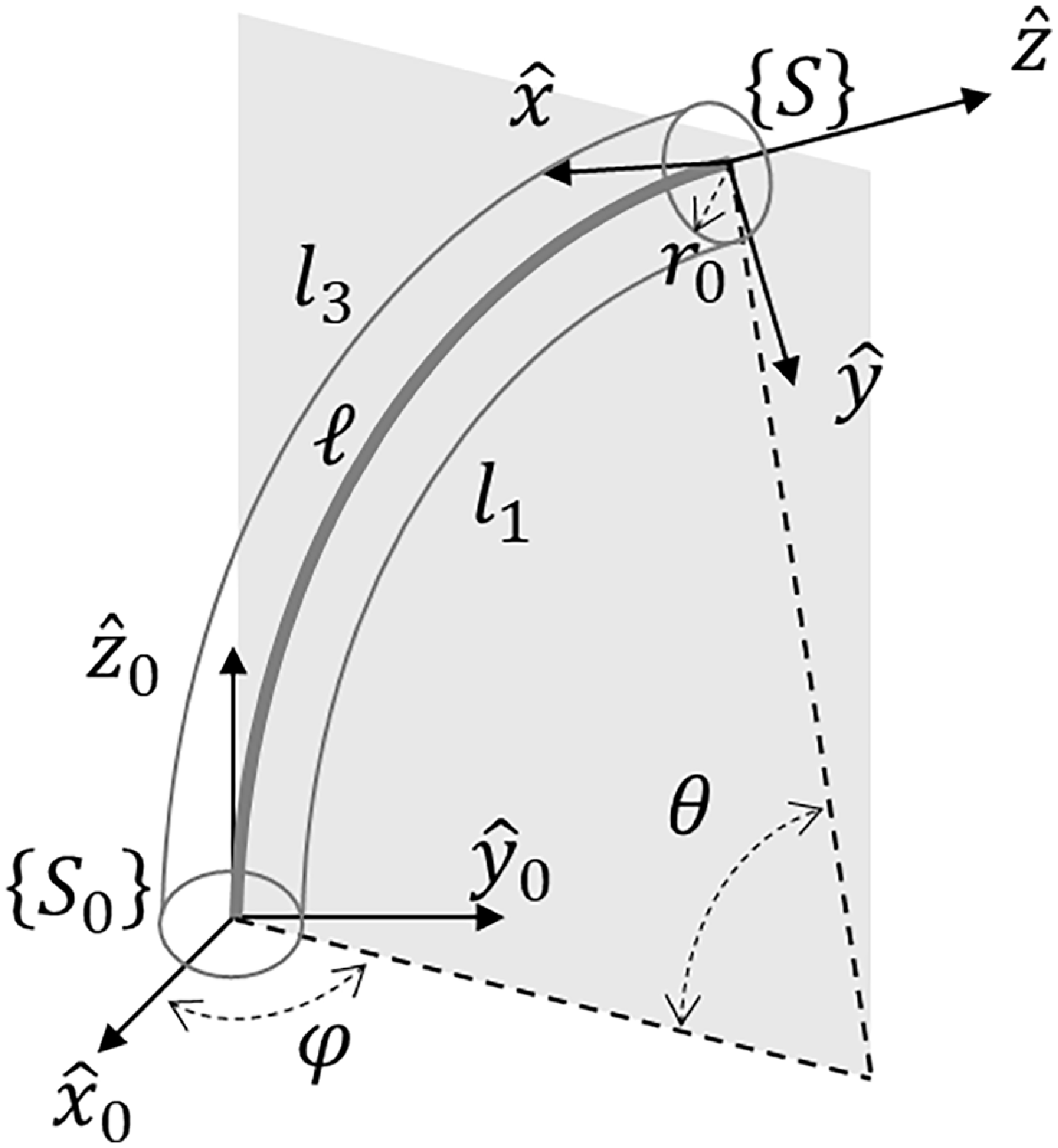
The robot has been modeled with piecewise constant curvature kinematics (PCCK), a common tool used in continuum and soft robotics [Reference Russo, Sadati, Dong, Mohammad, Walker, Bergeles, Xu and Axinte10]. Despite its limitations due to the lack of dynamic and material information on the robot, the model has been selected as the preferred tool in practical continuum robot applications because of its computational efficiency and scalability to multiple sections. PCCK describes the behavior of continuum robots by approximating the shape of their backbone to a circle arc. This assumption allows the definition of the backbone through two parameters only, namely, its angle of curvature
 $\theta$
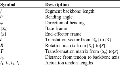
and the direction of bending φ (see Fig. 8 for a graphical representation and Table I for the complete nomenclature). PCCK formulations can also be used to link tendon lengths, which are the actuation variables
 $l_{1}$
,
 $l_{2}$
,
 $l_{3}$
, and
 $l_{4}$
, to the motion at the robot’s tip, defined by the frame
 $\{S\}$
with its center in
 $(x, y,z)$
in the base frame
 $ \{S_{0}\}$
. The homogeneous transformation
 $\boldsymbol{T}\in \textrm{SE}(3)$
from
 $\{S_{0}\}$
to
 $\{S\}$
can be expressed by
Piecewise constant curvature kinematic model for a tendon-driven continuum segment.

 \begin{equation}\textbf{T}\textbf{=}\left[\begin{array}{cc} \textbf{R} &\quad \textbf{t}\\ \textbf{0}_{\textbf{1}\times \textbf{3}} &\quad \textbf{1}_{\textbf{1}\times \textbf{1}} \end{array}\right],\end{equation}
where
 $\boldsymbol{R}\in \textrm{SO}(3)$
is the rotation and
 $\boldsymbol{t}\in \mathbb{R}^{3}$
is the translation along the segment arc. Parametrizing the motion by the bending angle
 $\theta$
and the direction of bending
 $\varphi$
, as illustrated in Fig. 8, the rotation from
 $ \{S_{0}\}$
to
 $\{S\}$
is
 \begin{equation}\boldsymbol{R}=\textrm{rot}_{z}\left(\varphi \right)\cdot \textrm{rot}_{y}\left(\theta \right)\cdot \textrm{rot}_{z}\left(-\varphi \right),\end{equation}
and the corresponding translation is
 \begin{equation}\boldsymbol{t}=\frac{l}{\theta } \left[\begin{array}{c} \cos \varphi \left(1-\cos \theta \right)\\ \sin \varphi \left(1-\cos \theta \right)\\ \sin \theta \end{array}\right],\end{equation}
where
 $l$
is the length of the backbone from {S} to {S0}. The transformation from bending angle and direction to tendon length can then be expressed as
 \begin{equation}\begin{cases} l_{1}=l-\theta r_{0}\sin \varphi \\ l_{2}=l+\theta r_{0}\cos \varphi \\ l_{3}=l+\theta r_{0}\sin \varphi \\ l_{4}=l-\theta r_{0}\cos \varphi \end{cases}\end{equation}
Nomenclature.

This kinematic model can be used to control the motion of the prototype.
5. Results and discussion
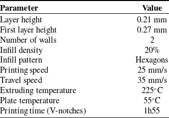
Each prototype has been printed in standard TPU 95A with a FlashForge Adventurer 5 M printer, using the printing parameters in Table II and a 0.4 mm nozzle. In preliminary prints, manufacturing quality has been observed to go down progressively during the print, due to vibrations of the backbone induced by the load of the nozzle onto the tip of the robot (acting as a cantilever beam). To reduce these vibrations, a rigid cylindrical scaffolding structure has been inserted halfway through the printing process to reduce the exposed height of the cantilever.
Printing parameters used for TPU 95A. Please note that these parameters are the results of the authors’ experience with the specific 3D printer, material, and design and might vary for different printers, filaments, and scales.

A circular indentation has been added to the base of all the prototypes (highlighted in blue in Fig. 5) to nest the PLA-printed scaffolding tube, as shown in Fig. 9. This option also helps minimize the need for support material, which negatively impacts the quality of the prototype with a difficult cleaning process afterward that could damage the print itself. Further, the automatic layout of the STL in the slicer tends to place the main bending planes of the robot corresponding to the X and Y axes of the printer, further amplifying the unwanted bending behavior. Therefore, a slight rotation of the prints around the Z-axis when preparing the g-code files has also been observed to diminish the impact of the vibrations on the quality of the prototypes.
Continuum robot prototyping: (a) The robot prototypes for the proposed designs (from left to right: the previous design from ref. [Reference Perugini and Russo34] printed in white TPU, helix, hourglass, T-notches, and V-notches). (b) The PLA scaffolding structure shown during the manufacturing of the helix design.

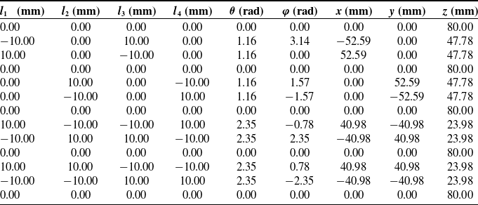
To test the designs, the robot was operated through its whole workspace, characterized by the middle and extreme points obtained by moving the servomotors in different combinations of their neutral, minimum, and maximum positions (0 mm, 10 mm, and -10 mm, respectively). The selected motion sequence contains thirteen positions, as detailed in Table III. Thanks to the kinematic model, implemented with MATLAB and used to define the trajectory in open-loop control, we have also obtained the curvature angle and the bending plane direction (θ and φ) for each of the thirteen configurations of the sequence, as well as the theoretical coordinates of the tip of the robots, which were then used for analysis. The behavior of the robot prototypes has instead been acquired with motion capture. To perform the acquisitions, each prototype has been attached to the actuation unit, which was then placed in an aluminum frame where cameras had been set to record the robot throughout the motion sequence in Table III, as illustrated in Figs. 10 and 11. We then used the images acquired during the experiments to extract the coordinates of the inner channel’s center through MATLAB in each configuration to compare them to the theoretical results.
Motion sequence in Cartesian, configuration, and actuation space.

Experimental setup for the top view acquisitions of the T-notch design.

Snapshots from a motion sequence of the V-notch design.

We tested the precision of each prototype by measuring repeatability in the center position (i.e., each motor set to 0 mm) throughout the open-loop motion sequence, obtaining five data points per cycle, with five motion cycles recorded per robot design, providing sufficient data for us to observe the efficiency of the designs. Motion was recorded both in top and side view but, given the kinematics of the system, the X and Y coordinates of the tip and sufficient to fully determine its Z coordinate as well, since it is fully coupled to the other coordinates as shown in Eq. (3). The views have been analyzed to extract the position of the distal point of the backbone through tip features, with image distortion and parallax compensated with a pixel-to-mm conversion at the base of the robot and at the tip through known geometrical features. The processed top views for an example design are presented in Fig. 12, with overall numerical results reported in Fig. 13.
Post-processed top view of the motion sequence for the hourglass design.

For the precision results in Fig. 13(a), we obtain means between 0.51 mm for the hourglass design and 1.48 mm for the V-notches design. However, we notice a higher repeatability for the V-notches design that presents a smaller standard deviation, contrary to the T-notches design that presents wider spread data, marking it as the design with the least repeatability. For the results in Fig. 13(b), we can observe that the experimental workspace is reduced compared to the one we expected with the PCCK model. Both results can be explained mainly by the manual attachment of the tendons to the motors, which can create a small slacking in the tendons, therefore reducing the precision and inducing a reduction of the workspace. Further causes of error include manufacturing errors during the printing process, with deformation induced by the vibrations mentioned earlier, as well as gravity-induced deformations, most notably in the T-notches design given its initial geometry. Additionally, the results could be less accurate due to image distortion and camera limitations during the acquisitions.
In the experiments, the robot prototypes show consistent behavior, as summarized in Table IV. The peak error is lower than 3.75% of the robot’s length in all designs, with a median error lower than 1.9%. These values compare positively to existing literature on tendon-driven robots, which reports error rates up to 10% of the backbone’s length [Reference Bishop, Russo, Dong and Axinte36–Reference Fang, Dong, Mohammad and Axinte38]. The V-notch design shows an overall higher error, whereas T-notches present a higher variability. Both hourglass and helix performed well from the position error perspective, but the hourglass design (together with the V-notch design) shows higher misalignment (error on direction of bending), clearly noticeable in Fig. 13(b) from the right (toward positive x) bending and reflected in the values in Table IV. From the results in Fig. 13(b), the area of the projection of the workspace on the XY plane of the prototypes has been compared to the ideal value obtained through PCCK, highlighting how the T-notches design, which performs satisfactorily in all other indicators, is the worst in performance, losing up to 41% of the ideal area (mostly attributable to tendon slacking). Overall, it is difficult to identify the best of the designs: the four prototypes behaved fairly similarly with respect to the selected key performance indicators, outperforming many other designs in terms of relative positioning error but showing a more limited performance in workspace and direction alignment. Additionally, we must note that although the comparison of the bending capabilities with PCCK is an effective way to characterize the kinematic behavior and the workspace of the proposed designs, further work is needed to identify the relationship between backbone stiffness and manufacturing parameters, with a focus on infill density and pattern in addition to design variations.
Design comparison.

Experimental results compared with the PCCK model simulation: (a) precision (median: red line; standard deviation: blue box; data range: black line); (b) workspace (top view).

6. Conclusions
In this paper, we presented four designs of TDCR, created to reduce the manufacturing cost as well as the assembly time, making them accessible to use as educational tools for continuum robotics, as well as encourage the development and uptake of this technology. The main contributions of the paper can be summarized as:
-
• The four proposed monolithic designs, which can be printed in a single part with TPU or other flexible material, highly reduce the cost and manufacturing/assembly time when compared to previous TDCR designs with segmented backbone and vertebrae while maintaining similar performance.
-
• A modular, easy-to-assemble actuation unit to actuate TDCR. This actuation unit design can also be printed or laser cut, making the manufacturing cost affordable, and relies on modular commercial components that allow for easy adaptation to different actuators, controllers, power supplies, and robot designs.
-
• The experimental characterization of the robot prototypes. Each design was tested through a sequence of 13 positions at the borders and in the center of the workspace; each sequence was repeated five times per prototype. The results highlight a peak error lower than 3.75% of the backbone’s length for all designs, with a median error lower than 1.9% (compared to errors up to 10% in literature with the open-loop control of a single segment).
However, we still note a decrease in expected workspace for the V-notches and T-notches due mainly to tendon slacking, as well as print quality in the case of the T-notches design. Future developments will be oriented toward improving tendon tension, which has been observed to be the key source of error. Even though tension control could be implemented, having hardware tensioners could solve tendon slacking in a much more reliable and effective way, also restoring part of the workspace loss observed with respect to the ideal PCCK model.
Supplementary material
The supplementary material for this article can be found at https://doi.org/10.1017/S0263574725102191.
Author contributions
CGK, NP, and MR conceived and designed the study. CK and NP designed and manufactured the prototypes and conducted data gathering. CK performed statistical analyses. CK and MR wrote the article.
Financial support
This research received no specific grant from any funding agency, commercial, or not-for-profit sectors.
Competing interests
The authors declare no conflicts of interest exist.
Ethical approval
Not applicable.