NOMENCLATURE
- AR(s)
aspect ratio(s)
- b,c
span and chord of the grid fin members, m
 $C_L$
,
$C_D$
,
$C_M$
coefficient of lift, drag and pitching moment
-
$C_{L_{\alpha}}$
lift versus angle-of-attack slope,
$deg^{-1}$
-
$C_{L_{max}}$
maximum lift coefficient
-
$C_{M_{\alpha}}$
moment versus angle-of-attack slope,
$deg^{-1}$
-
$\Delta C_L$
angle specific increase in
$C_L$
for the higher AR variant, %-
$\Delta C_{L_{avg}}$
averaged lift increment for the higher AR variant, %
-
$F_x$
,
$F_y$
,
$F_z$
force calculated along the three axes, N
- F/T
force-torque sensor
- g
gap between the grid fin members, m
- L, D
lift and drag forces, N
- MART
micro air vehicle aerodynamics research tunnel
-
$Ratio(C_{L_{max}})$
ratio of
$C_{L_{max}}$
of higher AR variant to the
$C_{L_{max}}$
of lower AR variant- Re
Reynolds number
-
$U_\infty$
freestream velocity, m/s
- UAV
unmanned aerial vehicles


Greek symbol
-
$\alpha (\alpha_s)$
angle-of-attack (angles of attack), deg
-
$\alpha_{max}$
stall angle, deg


1.0 INTRODUCTION
Missiles and unmanned aerial vehicles (UAVs) are self-guided intelligent weapon systems meant to carry payload or warhead to a deliberated location using an inbuilt guidance system. The guidance system sends steer and stabilisation commands to the control system which make use of external aerodynamic control surfaces to generate the specific manoeuvre. Thus, efficiency of their control system greatly depends on the efficiency of these control surfaces to produce the desired aerodynamic force. Therefore, intricate examination of these aerodynamic surfaces is imperative towards obtaining an efficient flight vehicle design. A recent accession to this technology aimed at improving the maneuverability have been termed the grid fins.
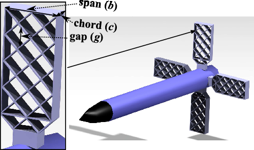
Grid fins are compact unconventional control surfaces consisting of a number of high aspect ratio (aspect ratio will be hereinafter represented as AR) planar members held together by an outer framework (Fig. 1). These fins have been utilised as control surfaces on numerous aerospace vehicles including missiles, smart bombs, launch escape spacecrafts, and reentry vehicles. Recently, these unconventional modern aero-mechanical technology-based aerodynamic surfaces have witnessed a steep upsurge in their application because of their superior structural and aerodynamic performances in comparison to the conventional monoplane fins (planar fins).
Missile with grid fins.

The concept of using a multi-planar geometry instead of a single large span control surface has been implemented since the inception of aircraft technology. In fact, aeronautic pioneers Santos Dumont and Horatio Phillips incorporated this technique in their first motorised flight attempts more than hundred years ago. Since the mid-1960s, Soviets (now Russia) utilised this concept of using a multi-planar control surface in the form of grid fins on a number of missiles and bombs like the SS-12 ‘Scaleboard’, AA-12 ‘Adder’ missile etc.(Reference Zaloga1). Henceforth, after the publication of the fundamental book on lattice fins titled ‘Wings with Internal Framework’(Reference Belotserkovskiy, Odnovol, Safin, Tyulenev, Frolov and Shitov2), these grate like control surfaces acquired global recognition and have been a topic of profound research globally. Hence, a technical know-how of some of the unique aerodynamic characteristics related to these fins were established which enabled their versatile applications in the defence and space industry. For instance, higher drag and stability enabled them to be used as drag brakes on the SOYUZ launch escape systems(Reference Pruzan, Mendenhall, Rose and Schuster3). Moreover, taking advantage of their stowability, light weight, and improved controllability at high angle-of-attack ( $\alpha$
) characteristics, these fins were affixed up on the USA Air Force based Massive Ordinance Air Blast (MOAB) missile(Reference Fulghum4) and the Quick-MEDS delivery system(Reference Yakimenko5). The characteristic of being rigid and efficient at higher speeds and steep angles of attack favoured their usage as re-entry hypersonic control surfaces on the SpaceX’s Falcon 9(6) reusable launch vehicle. These are also been explored for future solar system missions(Reference Palaszewski and Field7) and rockets(Reference Sreenivasulu and Sivaramakrishnan8). Recently, these were also implemented on a number of cruise missiles like the North Korean ‘Musudan’ missile(Reference Savelsberg and Kiessling9). The concept of utilising a bi-plane concept as proposed by Adolf Busemann, to reduce wave drag and sonic boom has also been studied for commercial supersonic flights(Reference Hu, Jameson and Wang10).
Since the early 1990s, much research has gone into contemplating the flow-physics linked to a grid fin’s unique aerodynamic characteristics in comparison to planar fins. The investigations involved experimental observations(Reference Washington, Booth and Miller11–Reference Hiroshima and Tatsumi18), theoretical analysis, and numerical computations. Theoretical investigations involved the application of Vortex Lattice Theory(Reference Brooks and Burkhalter19–Reference Theerthamalai22) and Prandtl-Meyer’s shock expansion theory(Reference Theerthamalai and Nagarathinam23). These were followed by Ledlow’s amalgamated incorporation of the pre-existing theoretical methods in association with a missile aerodynamic prediction tool and an ant colony optimisation technique to optimise the grid fin geometry(Reference Ledlow II, Burkhalter and Hartfield24). Additional investigations involved dynamic characteristic analysis using the small perturbation theory(Reference Zhaoqing and Hailong25) for aerodynamic prediction of the dynamic derivatives. Furthermore, numerical simulations were carried out for aerodynamic(Reference Sun and Khalid26–Reference Dikbas, Baran and Sert38), aeroelasticity(Reference Huang, Wen and Guowei39), and thermal(Reference Li, Jiang, Zhang and Peng40) analysis to acquire a more intricate in-sight into the underlying flow-physics, and hence carry out geometry optimisation for curtailed drag(Reference DeSpirito and Sahu30) and improved aerodynamic performance.
The expanded global acceptance of grid fins as control and stabiliser surfaces is associated with their exclusive advantages compared to the conventional planar fin counterparts. Some of them include their higher strength-to-weight ratio, efficient aerodynamic adaptability across wider Mach number regimes and for higher angles of attack (angles of attack will hereinafter be notated as  $\alpha_s$
), insignificant hinge moment requirements owing to their small chord(Reference Washington and Miller12,Reference Munawar36) , attenuated body vortex interference leading to improved roll control effectiveness(Reference Simpson and Sadler13,Reference DeSpirito, Vaughn and Washington31,Reference Yanushevsky41) , enhanced mobility(Reference Washington, Booth and Miller11) because of their foldability, and the increased target area due to their elevated manoeuvrability(Reference Ledlow II, Burkhalter and Hartfield24). Despite these benefits, their utility had been limited during the initial phases of their inception. This can be attributed to the combined effects related to (1) higher drag(Reference Washington and Miller12,Reference Dupuis and Berner15) because of their blunt structure, and (2) significantly deteriorated transonic flow performance due to the flow choking phenomena(Reference Fleeman42).
Owing to their higher drag and worsened transonic regime aerodynamic performance, considerable research had been carried out to alleviate these shortcomings. It was established in Ref. (Reference Washington and Miller12) that, drag can be tailored by implementing changes to the frame shape and cross-section, and hence realised a 25% reduction in the drag across subsonic and supersonic regimes. However, most alterations were carried out to enhance transonic and supersonic performance. Sweeping the leading edges of individual cells called as local sweeping amounted to a drag reduction of 38% in the supersonic domain(Reference Guyot and Schülein43). Sweeping back the framework of grid fin cells in the chord direction called the sweptback grid fin(Reference Zeng, Cai, Debiasi and Chng44,Reference Cai45) inferred a drag reduction of  $12\%-13\%$
in the transonic regime. The combination of sharp leading edges and sweptback grid fins displayed a transonic drag reduction of
 $25\%-30\%$
(Reference Debiasi46,Reference Debiasi and Zeng47) . A study related to single cell leading edge variation(Reference Dan and Yong48) in the transonic flow established a drag reduction of
 $\approx\!40\%$
while using a delta configuration. Incorporating an optimised Busemann profile cross-section for the grid fin cells has also been suggested to reduce drag in the transonic and supersonic regimes by virtue of the wave cancellation effect(Reference Despeyroux, Hickey, Desaulnier, Luciano, Piotrowski and Hamel37).
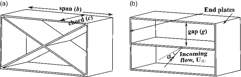
Most of the analysis carried out earlier were aimed at alleviating the drag associated with transonic and supersonic regimes. However, numerous applications related to UAVs and missiles operate in the subsonic regime. Hence, critical understanding with respect to the effects of different geometrical parameters can be used to improve subsonic performance which would lead to increased advantages in this regime. Some critical geometrical parameters effecting the grid fin aerodynamics are the cell spacing, chord, span, thickness, and cross-section of the members. Current study aims at establishing the effects of individual geometrical parameters on the overall aerodynamics of grid fins in the subsonic regime. The inferences drawn from these investigations can be collated to achieve the most optimum grid fin geometry based on stall angle, maximum lift and aerodynamic efficiency (lift to drag ratio) requirements. The study makes use of a simplified grid fin variant called the cascade fin (hereinafter referred to as grid fins)(Reference Misra49–Reference Tripathi, Misra and Sucheendran52). It is derived from grid fins (Fig. 2(a)) by removing the internal cross members or diagonal members while retaining the horizontal lifting members (Fig. 2(b)). The uncomplicated structure of this grid fin variant enables explicit examination of the different geometrical parameters, and hence carry out geometry optimisation. Misra(Reference Misra49) carried out extensive experimental analysis at subsonic speeds and low Reynolds number ( $Re=2.6\times10^5$
) on these fins and emphasised their elevated high
 $\alpha$
performance by providing a significantly delayed stall angle. However, higher drag accounted for the appreciably lower aerodynamic efficiency for these fins up to
 $\alpha=25^{\circ}$
(most operable
 $\alpha$
region for control surfaces) compared to planar fins. It was also established that an increase in the gap-to-chord ratio (g/c) by increasing the gap (g) leads to hastened stall and an increase in the overall lift. This apparent increase in the lift leads to a subtle increase in the aerodynamic efficiency within the
 $\alpha$
region corresponding to
 $0^{\circ}$
–
 $20^{\circ}$
. The results were further corroborated through comprehensive numerical analysis performed by the authors in Ref. (Reference Tripathi, Mahesh and Misra53). These investigations lead to a greater understanding of the underlying flow-physics associated with these trends. Further analysis with respect to replacing the rectangular cross-section lifting member plates with NACA 0012 cross-section members established an appreciable enhancement in the aerodynamic efficiency (maximum gain of 60%) at the expense of steeper and hastened stalling characteristics(Reference Tripathi, Misra and Sucheendran52). It was emphasized in Ref. (Reference Misra49) that, vertical members had minimal impact on the lifting characteristics of the grid fins. However, inclusion of these members would lead to an increase in the overall drag. This drag advancement lead to further aerodynamic efficiency reduction. The study carried out by Misra(Reference Misra49) related to effect of increasing number of planar members established lift increment at the expense of reduced aerodynamic efficiency because of the higher drag value. As a part of the concerted effort to enhance grid fin aerodynamic efficiency, investigations pertaining to AR variation were carried out henceforth, which has been presented in the current paper.
Comparison of grid fin and cascade fin (a) grid fin (b) cascade fin.

Aspect ratio (AR) for a lifting surface is the ratio of its squared span value and its projected area. For a constant chord surface, it becomes the ratio of its span and the chord. Before proceeding on to the discussions related to effect of AR variation on grid fin aerodynamics, a brief understanding with respect to the effect of AR variation for planar fins will be helpful in analyzing the results pertaining to grid fins. The influence of AR in the case of planar fins had been found to be significantly high compared to other geometrical parameters especially at low Re as observed earlier by many authors(Reference Gabriel and Mueller54–Reference Mizoguchi and Itoh56). It had been found to significantly impact the maximum lift coefficient ( $C_{L_{max}}$
) and the stall angle. Reference(Reference Okamoto and Azuma55) stated the presence of higher maximum lift at higher stall angles for lower AR wings. Moreover, the study inferred the presence of an added non-linear lift component for lower AR wings, which was stronger in strength at higher angles. The flow-physics associated with these trends were explained by the presence of flow escaping from the lower surface towards the upper surface for lower AR wings. This lead to reduction of the flow separation over the upper surfaces (leading to the delayed
 $\alpha_{max}$
) as well as formation of a low pressure region on the upper surface due to the wing-tip vortices. This generated the aforementioned non-linear lift component at higher angles. Notably, it was the combination of this non-linear lift and linear lift components (linked to the potential lift which should be higher for higher AR) which lead to the aforementioned aerodynamic deviations between wings(Reference Gabriel and Mueller54) of different AR. The analysis further described tangible deviations between the aerodynamics associated with monoplane wings of low AR (
 $AR<2$
) and high AR (
 $AR\geq2$
) variants. Since grid fins consist of multiple lifting surfaces placed adjacent to each other, it becomes imperative to analyse the impact of their AR, and hence assist in determining optimal grid fin geometry for enhanced aerodynamic efficiency along-with an improved or comparable high
 $\alpha$
performance. Analysis pertaining to AR variation for grid fins in a later section has been carried out keeping these points into consideration.
The current paper ventures upon experimentally studying the impact of varying the lifting member AR of grid fins by virtue of span alteration at subsonic speed, which in the author’s knowledge has not been studied earlier. Moreover, owing to the increased influence of g/c parameter on grid fin stall and lifting characteristics as established earlier by the authors in Ref. (Reference Tripathi, Mahesh and Misra53), AR variation is analysed for different g/c variants. The study makes use of data related to force and moment coefficients for different grid fin configurations. These investigations make use of the cascade type grid fin geometry (mentioned earlier) termed as cascade fins(Reference Kumar, Misra and Ghosh50) consisting of a cascade of three lifting members placed adjacent to each other at a specified distance from each other. As stated earlier, such a geometry enabled explicit examination of different geometrical parameters by varying them independently, and hence decipher the respective aerodynamic impacts thereof. The choice concerning selection of three lifting members was a conservative decision based on alleviating the blockage effect as more number of planes would lead to a bigger model leading to increased blockage. Moreover, inferences related to minuscule impact of vertical members on the lifting characteristics(Reference Misra49) and reduction in aerodynamic efficiency lead to the usage of cascade geometry without vertical members. Work carried out in the present paper, can be used to collectively elucidate the impact of cell AR and g/c parameter on the grid fin aerodynamics. It is to be noted that, the inferences drawn out from the study made use of force and moment data only. However, the lack of flow visualisation data is a noteworthy limitation of this study.
2.0 EXPERIMENTAL SETUP
2.1 MART wind tunnel
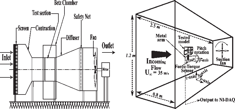
Experiments were performed at micro air vehicle aerodynamics research tunnel (MART) facility situated at CSIR-NAL Bangalore, India (Fig. 3(a)). The tunnel is a suction-type subsonic tunnel consisting of an interchangeable open and closed test section configuration. Hence, based on the physical requirements of the model being tested, the experiments can be performed in an open or closed test section. The tunnel has a wide a range of applications because of this feature. Details of the open jet configuration can be found in the literature(57). Current investigations make use of the closed jet test section with the dimensions being  $0.8 \times 1.2 \times 2.5\textrm{m}$
(Fig. 3(b)). The tunnel is characterised by low turbulence with a measured turbulence level less than 0.15% and has been specifically designed for carrying out experiments in low Re flows. The tunnel incorporates a settling chamber composed of a sequence of screens and honeycomb consisting of high AR square cells followed by a contraction zone providing a contraction ratio of 9:1. Consequently, the tunnel is able to provide flow uniformity with the mean velocity ranging between
 $\pm0.1\%$
and the angularity within
 $0.1^{\circ}$
for the incoming flow (
 $U_\infty$
). The experimental freestream velocity of 35m/s was accomplished by a 12 bladed, belt-driven suction fan powered by a 45kW motor rotating at 1450RPM. Notably, the suction fan drawn in Fig. 3(b) is for representation purpose only.
Wind tunnel model and closed-jet test section configuration (a) schematic representation of MART wind tunnel (b) wind tunnel measurement setup.

2.2 Instrumentation
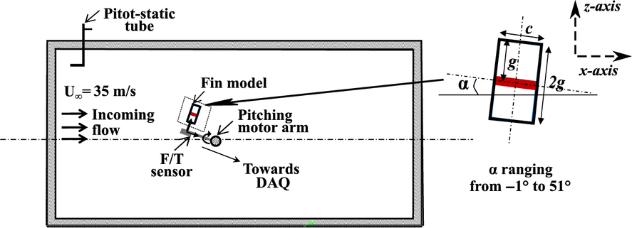
Dynamic pressure was measured using a pitot-static tube, which was placed appropriately upstream of the geometry in the test section (Fig. 4). The pertinent pressure variation was read upon using a manometer. Blockage based on the ratio of projected frontal area of the model across different AR variants to the area of the test section was found to be less than 1.7% even up to the maximum  $\alpha$
. Thus, the impact related to wall interference was appreciably low on the final results, and hence no wall effect correction was applied to the experimental data. Since, the experiments required high
 $\alpha$
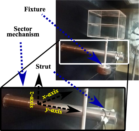
variations, a specially designed sector mechanism consisting of a metal arm (Fig. 5) attached to a Siemens make programmable motor, and an in-house LabVIEW program were used to emulate the pitching rotation. A sting was attached to the metal arm with the other end affixed to a six-component ATI make mini40 force-torque sensor (F/T). The later was used to acquire instantaneous force and torque load values. The sensors had a force range of 40N in the x and y-directions, 120N in the z-direction along with a resolution of 1/50N in the x and y-directions and 1/25N in the z-direction (See Figs 3(b) and 4 for axis clarifications). Similarly, sensor’s torque sensing range and resolution were 20 and
 $1/2000\textrm{N}-\textrm{m}$
, respectively about all the axes. The models were rigidly fixed upon a fixture using a pair of threaded screws. The other end of the fixture rod was attached atop the F/T sensor.
Schematic representation of customised sting setup for high angle-of-attack pitching.

Sector mechanism designed to emulate angle-of-attack rotation, bottom image is a zoomed version of the sector mechanism used for wind tunnel experimentation.

Measurements were performed with the  $\alpha$
varying between
 $-1^{\circ}$
and
 $51^{\circ}$
at the rate of
 $25^{\circ}$
per minute, using a continuous sweep method in the wind-on and wind-off conditions. Sensor output retrieved data at a sampling rate of 500Hz in-sync with the model pitching and was fed to a National Instruments Data Acquisition (NI-DAQ) board. Here data reduction was achieved by time averaging the acquired data for every
 $0.1^{\circ}$
rotation using an in-house MATLAB program. Uncertainty analysis evaluated using the Root of Sum of Squared technique established an uncertainty of less than 2% for the force and moment measurements. Separate measurements were carried out in the wind-on and wind-off conditions for the setup without the model to remove the adapter tare from the results. The wind-off measurements were subtracted from the final results to remove the errors associated with movement of the setup. Test conditions pertaining to the experiments were as follows:
Reynolds number
$ (Re) =2.09\times10^5$
(based on chord length of the models)Freestream velocity of the incoming flow
$ (U_\infty) =35\textrm{m}/\textrm{s}$
Mach number = 0.102
angle-of-attack
$ (\alpha) = -1^{\circ}$
to
$51^{\circ}$


The F/T sensor evaluated  $F_x$
,
 $F_z$
and
 $T_y$
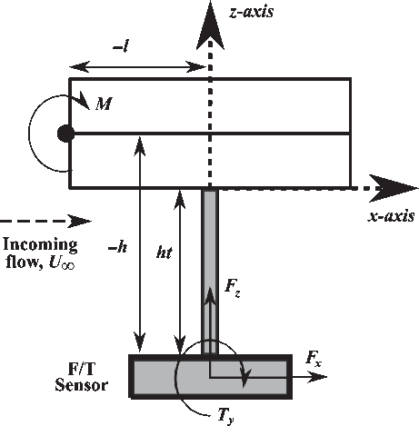
data. Hence, further transformations were required to evaluate the pertinent lift (L)- drag (D) forces and moment (about the leading edge of the middle member, M) values. Based on Fig. 6, equations pertaining to coordinate transformation required to calculate these values are as follows:
 \begin{eqnarray}L &= &F_zcos\alpha - F_xsin\alpha \end{eqnarray}
 \begin{eqnarray}D &=& F_zsin\alpha + F_xcos\alpha \end{eqnarray}
 \begin{eqnarray}M&=&T_y + (F_x\times h)+(F_z\times l) \end{eqnarray}
where,  $h\approx ht+g$
,
 $ht=109.5\textrm{mm}$
,
 $l=chord/2=50\textrm{mm}$
.
Transformation coordinates to calculate the lift force, drag force, and moment about the leading edge of the middle lifting member.

2.3 Experimental models
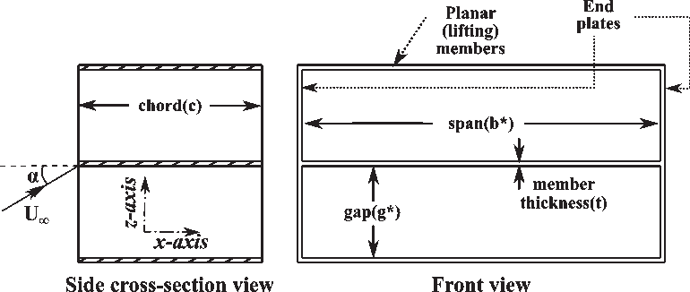
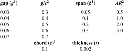
In the present study, examination on the effect of AR variation for different g/c grid fins was carried out by making use of the aforementioned cascade type grid fin variant (hereinafter referred to as grid fins only). All the models consisted of three rectangular cross-section lifting members with same chord (c) length (Fig. 7). It is noteworthy that this geometry (consisting of three members) was selected based on the wind tunnel blockage constraints. The distance between these members called the gap (g) is varied across all the AR variants. This variation is represented in the form of g/c parameter. Structural rigidity is provided by the end plates. Earlier studies carried out by Misra(Reference Misra49) inferred the mitigated impact of vertical members on the lifting characteristics alongside reduced aerodynamic efficiency for grid fins when pitching rotation is considered. Notwithstanding this, the vertical members other than end plate members were removed from the geometry in the current study to ascertain elimination of their impact, and hence assist in exclusively deciphering the effects associated with span (b) variation. Dimensions pertaining to the various geometrical parameters presented in Fig. 7 are given in Table 1:
Geometrical parameters of cascade type grid fins (*variable).

Geometric dimensions

1Dimensions in m
2Non-dimensional value
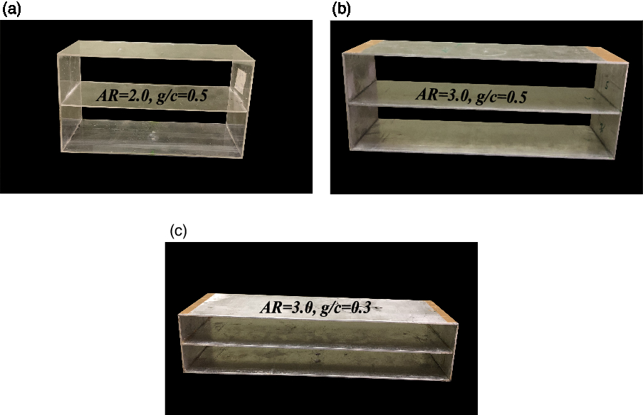
In total, 20 models corresponding to 4 different AR and 5 different g/c combinations were tested during the analysis. All models with AR less than two were manufactured using acrylic sheets and the fins with AR more than or equal to two were made using aluminum sheets (Fig. 8). The sheets were accurately cut as per the specified dimensions using a laser cutting machine. Force and moment non-dimensionalization was carried out using projected area of the respective AR variant as the reference area and c (constant) as the reference length, respectively.
Models manufactured using acrylic or aluminium sheets (a) acrylic model for low AR grid fins (b) aluminium model for high AR grid fins (c) aluminium model for high AR grid fins and lower g/c.

3.0 RESULTS AND DISCUSSIONS
3.1 Effect of varying gap between the members on the aerodynamic coefficients
Current section discusses the effect of g/c variation (by virtue of g alteration) on grid fin aerodynamics while retaining the AR of the three planar members constant at  $AR=2.0$
. It is noteworthy that this study is similar to the one carried out numerically by the authors in Ref. (Reference Tripathi, Sucheendran and Misra51). A comparison of the results obtained in this section with the results presented in Ref. (Reference Tripathi, Sucheendran and Misra51) can be useful in determining the qualitative accuracy of the results obtained during the current investigations.
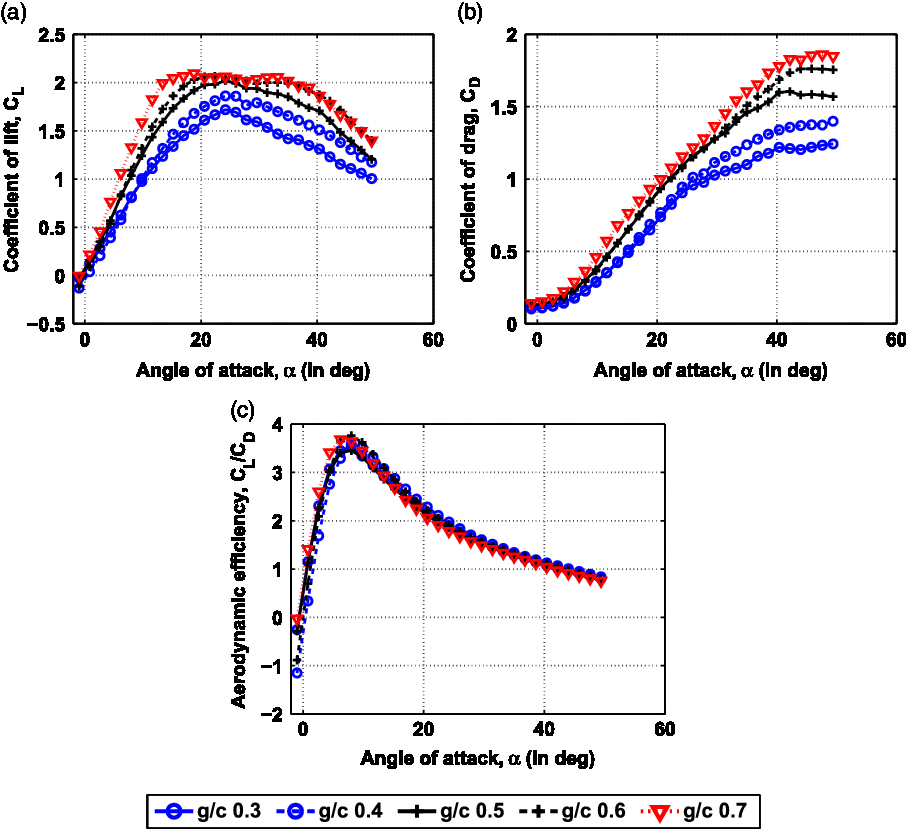
Figure 9 shows the effect of g/c variation on the pertinent aerodynamic coefficients. As seen in Fig. 9(a), increasing  $\alpha$
leads to the increase in lift coefficient (
 $C_L$
). Subsequently, the angle up to which
 $C_L$
increases called the stall angle or
 $\alpha_{max}$
(minimum at
 $\alpha=21.9^{\circ}$
for
 $g/c=0.7$
) is significantly higher compared to conventional fins whose
 $\alpha_{max}$
has been derived to occur at
 $\approx\!12^{\circ}$
. The trends also embody a gradual post-stall drop in lift for all the g/c variant grid fins, unlike the abrupt stall behaviour of conventional fins. These characteristics are indicative of the enhanced manoeuvrability provided by these fins. These plots further demonstrate the fact that, g/c decrement leads to the increase in
 $\alpha_{max}$
alongside a reduction in the values pertaining to
 $C_L$
versus
 $\alpha$
slope (
 $C_{L_\alpha}$
) and maximum lift coefficient (
 $C_{L_{max}}$
). The effect leading to these variations for the lower g/c variants had been termed as cascade effect in earlier studies carried out by the authors in Ref. (Reference Tripathi, Mahesh and Misra53) This effect, as discussed in Ref. (Reference Tripathi, Misra and Sucheendran52) is a result of the interference between the flow corresponding to the neighbouring members.
Variation of aerodynamic coefficients for different g/c at different  $ \alpha_{\text{{s}}}$
for
 $ \textit{AR = 2.0}$
(a) variation of lift coefficient versus angle-of-attack for different g/c (b) variation of drag coefficient versus angle-of-attack for different g/c (c) variation of aerodynamic efficiency versus angle-of-attack for different g/c.

Coefficient of drag ( $C_D$
) reduces as g/c reduces (see Fig. 9(b)) and deviation between the various grid fins are higher at higher angles (
 $\alpha>25^{\circ}$
). This is again associated with the increase in cascade effect as g/c reduces leading to increased flow acceleration between the members, and hence the reduced pressure drag due to mitigated flow separation(Reference Tripathi, Misra and Sucheendran52). Since drag emanating due to flow separation is higher at higher angles, differences associated with mitigated flow separation due to cascade effect become more appreciable at higher angles. This amounts to the increased deviation between various g/c grid fins at higher angles.
The ratio of lift and drag coefficients ( $C_L/C_D$
) termed as aerodynamic efficiency is a critical parameter while selecting the design parameters of an aerodynamic control surface. A higher ratio would lead to elevated lift (leading to increment in the payload carrying capacity) alongside assuaged drag (reduction in the thrust requirement causing weight mitigation). This value is found to be comparable for all the variants (Fig. 9(c)). However, a subtle efficiency reduction is realised for the lower g/c variant in the most operable
 $\alpha$
range. At angles beyond
 $\alpha=20^{\circ}$
,
 $C_L/C_D$
values pertaining to the different g/c variants progressively converge towards each other. This further shows the increased aerodynamic performance of grid fins (compared to planar fins) at higher angles by providing a significantly higher
 $\alpha_{max}$
alongside comparable aerodynamic efficiency. Thus, gap selection would necessarily alter the overall
 $\alpha_{max}$
, and lift pertaining to grid fins. Aerodynamic efficiency undergoes meagre variation across different g/c variants in the most operable
 $\alpha$
range.
The study underscores the impact of g/c variation on grid fin aerodynamics leading to delayed  $\alpha_{max}$
, reduced maximum lift, and subtle efficiency reduction for lower g/c. Qualitatively, these variations are similar to the ones observed earlier in references(Reference Misra49,Reference Tripathi, Misra and Sucheendran52,Reference Tripathi, Mahesh and Misra53) . Thus, the trends associated with experimental data pertaining to g/c variation comprehended in this study conform well with the pre-existing data. Notably, this could be an essential factor while assessing the accuracy of the trends related to AR variation. Comparison of the aforementioned trends for g/c variation (especially
 $C_L/C_D$
) in relation to those established for AR variation (covered in the following sections) will be helpful in fine tuning these parameters.
3.2 Effect of aspect ratio variation on grid fins with different gap-to-chord ratios
After analysing the effect of gap variation on the grid fin flow characteristics, further analysis was carried out to comprehend the impact of AR variation by varying b of the three planar members while keeping the c constant. The particular analysis has been carried out for different g/c variants. Hence, this section relates the aerodynamics associated with different AR grid fins evaluated for different g/c.
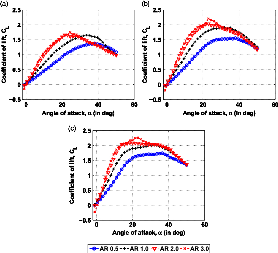
Variation of lift coefficient with angle-of-attack for different ARs across grid fins of different g/c (a)  $ \textit{g/c = 0.3}$
(b)
 $ \textit{g/c = 0.5}$
(c)
 $ \textit{g/c = 0.7}$
.

3.2.1 Lift coefficient (
$${C_L}$$
)

Figure 10 compares the effect of AR variation on  $C_L$
for different g/c values (
 $g/c=0.3$
, 0.5, 0.7). As seen in Fig. 10(a) for
 $g/c=0.3$
,
 $C_L$
is higher for higher AR up to
 $\alpha=22^{\circ}$
. This can be quantified by calculating the increment in value called as lift increment (notated as
 $\Delta C_L$
). This is calculated by using the Equation (4).
 \begin{equation}\Delta C_L=(C_{L_{higherAR}}-C_{L_{lowerAR}})/C_{L_{lowerAR}}\times 100\end{equation}
where,  $C_{L_{higherAR}}$
and
 $C_{L_{lowerAR}}$
are the values of
 $C_L$
corresponding to higher and lower AR variants, respectively at specific
 $\alpha_s$
. These values are further averaged based on the number of angles to calculate the averaged lift increment (
 $\Delta C_{L_{avg}}$
). Based on this,
 $\Delta C_{L_{avg}}$
across all the angles was found to be 15.28%, and 20.27% for
 $AR=1.0$
and
 $AR=3.0$
, respectively in comparison to
 $AR=0.5$
. The increase in lift for higher AR at low angles can be linked to the increase in circulation lift component (linear lift component) as well as increased lift favourable cascaded surface area for higher AR. Consequently,
 $C_{L_{max}}$
is higher for higher AR. Thus,
 $C_{L_{max}}$
values for
 $AR=1.0$
and 3.0 are found to be 1.2 times and 1.3 times, respectively in comparison to the
 $C_{L_{max}}$
value pertaining to
 $AR=0.5$
. High AR leads to the increased lift slope (notated as
 $C_{L_\alpha}$
), earlier
 $\alpha_{max}$
, and a steeper post-stall drop in
 $C_L$
. For instance, in the case of
 $AR=0.5$
,
 $\alpha_{max}$
exists at
 $\alpha=38^{\circ}$
, whereas, for
 $AR=3.0$
it is present at
 $\alpha=24.5^{\circ}$
. This indicates the presence of reduced flow separation associated with lower AR grid fins leading to higher
 $\alpha_{max}$
. Beyond
 $\alpha=30^{\circ}$
, the steeper drop in lift for higher AR leads to the higher
 $C_L$
values for
 $AR=0.5$
and 1.0 compared to
 $AR=2.0$
and 3.0. Thus, high
 $\alpha$
lifting performance defined by flatness of the post-stall drop in lift as well as overall lift value beyond
 $\alpha_{max}$
, is better for the low AR grid fins with
 $g/c=0.3$
. It can be noted that, for the high AR grid fins, the drop in lift is steeper for
 $AR=3.0$
. This reaffirms the reduction in controllability at higher
 $\alpha_s$
for increased AR.
Similar assertions related to lower  $C_{L_\alpha}$
and delayed stall due to lower AR are presented by plots pertaining to
 $g/c=0.5$
and 0.7 cases in Figs 10(b) and 10(c), respectively. For instance, angle (
 $\alpha$
) corresponding to maximum
 $C_L$
(
 $C_{L_{max}}$
) was found to be at
 $\alpha=36.5^{\circ}$
for
 $AR=0.5$
compared to
 $\alpha=23^{\circ}$
for
 $AR=3.0$
in Fig. 10(c). It is also noteworthy that, as a consequence of reduced cascade effect for higher g/c, slope of respective AR plots are seen to be higher for higher g/c leading to higher
 $C_{L_{max}}$
. However, while comparing the plots for a specific g/c, difference between
 $C_L$
at higher angles pertaining to different AR reduces as g/c increases. This leads to the smaller or similar
 $C_L$
for
 $AR=0.5$
or 1.0, respectively compared to
 $AR=2.0$
and 3.0 for
 $g/c=0.7$
at steep angles. Moreover, differences between the high AR fins against low AR fins reduce for higher g/c especially at angles beyond
 $\alpha=40^{\circ}$
. In-fact, for
 $g/c=0.7$
, lift of
 $AR=2.0$
and 3.0 are seen to be comparable to that of
 $AR=1.0$
beyond
 $\alpha=40^{\circ}$
(Fig. 10(c)). It can also be asserted that, the difference in post-stall flatness between the low AR grid fins and high AR fins reduces for higher g/c. This indicates the reduced influence of phenomena associated with improved post-stall performance for lower AR and the qualitative deviation between high AR and low AR fins at high
 $\alpha_s$
due to increased gap. Earlier study comparing different AR wings in Ref. (Reference Gabriel and Mueller54) presented an increase in
 $C_{L_{max}}$
for lower AR due to the lift induced by wing-tip vortices escaping to the upper surfaces at high
 $\alpha_s$
. Contrarily,
 $C_{L_{max}}$
in the case of grid fins is lesser for smaller AR. Further in-sight into the phenomena associated with the aerodynamic deviations related to lower
 $C_{L_{max}}$
for lower AR grid fins as well as reduced differences between the various AR variants (especially at high
 $\alpha_s$
) for higher g/c have been discussed later in Section 3.3.
Similar to the monoplane wings, a notable disparity can be observed in the deviation of  $C_L$
between the low AR grid fins (
 $AR=0.5$
and 1.0) compared to those between the high AR grid fins (
 $AR=2.0$
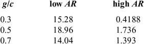
and 3.0) with the latter being significantly lower. This difference can be further contemplated in Table 2 wherein, the average difference in
 $C_L$
between the high AR fins and the low AR fins have been evaluated for different g/c. This table also displays increased variation between the low AR grid fins.
Differences in  $${C_L}$$
across all angles for the low AR and high AR grid fins

3.2.2 Maximum lift coefficient (
$${{\bf{C}}_{{{\bf{L}}_{{\bf{max}}}}}}$$
) and stall angle (
$${{\bf{\alpha }}_{{\bf{max}}}}$$
)


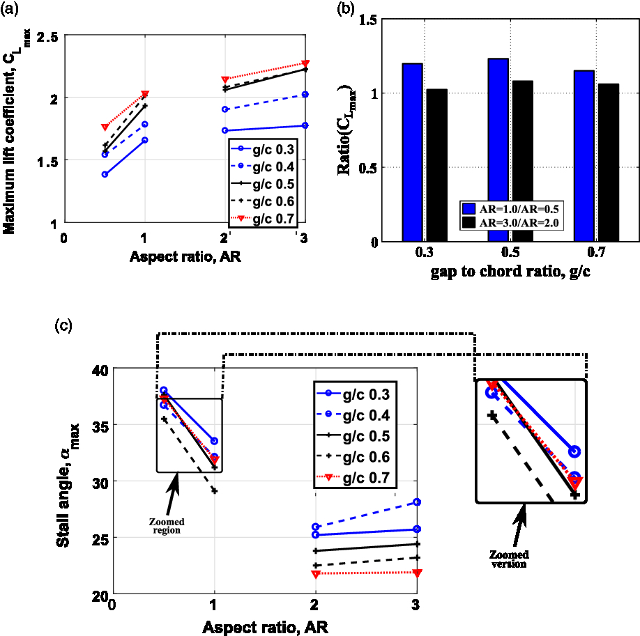
Averaged increment in  $C_{L_{max}}$
between all g/c pertaining to 0.3–0.7 was found to be 1.2 times for the higher AR variant (
 $AR=1.0$
) in the case of low AR grid fins, and 1.05 times in the case of high AR fins (Fig. 11(a)). This can be further established from Fig. 11(b) wherein, the increment in maximum lift for the higher AR grid fin is plotted for the two AR regimes at
 $g/c=0.3$
, 0.5 and 0.7 using a bar plot. This increment is represented as
 $Ratio(C_{L_{max}})$
with the ratio calculated by dividing the
 $C_{L_{max}}$
of the higher AR variant by the lower AR variant within the high and low AR regions, respectively. For instance, in the low AR region,
 $Ratio(C_{L_{max}})$
is evaluated by taking the ratio of
 $C_{L_{max}}$
of
 $AR=1.0$
and
 $AR=0.5$
. As seen in the figure, this ratio is higher for the low AR grid fins for all the g/c values.
Variation of maximum lift coefficient and stall angle with AR across grid fins of different g/c (a) maximum lift coefficient versus AR for different g/c (b) ratio of  $\text{{C}}_{\text{{L}}_{\text{{max}}}}$
for the higher AR variant to the lower AR variant within the two AR regimes (c) stall angle versus AR for different g/c.

Similarly,  $\alpha_{max}$
deviation was higher between the low AR fins (average deviation of
 $4^{\circ}$
) compared to an average deviation of
 $\approx1.5^{\circ}$
between the high AR grid fins as observed in Fig. 11(c). Based on these results, it can be envisaged that, within the low AR grid fins, aerodynamic characteristics drastically change as AR reduces with the reduction leading to increased
 $\alpha_{max}$
and reduced maximum lift. It is known from previous studies(Reference Tripathi, Misra and Sucheendran52) that, flow separation over the uppermost and lowermost members govern the overall
 $\alpha_{max}$
for such cascade type grid fin configurations. Thus, from the aforementioned plots, it can be stated that, AR variation leads to flow separation differences over these members causing the aforementioned
 $\alpha_{max}$
deviations.
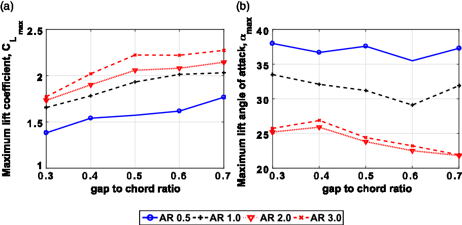
Figure 12 analyses the effects related to g/c variation by plotting  $C_{L_{max}}$
and
 $\alpha_{max}$
against the respective g/c variant at several aspect ratios (ARs). As seen in Fig. 12(a),
 $C_{L_{max}}$
goes on reducing as g/c reduces due to the increased cascade effect. This effect leads to a reduction in the pressure differential across the upper and lower surfaces of the members, and hence a reduction in the
 $C_{L}$
. This effect increases as g/c reduces, and hence the mitigated value of
 $C_L$
for lower g/c. In Fig. 12(b),
 $\alpha_{max}$
increases with g/c reduction between
 $g/c=0.4-0.7$
for
 $AR=2.0$
and 3.0. As reported in Ref. (Reference Tripathi, Sucheendran and Misra51), reasons for this increment can be associated with the reduction in cascade effect for lower g/c leading to increased flow acceleration between the members. Hence, flow separation over the cascaded upper surfaces (the surfaces surrounded by neighboring member) reduces for lower gaps, and hence the delayed
 $\alpha_{max}$
. However, certain discrepancies can also be observed which are:
1. A subtle increase in
$\alpha_{max}$
from
$g/c=0.3$
to 0.4 can be discerned for
$AR=2.0$
and 3.0.2. The value corresponding to
$\alpha_{max}$
reduces with g/c increment for
$AR=1.0$
up to
$g/c=0.6$
and increases at
$g/c=0.7$
. The trend is similar for
$AR=0.5$
with a subtle increment at
$g/c=0.5$
. However, for most cases it reduces up to
$g/c=0.6$
and increases beyond
$g/c=0.7$
.


Variation of maximum lift coefficient and stall angle for different configurations (a) variation of maximum lift coefficient with g/c alterations for several ARs (b) variation of angle-of-attack pertaining to maximum lift coefficient with g/c alterations for several ARs.

The reasons leading to these deviations can be linked to the combined effects of improved flow alignment for higher g/c (Reference Tripathi, Misra and Sucheendran52) as well as the reduced flow separation on the uppermost member for lower AR (as indicated earlier). For the first case, due to the higher AR, flow separation will be higher. However, the flow alignment is better for  $g/c=0.4$
in comparison to
 $g/c=0.3$
. Since, the impact of this improved alignment would be higher due to the bigger span, the effective
 $\alpha_{max}$
improves at
 $g/c=0.4$
for
 $AR=2.0$
and 3.0. For
 $AR=0.5$
and 1.0, flow separation deviation is similar to normal cascade effect trends up to
 $g/c=0.6$
with higher g/c leading to lower
 $\alpha_{max}$
. However, beyond
 $g/c=0.6$
, due to the combination of reduced flow separation for a lower AR and the effect associated with improved flow alignment for higher g/c,
 $\alpha_{max}$
increases between
 $g/c=0.6-0.7$
.
Notably, the difference between  $AR=0.5$
and 1.0 (low AR fins) grid fin plots are significantly higher compared to the deviation between the
 $AR=2.0$
and 3.0 grid fin plots (high AR fins). This is again indicative of the qualitative aerodynamic differences between the low AR fins and the high AR fins (analogous to the observations noted in Ref. (Reference Gabriel and Mueller54) for planar fins). It is noteworthy that, further experiments need to be carried out for other AR variants to further validate these inferences. It can also be noted that, current analysis made use of three lifting members. Hence, an approach towards carrying out similar analysis for different number of planar members would lead to greater understanding with respect to AR variation impacts on
 $C_L$
and
 $\alpha_{max}$
.
Based on this analysis, it can be asserted that,  $C_{L_{max}}$
(higher for higher g/c and AR) and
 $\alpha_{max}$
(higher for lower g/c and AR) requirements would govern the final AR and g/c selection for grid fin geometry optimisation.
3.2.3 Drag coefficient (
${\textbf{C}}_{\textbf{D}}$
)

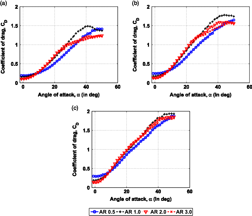
Figure 13 compares  $C_D$
for different AR with specific g/c values that is,
 $g/c=0.3$
(Fig. 13(a)),
 $g/c=0.5$
(Fig. 13(b)), and
 $g/c=0.7$
(Fig. 13(c)). Apart from a subtle increment in
 $C_{D_{min}}$
for the
 $AR=0.5$
, and 1.0 grid fins,
 $C_D$
pertaining to all the variants are comparable at lower angles (
 $\alpha<8^{\circ}$
). The subtle increment can be attributed to the fact that, at such low angles, differences due to skin friction and pressure drag (leading edge flow separation) are meagre. However, due to the smaller surface area, the non-dimensional
 $C_D$
is higher for the lower AR variants. At higher angles between
 $\alpha=8^{\circ}$
to
 $35^{\circ}$
,
 $C_D$
is higher for
 $AR=1.0$
, 2.0, and 3.0 (Fig. 13(a)) compared to
 $AR=0.5$
. This indicates increased pressure drag, and hence flow separation for higher AR grid fins. However, as g/c increases, deviations due to cascade effect and the effect associated with flow separation reduction for lower AR is reduced. This accounts for the reduced differences between the various AR variants for higher g/c in Figs 13(b) and 13(c).
Variation of drag coefficient with angle-of-attack for different ARs across grid fins of different g/c (a)  $\text{g/c = 0.3}$
(b)
 $\text{g/c = 0.5}$
(c)
 $\text{g/c = 0.7}$
.

While comparing the low AR grid fins, it can be seen that,  $C_D$
for
 $AR=1.0$
is significantly higher between
 $\alpha=8^{\circ}$
to
 $43^{\circ}$
compared to
 $AR=0.5$
for
 $g/c=0.3$
. This is due to the compounded effects of increased pressure drag as well as increase in the induced drag for higher AR. Later occurs due to the elevated
 $C_L$
for
 $AR=1.0$
as seen earlier in Fig. 10(a). It can also be seen that, for
 $AR=0.5$
, pressure drag increment with
 $\alpha$
is significantly small. which reiterates the presence of reduced flow separation characteristic of lower AR. However, as noted earlier, this effect reduces as the plates move apart for higher g/c. This is indicated by the reduced difference between
 $AR=0.5$
and 1.0 for
 $g/c=0.5$
, and 0.7 (Fig. 13(b), and Fig. 13(c)).
The similar aerodynamic characteristics of high AR grid fins along with the significantly varying aerodynamic characteristics of low AR grid fins are again corroborated by these plots. For instance, in the case of  $g/c=0.3$
, trends related to
 $C_D$
are significantly different beyond
 $\alpha=25^{\circ}$
for the low AR grid fins compared to the similar plots for high AR grid fins. However, analogous to the
 $C_L$
plots, differences associated with
 $C_D$
between the high AR and low AR grid fins significantly reduced at higher g/c. This study would be helpful for carrying out optimised selection of g/c and AR for reduced drag characteristics, and hence assuaged thrust requirements.
3.2.4 Pitching moment coefficient (
${\textbf{C}}_{\textbf{M}}$
)

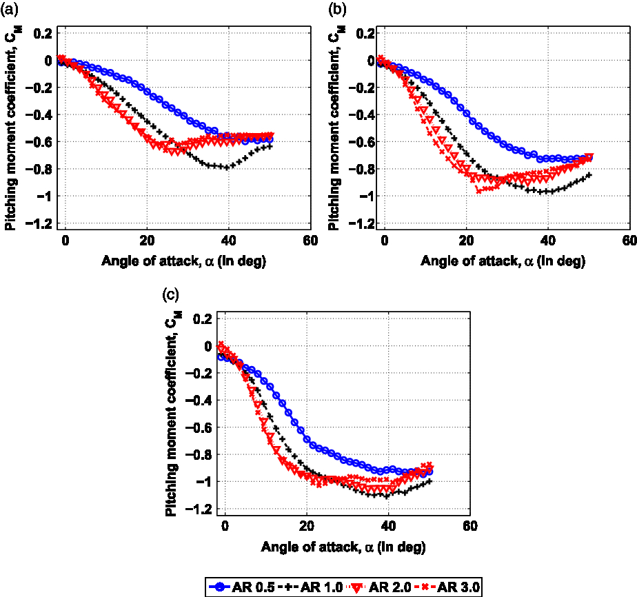
The geometry being analysed is a fin alone configuration, and hence the results related to pitching moment coefficient ( $C_M$
) would govern the hinge moment requirement for the particular variant. Hence, grid fins with higher magnitude of
 $C_M$
(more negative) or slope of the
 $C_M$
versus
 $\alpha$
curve (
 $C_{M_\alpha}$
) would indicate a higher actuator force to retain a particular pitch angle (
 $\alpha$
). These factors emphasise the need to carry out geometry optimisation considering
 $C_M$
as one of the key factors. Present section deciphers the impact of AR variation on grid fin aerodynamics by analysing the variation of
 $C_M$
about leading edges of the middle member at the midspan location (Fig. 14). The accompanying
 $C_M$
curve slope which has been notated as
 $C_{M_\alpha}$
and presented in Fig. 15, has been calculated by first carrying out second-degree polynomial curve fitting to the data of
 $C_M$
versus
 $\alpha$
up to
 $5^{\circ}$
followed by evaluating the value of polynomial’s first derivative with respect to
 $\alpha$
at
 $\alpha=0^{\circ}$
.
Variation of pitching moment coefficient with angle-of-attack for different ARs across grid fins of different g/c (a)  $\text{g/c = 0.3}$
(b)
 $\text{g/c = 0.5}$
(c)
 $\text{g/c = 0.7}$
.

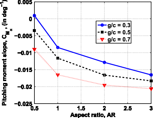
Variation of pitching moment curve slope with AR for different g/c.

Figures 14(a), 14(b), and 14(c) distinctively demonstrate approximately zero pitching moment at small  $\alpha$
for all the g/c and AR variants. As
 $\alpha$
increases,
 $C_M$
value starts becoming negative, and hence presents a negative slope for all the AR variants across all g/c cases. The pertinent slope becomes more negative as g/c increases leading to further enhancement in the negative value of
 $C_M$
. This increase in steepness can be attributed to the elevated
 $C_L$
(Fig. 9(a)) and
 $C_D$
(Fig. 9(b)) for higher g/c. While comparing the AR plots, it can be seen that,
 $C_{M_\alpha}$
for
 $AR=2.0$
and 3.0, undergoes steeper reduction in their values up to moderate angles (ranging between
 $\alpha=26^{\circ}$
to
 $28^{\circ}$
). This underlines the enhanced stability of high AR grid fins leading to a higher hinge moment requirement. This can again be attributed to the higher lift for high AR fins at these angles as established earlier in Fig. 10. Thus, AR and g/c increment would lead to elevated hinge moment requirements, leading to increased actuator weight liabilities. It can also be discerned that, high AR fins undergo a steeper and earlier drop in stability due to their hastened stalling characteristics. For instance,
 $C_M$
curve slope starts becoming positive at around
 $\alpha=26^{\circ}$
to
 $28^{\circ}$
for
 $AR=2.0$
and 3.0, whereas it is found to occur between
 $\alpha=39.5^{\circ}$
to
 $44^{\circ}$
in the case of
 $AR=0.5$
and 1.0 grid fins.
Figures 14(a), 14(b), and 14(c) show the most gradual drop in  $C_M$
for
 $AR=0.5$
followed by
 $AR=1.0$
. This gradual drop can be associated with its lower lift. Moreover, the gradual transition of
 $AR=0.5$
towards positive slope present between
 $\alpha=39.5^{\circ}$
to
 $44^{\circ}$
can be explained to be caused due to its gradual stalling characteristic discussed earlier. The effect of increased flow separation for higher AR can be linked to the increase in
 $C_M$
increment steepness for
 $AR=1.0$
.
The increased variation between the low AR grid fin’s aerodynamic characteristics compared to the reduced deviation amongst the high AR grid fins can be deciphered through these plots also. Thus,  $C_{M_\alpha}$
undergoes significant reduction between
 $AR=0.5$
and
 $AR=1.0$
(Fig. 15) whereas, the reduction is significantly lower between
 $AR=2.0$
, and 3.0. Moreover, qualitative deviation between low AR grid fins is significantly higher whereas, they are similar for the high AR grid fins. Similar to
 $C_L$
and
 $C_D$
plots, deviation between the high AR grid fins and
 $AR=1.0$
plots reduced as g/c increased in the case of
 $C_M$
plots also.
This section efficiently deliberates the factors to be considered while selecting the final AR to alleviate hinge moment requirements.
3.2.5 Resultant aerodynamic force coefficient (drag polar)
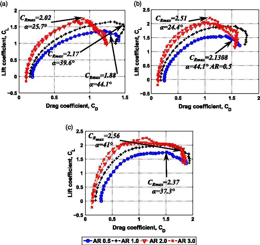
Drag polar reflects the aerodynamic information necessary for the performance analysis of an aerodynamic body. It is a relationship between the lift and drag forces generated by an aerodynamic body (Fig. 16).
Polar curves for different AR across grid fins of different g/c (a)  $\text{g/c = 0.3}$
(b)
 $\text{g/c = 0.5}$
(c)
 $\text{g/c = 0.7}$
.

As seen in Fig. 16, the aerodynamics associated with the high AR fins are similar, whereas the low AR fins present a considerable disparity for all g/c. Plot pertaining to  $AR=0.5$
is closer to the horizontal axis due to its lower lift and drag characteristics for most angles. Maximum
 $C_L$
occurs at a lower
 $C_D$
value for higher AR indicating improved performance. Moreover, the apparent steeper drop in value of
 $C_L$
for
 $AR=2.0$
and 3.0 indicate their reduced manoeuvrability. The resultant aerodynamic force (
 $C_R$
) can be evaluated by using the formula
 $\sqrt{C_L^2+C_D^2}$
, and is graphically represented on a drag polar by distance of the polar drag points from the origin. The occurrence of an earlier
 $C_{Rmax}$
(maximum resultant aerodynamic force) for higher AR and a delayed one for lower AR are due to the stall characteristics as discussed earlier. At higher g/c (Fig 16(b) and 16(c)), it can be noted that
 $C_{Rmax}$
increases even further as AR increases for grid fins due to the lift and drag elevation. Similar to the aforementioned trends, difference between
 $AR=1.0$
and the high AR grid fins reduce as g/c increases.
3.2.6 Aerodynamic efficiency (
${\textbf{C}}_{\textbf{L}}/{\textbf{C}}_{\textbf{D}}$
)

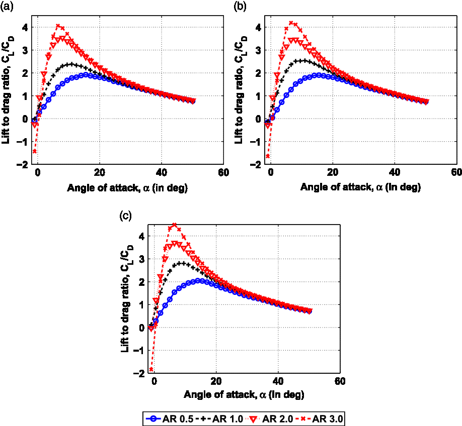
Figure 17, presents a tangible gain in aerodynamic efficiency with increased AR for all g/c variants especially between  $\alpha=0^{\circ}$
to
 $25^{\circ}$
, which resides in the most operable
 $\alpha$
region. Every AR increment for a specific g/c leads to an average efficiency enhancement of 5% compared to the previous smaller AR variant, or an average increment (for all g/c and
 $AR=1.0$
, 2.0, 3.0) of 24% in comparison to
 $AR=0.5$
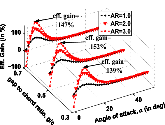
. In-fact Fig. 18 displays an efficiency increment of the order of 140% at
 $\alpha$
close to
 $10^{\circ}$
in the case of
 $AR=3.0$
compared to
 $AR=0.5$
. This further reaffirms the efficiency enhancement characteristic for higher AR in the case of grid fins. The apparent increase in efficiency as AR increases can be associated with the increase in lift within the particular
 $\alpha$
region owing to the increased circulation lift for higher AR. Consequently, since drag is comparable for all the variants, higher AR leads to increased aerodynamic efficiency. Interestingly, efficiency converges for all the variants at higher angles (
 $\alpha>22^{\circ}$
). Thus, AR variation leads to a minimal impact on the efficiency at higher angles. Hence, alleviation of the depreciated efficiency for grid fins in the most operable
 $\alpha$
region, compared to conventional planar fins while retaining the high
 $\alpha$
performance can be obtained by carrying out optimal gap and AR selection. However, AR enhancement also leads to a steeper drop in efficiency with respect to
 $\alpha$
. This factor also has to be considered while selecting the final AR value depending on the operational angle region of the application.
Variation of aerodynamic efficiency with angle-of-attack for different ARs across grid fins of different g/c (a)  $\text{g/c = 0.3}$
(b)
 $\text{g/c = 0.5}$
(c)
 $\text{g/c = 0.7}$
.

Aerodynamic efficiency gain for higher AR compared to  $\text{AR = 0.5}$
at different angles of attack for different g/c.

In order to emphasise the efficiency enhancement achieved through AR increment, Fig. 18, plots the calculated efficiency gain for  $AR=1.0$
, 2.0 and 3.0 across all angles in comparison to
 $AR=0.5$
. The same has been plotted for
 $g/c=0.3$
, 0.5, and 0.7. In this plot,
 $x-axis$
,
 $y-axis$
, and
 $z-axis$
correspond to
 $\alpha$
, g/c, and percentage gain in efficiency values, respectively. Figure 18 clearly demonstrates appreciable enhancement in
 $C_L/C_D$
by increasing AR for all angles. This plot reinstates the enhancement to be maximum in the most operable
 $\alpha$
region (
 $\alpha=5^{\circ}$
to
 $20^{\circ}$
). For instance, the increment is of the order 150% for
 $AR=3.0$
compared to
 $AR=0.5$
in the case of
 $g/c=0.5$
.
Earlier analysis pertaining to the effect of g/c variation on  $C_L/C_D$
(Fig. 9(c)) displayed meagre variation between the different g/c grid fins. However, it is significantly higher when AR is the varying parameter. This is the most important factor while co-relating the impact of g/c and AR on the pertinent
 $C_L/C_D$
. Hence, AR has a more prominent impact on the overall aerodynamic efficiency of grid fins in comparison to g/c. Span selection should be critically analysed while carrying out grid fin designing to achieve enhanced aerodynamic performance especially in the most operable
 $\alpha$
region.
3.3 Span effect: grid fins
Based on thorough comparison of  $C_L$
,
 $\alpha_{max}$
, and
 $C_D$
values pertaining to different grid fin variants, three noteworthy inferences were drawn out.
1. Variation related to higher
$\alpha_{max}$
for lower AR is similar to the deviation occurring between the different AR planar fins(Reference Gabriel and Mueller54). However, contrary to the planar fin trends
$C_{L_{max}}$
is lower for lower AR grid fins.2. Increased aerodynamic deviations between the low AR grid fins in comparison to the one occurring between the high AR grid fins.
3. The deviations related to differences between high AR grid fins and low AR grid fins are mitigated for higher g/c.


These variations are indicative of an underlying phenomena related to span (AR) variation of grid fins. Current section postulates the understanding with respect to this effect called the span effect while considering the inferences drawn out for similar analysis pertaining to planar fins(Reference Gabriel and Mueller54–Reference Mizoguchi and Itoh56). However, the authors suggest further research using flow visualisation tools as well as different grid fin embodiment to corroborate these assertions.
Comparison of  $C_L$
plots in Fig. 10 demonstrated the increase in lift at lower angles for higher AR. This further lead to the advancement of
 $C_{L_{max}}$
for higher AR. This occurs due to the presence of increased cascade effect (lift favourable) area as well increased potential lift due to the higher AR. Figure 13 presented a gradual increment of
 $C_D$
with increasing
 $\alpha$
for
 $AR=0.5$
in all g/c cases. This indicated the reduced flow separation characteristic of grid fins with lower AR. Hence, the delayed stall for lower AR as established earlier in Fig. 11(c). It has been established by the authors(Reference Tripathi, Misra and Sucheendran52) that, flow separation linked to the topmost and lowermost members governed the
 $\alpha_{max}$
of cascade type grid fins. The delayed stall characteristic of lower AR for these fins indicate lowered flow separation on the surfaces thereof for lower AR. The effect responsible for these deviations, has been termed as span effect in this section (paper). However, due to the lack of visualisation tools, physical reasoning behind this phenomena could not be established during this work.
Interestingly, the trend associated with increased aerodynamic deviation between the low AR grid fins compared to the deviation between the high AR grid fins is similar to the trend observed by numerous authors for monoplane wings(Reference Gabriel and Mueller54–Reference Mizoguchi and Itoh56). For monoplane wings this deviation as well as the reduced  $\alpha_{max}$
for low AR wings were asserted to be due to the presence of wing-tip vortices escaping to the upper surfaces leading to flow re-energization. Hence, the delayed stall as well as increased deviation between the low AR wings. The similarity of these two factors with the grid fins (in the current paper) indicate the presence of a similar phenomena for grid fins. However, this needs further deliberation to underscore and acquire visual insight in to the actual flow-physics. It is also noteworthy that, this effect is more prominent at high
 $\alpha_s$
leading to increased deviation between the aerodynamic characteristics at high
 $\alpha$
. This accounts for the increased deviation between the different AR fins at higher angles in Fig. 10(a) for
 $g/c=0.3$
.
Throughout Figs 10, 13, and 14, it was apparent that, differences between the low AR and high AR fins reduced as g/c increased. This indicates the reduction of span effect for higher g/c. Thus, the advantages associated with increased  $\alpha_{max}$
and flatter post-stall drop in lift for lower AR alleviates after a certain g/c. Hence, beyond a certain g/c, AR increment within that specific g/c would lead to meagre advancement of the lift alongside reduced
 $\alpha_{max}$
. This establishes bounded g/c expansion for increased lift associated with higher AR. Moreover, the reduced aerodynamic deviation between high AR variants establish reduced span effect influence at higher AR. Thus, span effect reduces for higher g/c as well as higher AR.
Span effect which encompasses the aforementioned aerodynamic trends is a phenomena leading to improved control characteristics for such control surfaces. The influence of this effect due to AR reduction increases as  $\alpha$
increases, or g/c reduces. As noted earlier, the underlying flow-physics needs to be further analysed through flow field visualisation tools. Moreover, further analysis by increasing the number for planar members would lead to increased understanding with respect to this effect.
4.0 CONCLUSION
The study carried out in this paper pertains to a sequence of wind tunnel experiments performed to understand the effects of aspect ratio (AR) variation through span alterations on the subsonic aerodynamics of “cascade” type grid fin configuration. These experiments were performed for several gap-to-chord ratio (g/c) cases with gap as the varying parameter and a constant chord. Herein, gap corresponded to the gap between the planar lifting members of the grid fins. Some prominent inferences derived from this analysis were:
1. Increased AR leads to lift enhancement and an appreciable aerodynamic efficiency enhancement especially in the most operable angle-of-attack region pertinent to control surfaces.
2. Efficiency enhancement for higher AR was achieved at the expense of reduced stall angle and a steeper post-stall drop in lift. Thus, flow separation is seemingly higher for higher AR. This was corroborated by the presence of steeper drag increment with angle-of-attack for higher AR at low angles of attack.
3. Pitching moment stability posed an additional limitation towards AR enhancement due to its increased (negative) value for higher AR. Thus, a higher span would present additional hinge moment requirements, and hence increased actuator weight liabilities.
4. The enhanced impact of AR on lift, drag, aerodynamic efficiency and pitching moment characteristics of grid fins suggested the need to critically analyse this parameter while carrying out grid fin geometry optimisation.
5. Qualitative differences between the low AR fins (
$AR<2$
) related to lift, drag, and stall angle were significantly higher compared to those existing between the high AR fins (
$AR\geq 2$
). Hence, the aerodynamics related to these different AR regime fins displayed significant disparity.6. These variations indicated the presence of an underlying effect called the span effect, which lead to delayed stall angle for lower AR. The influence of this effect was more pronounced at higher angles of attack and for lower g/c.
7. This study will be helpful for a grid fin designer to optimally select g/c and AR parameters based on pre-determined stall angle, maximum lift and aerodynamic efficiency requirements, along with the permissible hinge moment constraints.
8. Further research using flow-field visualisation tools can be carried out to establish comprehensive in-sight into the underlying flow-physics related to span effect. Moreover, comparison of the same parameter for grid fins with different number of planar members can lead to greater understanding of the effects thereof.


ACKNOWLEDGEMENTS
The authors would like to thank the Department of Aerospace Engineering situated at the Defence Institute of Advanced Technology (DIAT), who provided us the necessary funds to carry out the experiments. We would like to convey our deepest gratitude to Lt. Col. S. Kartik Raja SC, who helped us in acquiring the necessary results for our analysis during his post-graduate dissertation project at DIAT. We would also like to thank the staff of MART facility located at CSIR-NAL, Bangalore, who provided regular insight and expertise that greatly assisted in performing the experiments.