


1. Introduction
The purpose of this paper is to investigate what change the Comninou–Dundurs effect (C-D effect) may produce on subglacial lakes and on sliding conditions at the base of an ice sheet or glacier in regions where the basal ice rests on basal till. the C-D effect equations (Reference DundursDundurs, 1967, Reference Dundurs1969; Reference ComninouComninou, 1977,Reference Comninou1978; Reference Comninou and DundursComninou and Dundurs, 1980) essentially were developed for smeared-out glide- and climb-edge dislocations on an interface between elastic solids of differing elastic constants. the C-D effect may be important to some basal processes of ice sheets and glaciers. Appendix A gives a simple physical explanation of its origin. (In another geophysical area, a generalization of the C-D effect under dynamic conditions provides an explanation for the existence of fast-moving localized packets of smeared glide-edge dislocations (slip pulses) that move on earthquake faults, and an explanation for the apparent lack of frictional heating on the San Andreas Fault, CA, U.S.A. (reviewed in Reference Ben-ZionBen-Zion, 2001; Reference Ranjith and RiceRanjith and Rice, 2001).)
Subglacial lakes (water lenses) whose horizontal dimensions are large compared with their depth can be considered to be cracks. They are subjected to basal shear loading if they are situated anywhere except under an ice dome. If the average slope of the upper ice surface is not zero, a shear traction stress is exerted at the base of an ice sheet. No shear traction stress, however, can be placed across an effective water-lens crack where the water depth is appreciable. the shear traction is concentrated, therefore, in the regions at the crack tips where the water depth is very small. In this paper the subglacial lake is treated as a crack loaded in shear. (For simplicity, only two-dimensional mode II shear cracks in plane strain are considered in this paper.)
In the case of an elastic solid, the solution of a shear crack that lies parallel to the x axis can be generated from the stress–strain-displacement field of a glide-edge dislocation of Burgers vector bx in the x direction (Reference WeertmanWeertman, 1996). (The dislocations dealt with in this paper are not dislocations of atomic dimensions but mathematically defined dislocations in an elastic continuum that can have any macroscopic scale (see Reference WeertmanWeertman, 1996).) the traction shear stress σxy for a dislocation situated at the origin is equal to

where G is the shear modulus and σ =1–ν, where ν is Poisson’s ratio. the shear stress arising from a distribution Bx(x) of glide-edge dislocations smeared out on the slip plane is therefore
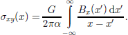
The shear crack solution found for Equation (2) is (Reference WeertmanWeertman, 1996)

and

where σA is the applied shear stress and Dx(x) is the net displacement in the horizontal direction (x direction) at x across the crack faces. Equations (3) and (4) are valid for –a ≤ x ≤ a, where a is the half-length of the crack. (Bx = Dx = 0 for | x |> a.)
No normal (tensile or compressive) traction stress σyy is produced at the slip plane (or crack plane) by a discrete glide-edge dislocation or a smeared dislocation distribution Bx(x) of glide-edge dislocations. to have a normal stress on the crack plane produced by dislocations requires a distribution By(x) of climb-edge dislocations whose Burgers vectors are in the vertical direction (y direction). Equations (1–4) apply for climb-edge dislocations if σxy is replaced with σyy, bx with by, Bx(x) with By(x), and Dx(x) with Dy(x).
2. Comninou–Dundurs Equations
Equations (1–4) must be modified if a shear crack (or a tensile crack) exists on an interface separating elastic half-spaces A and B (with solid A above and solid B below) whose elastic constants differ. A glide-edge dislocation of Burgers vector bx situated at the origin at the interface produces the following long-range (inverse distance dependence) and short-range (exists only where the dislocation exists) traction stresses across the interface


A climb-edge dislocation of Burgers vector by produces the traction stresses


In these equations δ(x) is the Dirac delta function δ (→ ∞ when x → 0, and δ = 60 when x ≠ 0) and β is the Dundurs parameter defined as (Reference DundursDundurs, 1967, Reference Dundurs1969)

The effective shear modulus and the effective alpha term are (Reference WeertmanWeertman,1996)

In the equations above, σA =1–νA and σB =1–νB, where νA and νB are Poisson’s ratio of solid A and solid B, and GA and GB are the shear moduli of solids A and B. (See appendix C inReference WeertmanWeertman,1996 for a derivation of these equations.)
Just as Equation (2) above arose from Equation (1), Equations (5) and (6) for the interface traction stress of discrete dislocations lead to the following equations for the traction stress across the interface for a smeared-out distribution Bx(x) of glide-edge dislocations and a smeared-out distribution By(x) of climb-edge dislocations.

Equations (9) are the Comninou–Dundurs equations. They give the shear traction stress σxy and the normal traction stress σyy across an interface (with solid A above and solid B below) that arise from a smeared-out distribution Bx(x) of glide-edge dislocations and a smeared-out distribution By(x) of climb-edge dislocations. the inverse Comninou–Dundurs equations
are (after a sign correction is made inReference WeertmanWeertman,1996)

The non-traction stress σxx at the interface is given by

where the upper sign is used above the interface and the lower sign below it. (This equation can be obtained from the p. 452 equations in appendix C ofReference WeertmanWeertman,1996. See also p. 50–51 of the same work.) Thus

where σxx+ is the value of σxx above the interface, and σxx– is the value below it. Similarly, the rotation pseudo-stress σω on either side of the interface is given by

and

The rotation pseudo-stress is defined by  where ω is the elastic rotation.
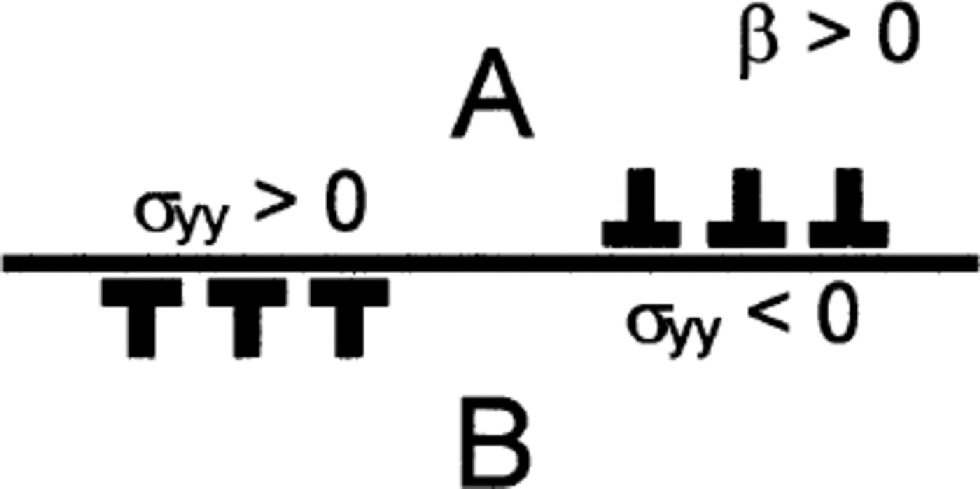
Note in Equation (9) that when β ≠ 0 a distribution of glide-edge dislocations Bx(x) gives rise not only to a shear traction stress on the slip plane but also to a normal traction stress. the normal traction stress exists only where the dislocations are present. Figure 1 (for β > 0) indicates that glide-edge dislocations of opposite sign produce normal stress of opposite sign. the Dundurs parameter β is equal to zero if  If the two solids are incompressible then
 and β = 0. Note that if the upper half-space is incompressible and the lower is not, the Dundurs parameter β is always positive. (If GA = GB,
 and
 then

Dislocations of opposite sign on interface between half-spaces A and B when β >0, showing regions of compressive (negative) normal stress σyy where Bx>0 and of tensile (positive) normal stress σyy where Bx<0. (Curvature of interface is ignored.)
2.1. Solution of Comninou–Dundurs equations for shear crack
Let a positive shear stress σA (such as is applied at the base of an ice sheet if the ice thickness is larger on the left side, or
negative x side, of the crack than on the right side, or positive x side) be applied to a crack. the solution of the Comninou– Dundurs equations gives the displacements at the crack faces for an interface mode II shear crack, with no shear or tensile traction stress acting on the crack faces. the solution is


if interpenetration of the crack faces is allowed. Here Dx is the net displacement across the crack faces in the horizontal direction (x) and Dy is the net displacement in the vertical direction (y). (See p.393–395 inReference WeertmanWeertman,1996 and note that these pages gives the solution for the mode I rather than the mode II crack. the solution of the mode II crack is the same as for the mode I crack if the displacements Dx and Dy are interchanged and one sign is reversed.) In Equation (13), a is the half-length of the crack (–a ≤ x ≤ a); σA is the applied shear stress, γ0 – cosh ηπ and η = (1/π)arctanh β . (For  and γ0 ≈1.02.) the crack center is at x = y = 0. Note in Equation (13) the weird Williams oscillations (Reference WilliamsWilliams, 1959) of ever-decreasing spacing as a crack tip is approached. Oscillations cease where a – | x |>
2a exp(–π/2η). for  a – |x|> 5.37610–11a. the Williams oscillations die out at very small distances from a crack tip and can be ignored. In the Equation (13) solution the crack faces are traction-free because the short-range traction stresses arising from the C-D effect are canceled by the long-range stresses of glide- and climb-edge dislocation distributions. (The climb- and glide-edge dislocation distributions are found from Equation (13) using the relationships Bx = –dDx/dx and By = –dDy/dx:)
Figure 2a and b show plots of normalized displacements  and
 andnormalized dislocation distributions
 and
 vs normalized distance x/a from the center of the crack found from Equation (13) for the case of
 and a positive applied shear stress σA. the curves are cut off before the anomalous Williams oscillations appear. (The displacement Dx and edge-glide dislocation density distribution Bx is similar to that of a Griffith–Inglis mode II crack. the displacement Dy and edge-climb dislocation density distribution By has the type of symmetry of a Zener–Stroh–Koehler mode I crack (Reference WeertmanWeertman,1996) but differs from it because the net Burgers vector of climb dislocations is zero rather than of finite amount. the crack is mixed-mode I and II in character.) Note that on the right side Dy is negative. If interpenetration of the crack faces is not allowed, at the right side the crack faces make contact over an extended area. the more complicated solution of Equation (9) is required in this situation. If the Dundurs constant β = 0 then Dy = 0 and Dx has the value of a Griffith–Inglis mode II crack.
(a) Normalized plot of displacement Dx and Dy vs x/a from Equation (8) for the case of (b)Normalized plot of dislocation density components Bx = –dDx/δx and By = –dDy/dx vs x/a.
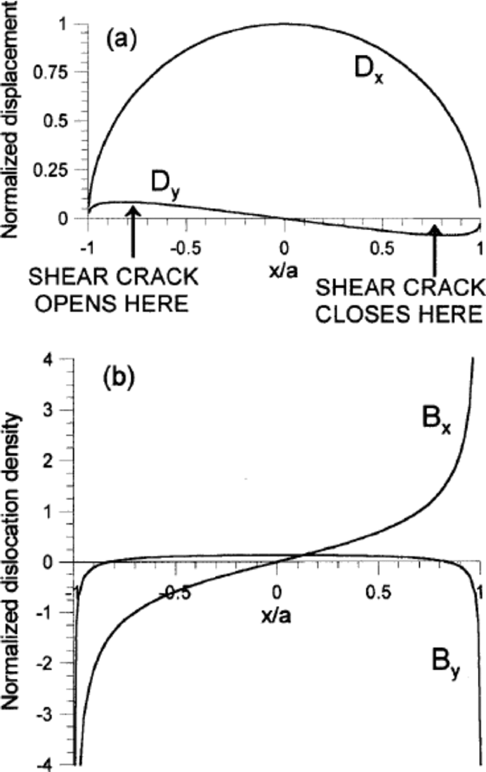
It is seen in Figure 2b that the glide-edge dislocation distribution Bx is very large near the tips of the crack. the existence of these dislocations gives rise to large compressive stress to the right of the righthand tip, and to large tensile stress to the left of the lefthand tip. the stress from these dislocations opens the left tip and closes the right tip. Figure 3 shows schematically the glide-edge dislocations that might exist near the tips of a water-lens shear crack at the base of an ice sheet subjected to a positive shear stress σA.
Anomalous C-D effect pressure regions at ice–till contact with thick, lake-like water lens. the contact zone is subjected to an overall shear stress.

3. Application to Base of An Ice Mass
The Comninou–Dundurs equations apply at an interface between elastic solids. for non-elastic solids it is reasonable to expect a similar (generalized) C-D effect to exist because the C-D effect arises from the difficulty, shown schematically in Figure 6 in Appendix A, of fitting together two half-spaces of different material whose interface in any region is subjected to non-uniform slip, and at least one of the half-spaces contains a compressible solid.
At the base of an ice sheet or a glacier the interface is between basal ice (solid A or ice of Fig. 1 and 3), which deforms by high (homologous) temperature creep, and the bed (solid B or till of Fig. 1 and 3), which may be elastic if it is bedrock and non-elastic if it is made of glacial till. High-temperature creep deformation of ice is incompressible (provided that no voids appear at grain boundaries during creep and trapped air bubbles have negligible volume). If the ice sheet or glacier bed is elastic bedrock the β parameter can be expected to be insignificant. Note that the shear modulus of rock is at least an order of magnitude greater than that of cold ice. Thus, using Equation (7) for a rough measure of an effective Dundurs parameter, β is small and can be ignored. the C-D effect, therefore, should be unimportant when basal ice rests on bedrock (or on bedrock veneered with only a thin till layer).
Suppose an ice mass rests on a thick till layer. Reference Tulaczyk, Kamb and Engelhardt.Tulaczyk and others (2000) showed that till, taken from under Whillans Ice Stream (formerly Ice Stream B), Antarctica, is compressible. Thus a generalized Dundurs parameter β is positive. It is prudent, therefore, to consider the C-D effect when basal ice rests on till. Consider a water lens within basal till, shown schematically in Figure 3, whose horizontal dimension is large compared with its thickness. Assume the water thickness is so large that a shear stress cannot be transmitted across the lens because bed irregularities do not penetrate the water layer and make contact with the overlying ice. However, an overall shear stress exists across the base of the ice mass as indicated in Figure 3. (A shear stress of sense given in this figure is produced at the base of an ice sheet if the ice thickness decreases from left to right.) the water lens acts a mode II-type shear crack.
(If the horizontal dimension of the water lens is very much greater than the thickness of an ice sheet the upper ice surface will be horizontal. In this situation no shear stress will be transmitted to the base of the ice sheet over most of the area of the ice lens. In the regions at the edges of the ice lens, however, a shear stress will exist because the upper ice surface no longer is horizontal there. the edge regions of the water lens act as edge shear cracks.)
If the elastic solids of the half-spaces are replaced with non-elastic solids the qualitative behavior of the crack will not change. the mode II shear crack faces should still try to open up on one side (the left side of Fig. 2b and 3) and try to interpenetrate on the opposite side (the right side of Fig. 2b and 3). If the right side of a water lens closes and the left side opens, the crack may shift its position towards the left. This is shown schematically in Figure 4a and b. (If only the left side shifts, the water lens becomes longer in the horizontal direction, as indicated schematically in Figure 4c.)
(a) Same as Figure 3. (b) Water lens moved to the left through opening of left-side low-pressure region and closing of right-side high-pressure region. (c) Water-lens left boundary moved to the left through opening of left-side low-pressure region but with right boundary stationary. (Ice thickness increases towards the left.)

In Tulaczyk and others (Reference Tulaczyk, Kamb and Engelhardt.2000, fig. 4) are shown stress– strain curves of till obtained in triaxial tests. These stress– strain curves approximate well those of an elastic perfectly plastic solid. Reference Tulaczyk, Kamb and Engelhardt.Tulaczyk and others (2000) find that the shear stress at failure is proportional to an effective normal stress. (Reference Alley, Maltman, Hubbardand and HambreyAlley (2000) discusses the uncertainties in our understanding of the rheological properties of till present beneath ice sheets.) the deformation of ice itself can be modeled as that of an elastic perfectly plastic solid. As is well known, early (and reasonable) estimates of ice sheet and glacier profiles were made using this ice rheology.
Assume now, for the purpose of investigating the influence of the C-D effect at an ice-sheet base, that reasonable qualitative results can be obtained by considering both ice and till to be elastic perfectly plastic solids. Assume ice to be incompressible and till to be compressible. the Dundurs parameter β is positive. for simplicity, assume the yield stress σ0 of ice and in situ basal till to be the same. If the yield stress of till is very much greater than the effective one for ice, for all practical purposes, basal ice rests on bedrock and the C-D effect almost entirely disappears. But if the yield stress of till is very much greater than that of ice, the generally accepted concept of deformable soft till glacier beds, based on field observations, is untenable.
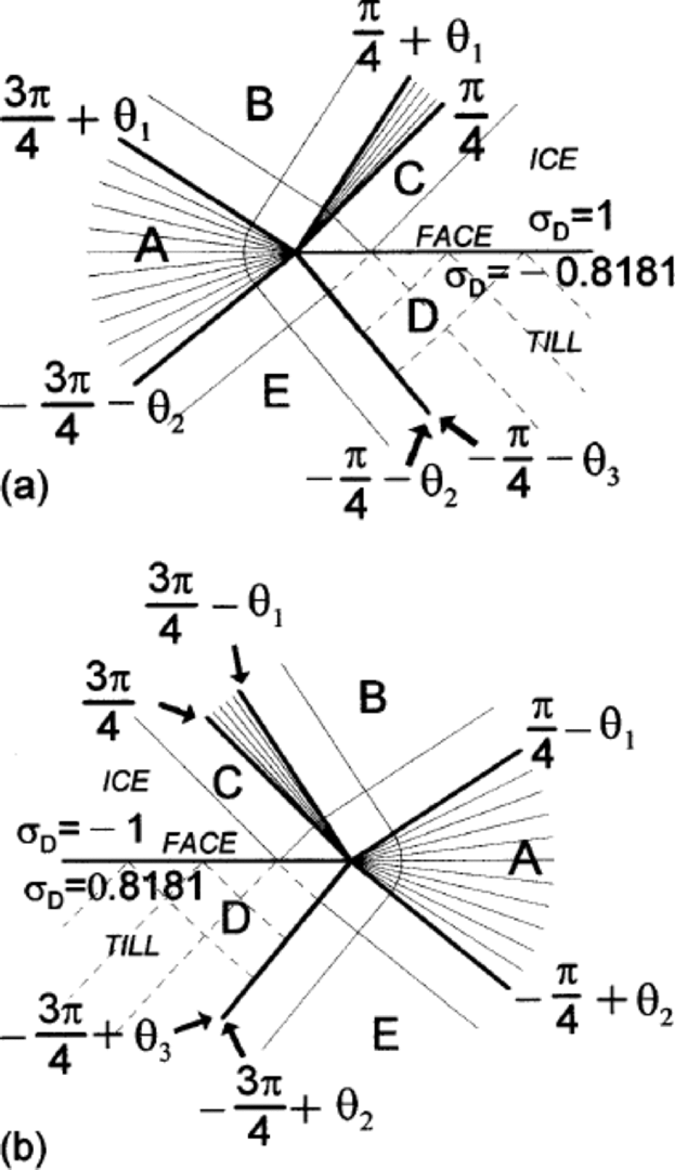
Figure 5a and b show, by means of trajectories across which the shear stress is a maximum, the stress solution near the lefthand tip (Fig. 5a) and the righthand tip (Fig. 5b). the crack tip is at the point where the fan-sector trajectories converge. the crack face is indicated in the figure. the stress solution consists of fan-type sectors and block-type sectors. In each sector the effective stress magnitude is at the yield stress, except in the sector with dashed trajectories. Plastic deformation takes place in the fan sectors. Equations for the stress field in each sector are given in Appendix B. Because of the asymmetry in Figure 5a and b, plastic deformation leads to the closing of the crack faces at the righthand tip and to the opening at the lefthand tip.
(a) Stress-field maximum shear stress trajectories in basal ice and till at left side of water lens when there is a C-D effect. Rheology of ice and till is approximated as an elastic perfectly plastic solid of yield stress σ0. (σD is expressed in units of σ0.) (b) Same as (a) but for right side of water lens.
It is difficult to make a good estimate of just how fast a water lens might migrate. A more refined analysis than the one presented here is required. Avery rough and unreliable estimate can be made using Figure 2a. This figure shows that the vertical elastic displacements are about an order of magnitude smaller than the horizontal elastic displacements for a crack in an elastic solid. Hence one might expect for a crack in a solid that deforms by creep that the vertical crack face velocity VV is an order of magnitude smaller than the horizontal velocity VH. the horizontal velocity can be expected to be smaller than the horizontal velocity at the upper ice surface. If the depth of the lake is D, its right side (right side of Fig. 3) would close in a time of about 10D/VH. (The left side can advance by opening the material beyond the lefthand crack tip.) If the half-length a of the water lens is smaller than the ice thickness, the drift velocity could be of the order of or smaller than aVH/10D. (If the water-lens half-length is much larger than the ice thickness, the water lens becomes an edge crack of effective length equal to ice thickness.) the drift velocity could be large (ma–1 to km a–1) until the water lens reaches a region of low upper-ice-surface horizontal velocity.
4. Discussion
Many subglacial lakes with appreciable water volume are now known to exist in Antarctica (Reference Siegert, Dowdeswell, Gorman and McIntyre.Siegert and others, 1996; Reference Dowdeswell and SiegertDowdeswell and Siegert, 1999; Reference SiegertSiegert, 2000a,Reference Siegert, Maltman, Hubbard and Hambreyb). (The first indication of a subglacial lake under an Antarctic ice sheet was found by Reference Robin, de, Swithinbank and MRobin and others (1970).) It is interesting to note that most of the subglacial lakes catalogued by Siegert and others, as they point out, are close to an ice divide. of course, the greater ice thickness at ice divides favors basal meltwater production and lake creation there, but the heat produced by frictional sliding also favors increased basal meltwater production and possible lake formation away from ice divides. the observation that the location of a subglacial lake is biased to be near an ice divide suggests that some mechanism exists that drives a basal water lens to move towards increasing ice thickness. (Of course, the bottom topography at any one location may have large bowl-shaped elevation variation and a large geothermal heat flux that favor a stationary subglacial lake.The analysis of this paper is not applicable to such lakes.)
This paper suggests a mechanism by which crack-shaped basal water lenses situated between basal ice and basal till can shift their positions over time. the mechanism is based on the Comninou–Dundurs equations that are applicable to dislocation distributions on interfaces including those of the special cases of interface cracks. Although the Comninou– Dundurs equations apply to dislocations at interfaces between elastic solids, they should indicate reasonably well the qualitative behavior of interface cracks between non-elastic solids. Thick basal water lens and subglacial lakes essentially are interface cracks subjected to mode II shear crack loading. Because of the C-D effect a mode II shear crack takes on an additional mode I character. At one end of the crack (that nearest an ice divide) a tensile mode I component is added that opens the crack and causes that end to move towards the ice divide. At the other end of the crack (that furthest from an ice divide) a compressive mode I component is added that closes the crack and causes that end also to move towards the ice divide. Hence a water lens could move over time towards an ice divide if not prevented from doing so by large bottom topography variations and by lack of a thick layer of basal till. If subglacial lakes are able to shift their positions over time, it is possible that larger lakes devour smaller ones. (Moreover, the expected high-pressure zone just beyond the downstream side edge of a crack-like lake might impede water flow.) Under Pleistocene ice sheets, subglacial lakes may grow so large and so unstable that they dump and contribute to Heinrich events.
The position and history of subglacial lakes obviously depends on various factors. These include water flux though them, their thermal history, basal melting and freezing of water, and pressure gradients within them. the C-D effect discussed in this paper may be almost as important a factor for some types of subglacial lakes.
Acknowledgement
I thank the anonymous reviewer for perceptive suggestions that have led to a much improved revised version of my paper.
Appendix A
Physical Origin of the Comninou– Dundurs Effect
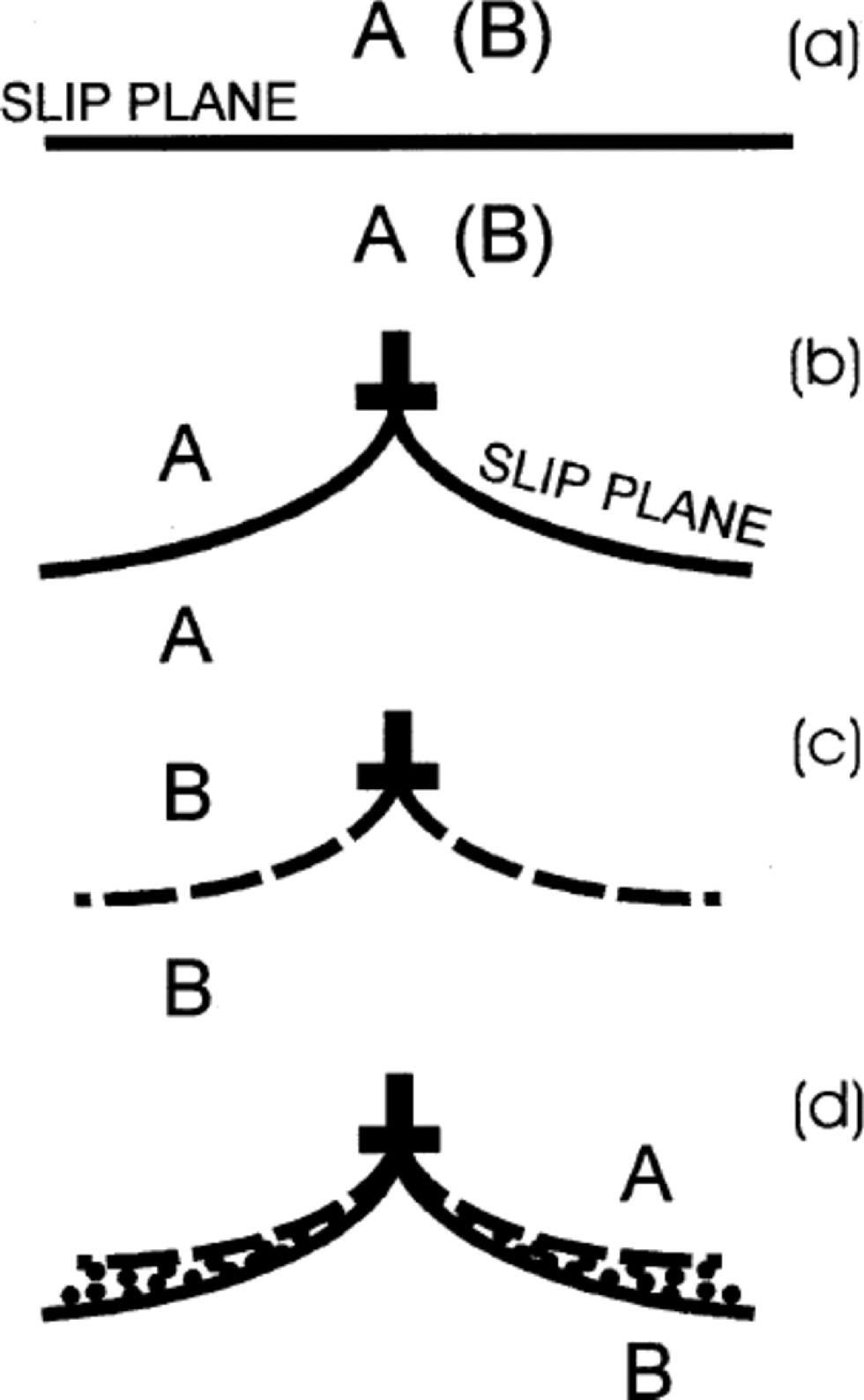
The physical origin of the C-D effect can be understood from Figure 6 and the equation of the displacement field of a glide dislocation of Burgers vector bx:
(a) Slip plane without glide-edge dislocation between two elastic half-spaces A-A or B-B. Elastic constants of half-space A differs from those of half-space B. (b) Glide-edge dislocation on deformed slip plane between half spaces A-A. (c) Same as (b), but A-A half-spaces replaced with half-spaces B-B. (d) Glide-edge dislocation on slip plane between half-space A and half-space B if the deformed slip planes of (b) and (c) were unaltered.

Here u and v are the displacements in the horizontal (x) and vertical (y) directions for a dislocation situated at the origin, and r0 is a constant of order of magnitude of bx.
If the solid is incompressible, its Poisson’s ratio has the value  At the slip plane there is no vertical displacement. However, if the solid is compressible (that is,
 the vertical displacement of the slip plane (y = 0) is logarithmic divergent at the origin. the deformed slip plane is shown schematically in Figure 6. Figure 6a shows the slip plane before an edge dislocation is placed on it in a solid A or in a solid B of differing Poisson’s ratio. Figure 6b and c show schematically the deformed slip plane in solid A or in solid B. Figure 6d shows what would happen if the upper half of the solid A in Figure 6b were to be joined to the bottom half of solid B in Figure 6c and no change occurred in the deformed slip plane of either figure. There would be overlap of material as indicated in the figure (or a gap formed if the top half of B were joined to the bottom half of A in Figure 6b and c). the overlap (or gap) is prevented from occurring by the establishment of a normal traction stress across the interface between two different materials on which resides a glide dislocation. A normal traction stress does not exist at the slip plane of a glide-edge dislocation in a solid whose elastic constants are the same everywhere. Its appearance here is the C-D effect.
Actually, the Figure 6 explanation, although essentially correct in outline, is too simple and is somewhat misleading. It implies, using Equation (1), that if Poisson’s ratios for the two half-spaces are identical, no normal traction will be set up because the vertical displacements of Figure 6b and c are the same even if the shear moduli of the two half-spaces are different. However, if the moduli are different, the displacements will differ, partly because the partition of the total Burgers vector of the glide-edge dislocation between the two half-spaces is different. See appendix C of Reference WeertmanWeertman (1996) for a detailed derivation of the Comninou–Dundurs equations and their inverse. If a climb-edge dislocation is placed on the interface of Figure 6, a shear traction stress is set up. A climb-edge dislocation is one whose Burgers vector is perpendicular to the interface.
Appendix B
Asymptotic Stress Field At Crack Tip
Figure 5a and b show what would be the stress field (under plane strain conditions) within the ice and till near the left-side and the near right-side crack tips of the Figure 3 shear crack if ice were incompressible but till were not and their rheology is that of elastic perfectly plastic solids with the same elastic constants (G = GA = GB). Figure 5 shows the maximum shear stress trajectories. (These trajectories are a generalization of those of the Hutchinson (Reference Hutchinson1968a,Reference Hutchinsonb) mode II crack-tip field solution of a shear crack in a homogeneous solid.)
Assume the crack faces near a crack tip are traction-free (other than the traction stress arising from the overburden pressure). Because of the term  in Equation (11a), the deviatoric stress at the crack faces near a tip (that is,
 can only equal the yield stress just above the crack face and not below it. Thus at the right-side crack-face tip

and at the left side

On both sides ice above the crack faces is at the yield stress, and till below the faces is below the yield stress. the stress fields in the different sectors are (when  and
 given below.
The stress components in the sectors in Figure 5b are (with –π ≤ θ ≤ π and

The traction stress at a crack face is zero. the rotation pseudo-stress is zero in a sector unless an explicit expression for σω is given. (The need for a log singular rotation pseudo-stress in sector D is explained in Weertman (Reference Weertman1996, in press).) the constants are given by

The value of θ3 is found from the conditions that at  S = and σ0, and at
 The angles θ1 and θ2 are determined once the constant σP0 is specified, provided they are positive quantities. the angles given above are for the physically possible most negative value of σP0. the most negative value of σP0 is chosen because in Figure 3b, which is the elastic-case analogue, a large compressive stress is expected ahead of the right-side crack tip. (The most positive value, σP0 = 0.570796σ0, requires θ1 = 0, θ2 =17.6208˚. for σP0 = 0:
The stress components in the sectors in Figure 5a are (with –π ≤ θ ≤ π and 

The deviatoric stresses at the crack faces given by Equation (B2) and the stress fields of Figure 5 imply in Figure 3 that the ice face will creep downwards at the right-side crack tip until ice makes contact with till. At the left side the ice face creeps away from the till face opening the crack. the left side has a mode I tensile component that can lead to crack growth towards the left.
(Reference Sham, Li and HancockSham and others (1999) have analyzed interface crack-tip fields in elastic perfectly plastic solids where the yield stress is not the same on either side of the interface.)



