1. Introduction
The transition from sitting to standing is an essential activity in our daily lives; however, this poses significant challenges for elderly individuals who suffer from muscle degeneration in their lower limbs. With the increasing prevalence of ageing societies [Reference Lin and Cui1], there is a growing need to explore the mechanisms that assist elderly people in standing. This assistive mechanism can not only help elderly individuals engage in physical activity, like healthy individuals, but can also prevent complications related to the lower limbs. The act of standing relies on the coordinated movement of the hip, knee, and ankle joints in the lower limbs. Among these, the knee joint plays a crucial weight-bearing role, making it a primary consideration in the design of assistive devices.
Researchers have proposed various approaches to assist with standing. Chuy et al. [Reference Chuy, Hirata, Wang and Kosuge2] introduced a method that involves providing support for the upper limbs to assist individuals in standing. Kim et al. [Reference Kim, Song, Suh, Lee and Kang3] developed a technique inspired by how nurses assist people in standing. This technique involves pushing against the back and buttocks diagonally to facilitate standing. Hou et al. [Reference Hou, Chen, Chen, Li and Li4] developed a brain-machine interaction for a single-degree-of-freedom sit-to-stand transfer robot. By introducing a novel electroencephalogram decoding algorithm, they successfully provided active assistance to users during the transition from sitting to standing. Hiyama et al. [Reference Hiyama, Kato and Inoue5] focused on providing the necessary force for standing by applying power to push against the hips and thighs while the individual is seated.
Some researchers hope to help elderly people stand by using exoskeletons. An exoskeleton is a type of wearable robot designed to augment human motor functions and enhance human strength [Reference Bettella, Tortora, Menegatti, Petrone and Felice6, Reference Arefeen and Xiang7]. By wearing an exoskeleton, elderly people can achieve normal standing functions. Consequently, there has been an increasing focus on the study of auxiliary standing exoskeletons [Reference Eguchi, Kadone and Suzuki8–Reference Huo, Mohammed, Amirat and Kong12]. The design of exoskeleton structures is primarily based on the degree of freedom of human joints [Reference Nesler, Thomas, Divekar, Rouse and Gregg13, Reference Zhou, Chen, Chen, Bai, Zhang and Wang14]. Since the knee joint plays a crucial role in weight-bearing during the standing process, it must exist and serve as an active degree of freedom. Kimura et al. [Reference Kimura, Pham, Kawanishi and Narikiyo15] designed an exoskeleton comprising hip, knee, and ankle joints; it reduced the exertion on the participants’ legs while they were standing. Additionally, Choi et al. [Reference Choi, Lee, Kang and Young16] employed a bilateral knee exoskeleton to investigate the relationship between maximum biomechanical benefits and assistance strategies. Chen et al. [Reference Chen, Zhong, Ma, Guan, Qin, Chan, Law, Qin and Liao17] proposed a trajectory online modification algorithm for exoskeletons with active hip and knee joints to stabilise the system balance during standing.
Exoskeletons typically employ series elastic actuators to achieve compliant driving and reduce the output impedance. Shepherd et al. [Reference Shepherd and Rouse18, Reference Shepherd and Rouse19] designed an exoskeleton incorporating a series of elastic actuators. The series elastic actuator uses a unique transmission configuration with a series fibreglass beam spring that improves torque control and reduces the output impedance. Kamali et al. [Reference Kamali, Akbari and Akbarzadeh20] designed an exoskeleton for assisting in standing. The exoskeleton is driven by a series elastic actuator and provides low output impedance, enabling more accurate and robust human–robot interaction force control. Moreover, by using sample trajectory databases and initial joint angles to predict the user’s sit-to-stand trajectory, the exoskeleton achieves precise assistance.
With further research, it has been recognised that the constant stiffness of series elastic actuators cannot fully meet the demands of human–robot interactions. During standing, the torque and stiffness of human joints change continuously [Reference Pfeifer, Vallery, Hardegger, Riener and Perreault21]. If the joint stiffness of an exoskeleton can be adjusted in real time depending on human motion states, the compliance of human–robot interactions, wearing comfort, and motion adaptability can be significantly enhanced [Reference Sun, Guo, Sun, He and Xiao22, Reference Li, Chen, Zhang, Li, Wang, Fang and Yang23]. Therefore, researchers have developed various variable stiffness actuators and have successfully applied them to exoskeletons. Zhu et al. [Reference Zhu, Wu, Chen, Zhang and Wu24–Reference Zhu, Wu, Chen, Xu and Shao26] proposed a variable stiffness actuator that can adjust the joint stiffness by changing the spring preload via the wire rope. Furthermore, the joint stiffness range can be reconfigured by changing the windings of the wire rope. This actuator was integrated into the knee joint, enabling stiffness modulation. Liu et al. [Reference Liu, Hong, Penzlin, Misgeld, Ngo, Bergmann and Leonhardt27] designed a variable stiffness actuator that adjusts joint stiffness by altering the elasticity of the leaf springs and implemented it in the knee joint. Its effectiveness was demonstrated in sit-to-stand transition tasks. Zhou et al. [Reference Zhou, Shao, Di, Feng, Ding and Zhang28] designed a variable stiffness actuator based on a guide-bar mechanism for the lower limb exoskeleton, which enables stiffness adjustment with low energy consumption.
This paper presents a novel auxiliary standing knee exoskeleton with variable stiffness designed for individuals with lower limb weakness. The device can dynamically adjust the stiffness of the knee joint in real time according to different motion states during the standing process. The proposed knee joint employs a parallel dual-path hybrid actuation mechanism for stiffness variation. The two motors independently adjust the two parallel elastic actuators to regulate the joint’s output torque and stiffness. Both actuators generate torque in the same direction. Mechanical analysis of the exoskeleton system has been conducted to determine its achievable torque output range and stiffness adjustment range. Compared with conventional designs, the exoskeleton system proposed in this study demonstrates the following innovations:
(1) A novel parallel dual-path hybrid actuation mechanism for a variable stiffness knee joint is proposed. Unlike conventional variable stiffness joints in which two motors operate independently, with one motor solely responsible for torque output and the other exclusively for stiffness adjustment, the design in this study employs two functionally coupled motors, each driving an elastic actuator. Both actuators are connected to the knee joint in parallel, and they contribute simultaneously to torque generation and stiffness modulation, albeit with distinct emphasis. The two motors can provide power simultaneously, making the joint’s output torque equal to the sum of their individual outputs, thereby significantly enhancing the joint’s torque output capability.
(2) This paper proposes a multidimensional comprehensive performance evaluation method for the variable stiffness knee exoskeleton. The effectiveness of the exoskeleton was systematically validated through experiments focusing on four aspects: mechanism stiffness, tracking performance, wearing assistance effect, and human comfort. The experimental results indicate that the actual stiffness of the exoskeleton aligns with the theoretical value, and it exhibits favourable trajectory tracking accuracy across various stiffness configurations. During practical wearing trials, the exoskeleton effectively reduced the knee joint torque required during human standing. Furthermore, the study revealed that lower stiffness settings provide a better subjective comfort experience. Using this performance evaluation method, the effectiveness of the exoskeleton was demonstrated.
The remainder of the paper is organised as follows: Section 2 describes the design of the structure of the knee exoskeleton. Based on the structure, the output torque and stiffness of the knee joint are analysed. In Section 3, experiments are conducted to evaluate the proposed variable stiffness knee joint. The experiments focus on assessing the stiffness characteristics, trajectory tracking capabilities, actual auxiliary function, and influence of joint stiffness on human comfort. Section 4 concludes the work of the whole article and introduces future work.
2. Mechanical design and analysis
2.1. Principle of variable stiffness of the knee joint
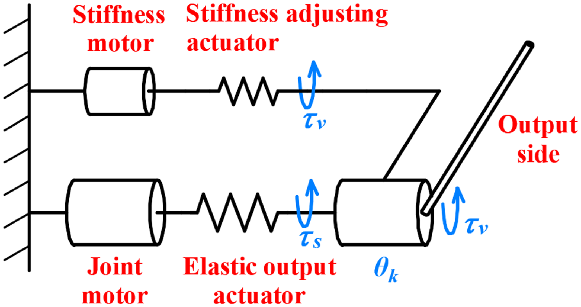
To assist elderly individuals with insufficient lower limb strength in standing up and to accommodate the diverse movement states of the human body during the standing process, this study developed a variable stiffness knee exoskeleton. The proposed knee exoskeleton employs two motors to cooperatively control a joint. By adjusting the position and extension of springs at both ends of the joint, the system achieves precise control over joint displacement and stiffness; it can also be equivalent to controlling the output torque and stiffness by regulating two elastic structures with two motors.
Schematic diagram of the variable stiffness mechanism.

A schematic diagram of the variable stiffness knee joint is shown in Figure 1. One motor, referred to as the joint motor, is primarily responsible for generating joint torque and is connected in series with an elastic output actuator. The other motor, known as the stiffness motor, is linked to a stiffness-adjusting actuator that enables a wide range of stiffness adjustments. The torque and stiffness of the joint are realised by the cooperation of two motors. The joint motor carries the main output torque. Its output torque is transmitted through the elastic output actuator connected in series. The stiffness of the elastic output actuator slightly changes with variations in motor torque, but it has little effect on the overall stiffness. The stiffness motor adjusts the overall stiffness by manipulating the position and length of the spring of the stiffness-adjusting actuator, and it also generates a certain external output torque. The output torque is transmitted through the stiffness-adjusting actuator; however, its output torque is much less than that of the joint motor, and it does not bear the primary output force. This design distinguishes the functions of the two motors, with each primarily responsible for one function: torque output or stiffness adjustment. The advantage is the reduction in control complexity while allowing for more targeted motor selection, thus enhancing the power utilisation efficiency of each motor. Both motors can provide torque to the joint. This structural configuration enhances the system’s fault tolerance. In the event of a single motor failure, the other motor remains operational, ensuring system safety. Additionally, the stiffness adjustment motor does not need to counteract the load generated by the joint output motor, enabling faster and more agile stiffness regulation.
The output torque of the knee joint
 $\tau _{k}$
is the sum of the output torques of both the actuators and can be mathematically expressed as follows:
 \begin{equation} \tau _{k}=\tau _{s}+\tau _{v} \end{equation}
where
 $\tau _{s}$
is the output torque of the elastic output actuator.
 $\tau _{v}$
is the output torque of the stiffness-adjusting actuator. The following equation can then be derived:
 \begin{equation} K_{k}=\frac {\partial {\tau _{k}}}{\partial {\theta _{k}}}=\frac {\partial ({\tau _{s}+\tau _{v}})}{\partial {\theta _{k}}}= \frac {\partial {\tau _{s}}}{\partial {\theta _{k}}}+\frac {\partial {\tau _{v}}}{\partial {\theta _{k}}}= K_{s}+K_{v} \end{equation}
where
 $K_{k}$
is the stiffness of the knee joint.
 $K_{s}$
is the stiffness of the elastic output actuator.
 $K_{v}$
is the stiffness of the stiffness-adjusting actuator. According to this equation, the stiffness of the knee joint is equal to the sum of the stiffness of the two actuators. Therefore, both the overall torque and stiffness of the knee joint are co-determined by the two elastic actuators.
2.2. Design of the elastic output actuator
The elastic output actuator should be designed according to the structural requirements. It should have the ability to transmit the entire torque generated by the joint motor. The required torque output of the joint motor is 30 Nm, which corresponds to approximately 25
 $\%$
of the torque needed for the knee joint during standing. The elastic output actuator transforms the rigid drive of the joint motor into a compliant drive through internal elastic elements. The elastic element adopts a spring, making the size and elastic coefficient easier to control. The whole structure adopts a ring structure, which transforms the linear motion of the spring into the whole rotary motion. When assisting individuals in standing, the joint motor is subjected only to the torque generated by gravity, which hinders the person from standing. As a result, the spring remains either in compression or tension throughout this process. Even if there is a discrepancy between the ideal rotation angle of the motor and the actual rotation angle of the knee joint, only the length of the spring is affected without altering the compression or tension state. Therefore, the elastic output actuator alone must be designed as a unidirectional output mechanism.
(a) Structure of the elastic output actuator. (b) Principle of the elastic output actuator.

The overall structure and principle of the elastic output actuator are illustrated in Figure 2(a) and (b). The actuator primarily consists of a coaxial rotating input part, an output part, and four compression springs compressed between them. In the schematic diagram of the principle, only the relative motion of the input part and the output part is considered. Therefore, the output part can be regarded as a fixed end. The motor torque is initially transmitted to the input part, which rotates counterclockwise and compresses the spring. The torque is subsequently output through the output part. The elastic output actuator can be simplified into four basic units that are uniformly arranged in a ring shape and completely consistent.
The basic unit is analysed mechanically. First, the force of each spring in the elastic output actuator is calculated as follows:
 \begin{equation} F_{s}=k_{m}(l_{s0}-l_{s1}) \end{equation}
where
 $F_{s}$
is the compression force of a single spring.
 $k_{m}$
is the stiffness coefficient of the spring.
 $l_{s0}$
is the original length of the spring.
 $l_{s1}$
is the actual length of the spring after compression. The torque of the elastic output actuator is the sum of the four basic units and can be expressed as follows:
 \begin{equation} \tau _{s}=4F_{s}R_{s}\cos {\frac {\theta _{s0}-\theta _{s1}}{2}} \end{equation}
where
 $\tau _{s}$
is the torque transmitted by the elastic output actuator.
 $R_{s}$
is the distance from the centerline of the compression component of the spring to the rotation centre.
 $\theta _{s0}$
is the initial included angle between the input part and the output part.
 $\theta _{s1}$
is the change in the angle produced by the compression process. Then, the stiffness of the elastic output actuator
 $K_{s}$
can be calculated as follows:
 \begin{equation} K_{s}=\frac {\partial \tau _{s}}{\partial \theta _{s1}} \end{equation}
The torque and stiffness curves of the elastic output actuator are illustrated in Figure 3. The torque transmitted by the actuator increases as the compression angle increases, with a maximum value of 32 Nm. It is sufficient to meet the torque requirements of the joint motors. Additionally, the stiffness variation of the actuator is relatively small, fluctuating within a range of 9 Nm/rad. The elastic output actuator is characterised by a wide range of torque variations and a small range of stiffness variations; this allows the joint motor to fully utilise its high output performance without greatly affecting the overall stiffness.
(a) Elastic output actuator torque curve. (b) Elastic output actuator stiffness curve.

2.3. Design of the stiffness-adjusting actuator
This section focuses on the design of the stiffness-adjusting actuator, which primarily adjusts the joint stiffness. The stiffness-adjusting actuator modifies the overall stiffness by manipulating the position and length of the spring. The structure and schematic diagram of the designed mechanism are shown in Figure 4(a) and Figure 4(b), respectively. The stiffness-adjusting actuator surrounds the joint motor, thereby reducing the axial size. After being driven by a gear reduction ratio of 4, the stiffness motor connects to the compression spring. The gear transmission structure not only enhances the torque for stiffness adjustment but also facilitates the structural layout. To minimise the impact of friction, a linear bearing is incorporated into the compression structure of the spring.
(a) Structure of the stiffness-adjusting actuator. 1 is the joint motor, 2 is the rotating plate, 3 is the coupling shaft, 4 is the near gear bearing, 5 is the inclined support block, 6 is the compression spring, 7 is the linear bearing, 8 is the spring support bar, 9 is the bearing connector, 10 is the far gear bearing, 11 is the stiffness motor, 12 is the driven gear, 13 is the collar, and 14 is the drive gear. (b) Schematic diagram of the stiffness-adjusting actuator.

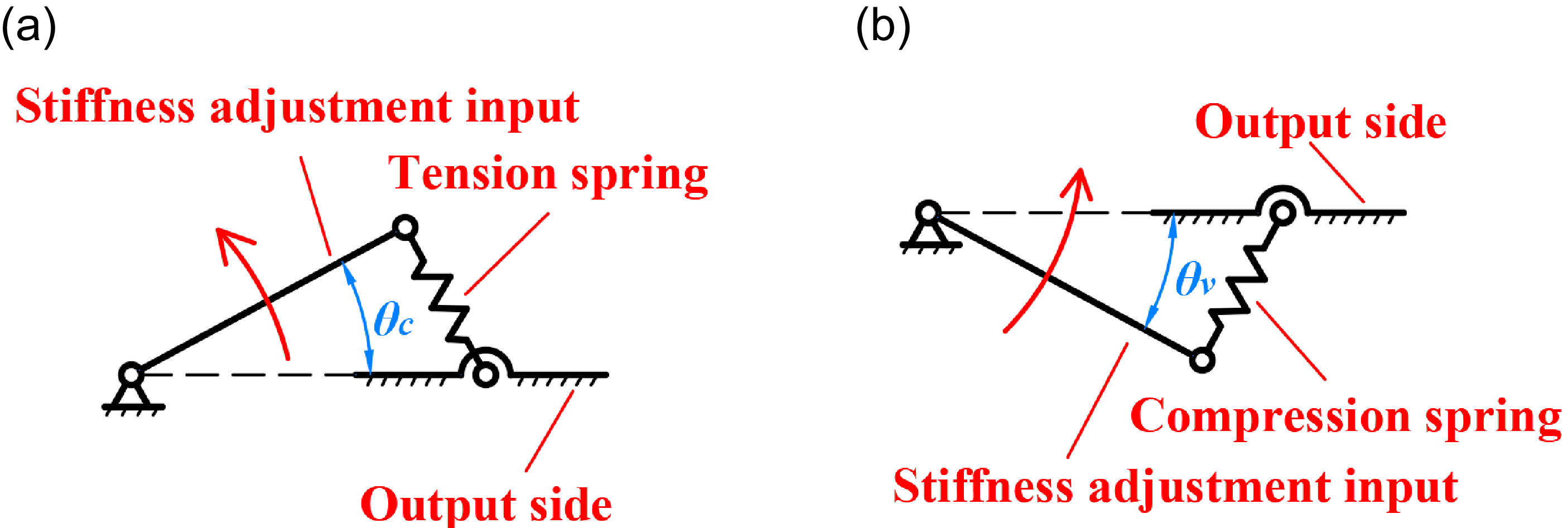
Compared with a tension spring, a compression spring is preferred because it requires less structural strength when the stiffness is adjusted within the same range. A schematic diagram of the tension spring mechanism is presented in Figure 5(a). Only the relative motion between the input side and the output side is considered in the analysis. Therefore, the output side can be regarded as a fixed end.
 $\theta _c$
is the included angle between the stiffness adjustment input and output side in the tension spring mechanism. When
 $\theta _c$
is set to 0, the structure reaches a balanced position where the spring’s influence on stiffness is negligible. As
 $\theta _c$
increases progressively, tension builds up within the spring, generating a torque that leads to a continuous increase in joint stiffness. While this method achieves the goal of stiffness adjustment, it necessitates an increase in spring tension and a thicker structural design to ensure strength as the stiffness increases. In contrast, the compression spring mechanism depicted in Figure 5(b) features two equilibrium positions.
 $\theta _v$
is the included angle between the stiffness adjustment input and output side in the compression spring mechanism. With
 $\theta _v$
set to 0, the compression spring exerts no force on the rotating shaft arm and generates no torque. When
 $\theta _v$
reaches its maximum value, corresponding to the original length of the compression spring, the spring does not exert force or generate torque. These two equilibrium positions contribute to a torque distribution wherein the torque is smaller on the sides and larger in the middle. During the stiffness adjustment process, arbitrary torque values are employed twice. Consequently, a wider range of stiffness can be achieved when the same torque change is used.
Simplified diagrams of the two variable stiffness mechanisms. (a) Schematic diagram of the tension spring mechanism. (b) Schematic diagram of the compression spring mechanism.

The stiffness-adjusting actuator is analysed mechanically. The length
 $l_{v3}$
of the compression spring can be expressed as follows:
 \begin{equation} l_{v3}=\sqrt {l_{v1}^2+l_{v2}^2-2l_{v1}l_{v2}\cos ({\theta _{v0}-\theta _{v1}})} \end{equation}
where
 $l_{v1}$
is the distance from the rotating shaft to the fixed position of the compression spring at the output end.
 $l_{v2}$
is the distance from the rotating shaft to the fixed position of the compression spring at the rigidity adjustment input end.
 $\theta _{v0}$
is the initial included angle between the input and output.
 $\theta _{v1}$
is the change angle of the input end. The angle
 $\theta _{v2}$
between the spring and the output end is as follows:
 \begin{equation} \theta _{v2}=\arccos {\frac {l_{v1}^2+l_{v3}^2-l_{v2}^2}{2l_{v1}l_{v3}}} \end{equation}
The output torque
 $\tau _v$
of the stiffness-adjusting actuator is as follows:
 \begin{equation} \tau _v=k_n(l_{v0}-l_{v3})l_{v1}\sin {\theta _{v2}} \end{equation}
where
 $k_n$
is the stiffness of the compression spring.
 $l_{v0}$
is the original length of the compression spring. The stiffness
 $K_{v}$
of the mechanism is as follows:
 \begin{equation} K_{v}=\frac {\partial {\tau _v}}{\partial {\theta _{v1}}} \end{equation}
The torque and stiffness curves of the stiffness-adjusting actuator are shown in Figure 6. The torque in the compression spring mechanism has a shape with a prominent middle peak and zero values on both sides. This is due to the presence of two equilibrium positions in the mechanism. As the torque gradually increases, the stiffness becomes positive, while it becomes negative when the torque gradually decreases. Overall, the stiffness tends to decrease monotonically. During the stiffness adjustment process, each torque value is employed twice, resulting in a multiplication effect on the stiffness range and expanding the stiffness adjustment range for torques with the same peak value. Thus, within the same range of stiffness adjustment, the required peak torque can be reduced, which in turn reduces the power source and strength demand for stiffness adjustment.
(a) Torque curve of the stiffness-adjusting actuator. (b) Stiffness curve of the stiffness-adjusting actuator.

2.4. Overall analysis of the knee joint
By substituting Equations (4) and (8) into Equation (1), the relationship between the output torque
 $\tau _{k}$
of the knee joint and the angular variation
 $\theta _{s1}$
of the elastic output actuator and the angular variation
 $\theta _{v1}$
of the input end of the stiffness-adjusting actuator can be obtained (see Figure 7). The knee joint provides an output torque range of 0 to 38 Nm. The direction in which the stiffness motor applies force is aligned with the standing direction of humans. As a result, the torque of the entire knee joint is greater than the joint torque alone.
The relationships among
 $\tau _{k}$
,
 $\theta _{s1}$
, and
 $\theta _{v1}$
.

To achieve a balance between high load-bearing capacity and low self-weight, the exoskeleton system incorporates integrated considerations in both material selection and structural design. For materials, aluminium alloy and carbon fibre composites are primarily adopted to simultaneously meet performance, weight, and cost requirements. For structural design, through finite element simulation and computational analysis, a refined design of critical components has been implemented to realise a unification of lightweight construction and high structural strength.
By substituting Equations (5) and (9) into Equation (2), the relationships between the stiffness
 $K_{k}$
of the knee joint and
 $\theta _{s1}$
and
 $\theta _{v1}$
can be obtained, as shown in Figure 8 . The adjustment range of stiffness for variable stiffness joints is −19 to 324 Nm/rad. As depicted in the figure, the stiffness adjustment depends primarily on the stiffness-adjusting actuator, whereas the angle change of the elastic output actuator has little influence on the overall stiffness.
The relationship between
 $K_{k}$
,
 $\theta _{s1}$
, and
 $\theta _{v1}$
.

3. Experiment and evaluation
To evaluate the practical performance of the exoskeleton, this study proposes a multidimensional comprehensive performance evaluation method. The effectiveness of the exoskeleton was validated through experiments focusing on four aspects: mechanism stiffness, tracking performance, wearing assistance effect, and human comfort. The first experiment focused on stiffness identification, aiming to verify whether the design stiffness change aligns with the theoretical analysis. The second experiment involved trajectory tracking under dynamic conditions, with the objective of evaluating the joint performance in accurately following predefined trajectories. The third experiment aimed to validate the assistive performance of the exoskeleton. By comparing the muscle forces of the lower limbs with and without exoskeleton assistance, the study assessed whether the exoskeleton provided assistance. The fourth experiment investigates the impact of varying stiffness on human comfort. By comparing the subjective experiences of individuals assisted by exoskeletons with different stiffness levels, whether the change in the joint stiffness of the exoskeleton affects the comfort of the human body can be evaluated.
Experiments were carried out on the proposed variable stiffness knee joint. The joint motor is an AK80-64 motor (CubeMars, China). It has a high output torque of 48 Nm, satisfying the requirements. The stiffness motor employed is the M3508 motor (DJI, China), which can deliver a continuous maximum torque of 3 Nm. The structure of the real knee joint is shown in Figure 9. Its mass is 3.7 kg.
The structure of the real knee joint.

3.1. Stiffness identification experiment
In the proposed variable stiffness mechanism, both the elastic output actuator and the stiffness-adjusting actuator affect the stiffness of the knee joint. By conducting stiffness identification on these two mechanisms separately, the consistency of the actual stiffness of the knee joint with the theoretical value can be determined.
The two experimental setups used for measuring the stiffness are shown in Figure 10. The key distinction between the two setups lies in the fact that when the stiffness of the elastic output actuator is measured, the spring component of the stiffness-adjusting actuator is removed, leaving only the elasticity of the elastic output actuator intact. Conversely, when the stiffness of the stiffness-adjusting actuator is measured, the spring of the elastic output actuator is eliminated, retaining solely the elasticity of the stiffness-adjusting actuator. During the experiment, one end of the joint is fixed while the motor rotates it to various angles, and the readings from the tension meter at the opposite end are recorded. By obtaining readings from multiple angles, the torque variation can be determined. The stiffness can be calculated subsequently using Eqs. (5) and (9).
Experimental platform for stiffness identification. (a) Stiffness measuring platform of the elastic output actuator. (b) The stiffness measuring platform of the stiffness-adjusting actuator.

The compression angle of the elastic output actuator ranges from 0 to 0.197 rad. In the experiment, the spring is initially compressed by a certain angle. Further, the motor is controlled to rotate multiple times, with each rotation being 0.035 rad. After each rotation, the corresponding reading from the tension meter is recorded, and the average stiffness within the angular variation range is calculated. Owing to the small angular interval, this average stiffness can be regarded as the stiffness value corresponding to the midpoint of the interval. By connecting the stiffness values at different angles into a curve, the actual stiffness data of the elastic output actuator obtained in the experiment can be visualised. Since the stiffness value obtained in the experiment corresponds to the midpoint of the angular variation interval, the stiffness at the edges of the actuator’s motion range cannot be calculated.
After each rotation, the corresponding readings of the tension meter are recorded, and the average stiffness value for the range of angle change is calculated. Since the change in angle is small each time, the average stiffness can be considered as the stiffness at the median angle within that angle range.
The stiffness values at various angles are connected to form a curve, which represents the actual stiffness of the elastic output actuator obtained from the experiment.
A comparison between the experimental results and the theoretical values is presented in Figure 11. The trends align well, with a maximum deviation of less than 4 Nm/rad. Since the stiffness range of this actuator varies from 154 to 163 Nm/rad, the corresponding maximum relative error is only 2.6
 $\%$
. This error is minor and falls within an acceptable range. Therefore, it can be concluded that the stiffness of the elastic output actuator agrees with the theoretical stiffness and that the difference between the two results has a negligible effect on the behaviour of the system. This discrepancy may arise from differences between the actual stiffness of the compression spring and its theoretical value. Additionally, the difference in compression degrees at different positions due to non-parallel ends of the compression spring can also lead to deviations in the spring force compared with the theoretical value.
Comparison between the experimental values and theoretical values of the elastic output actuator.

The stiffness-adjusting actuator has a compression angle range of 0 to 0.140 rad. The method for measuring its actual stiffness is essentially the same as that for measuring the elastic output actuator. Each time, the input end is deflected by 0.035 rad. The average stiffness for this angular interval is calculated based on the readings from the tension meter and is considered as the stiffness value of the midpoint of the interval. By connecting the stiffness values at different angles into a curve, the actual stiffness of the stiffness-adjusting actuator can be obtained. For the same reason as the elastic output actuator, the stiffness at the edges of its motion range cannot be calculated either.
A comparison between the experimental results and theoretical values is shown in Figure 12. The trend is similar, with a maximum deviation of less than 10 Nm/rad. Thus, it can be concluded that the stiffness change of the mechanism is close to the theoretical value. This discrepancy may arise from a certain gap between the stiffness of the compression spring and its theoretical value. Additionally, some gaps may exist during the machining process.
Comparison between experimental values and theoretical values of the stiffness-adjusting actuator.

Eq. (2) indicates that the overall stiffness of the knee joint can be obtained by summing the stiffness of the two mechanisms. Based on the experimental results, the actual stiffness of both structures is like their respective theoretical values. Thus, it is deduced that the overall stiffness of the knee joint is consistent with the theoretical value.
3.2. Trajectory tracking experiment
The tracking performance of joints plays a crucial role in their ability to perform tasks effectively. However, the variation in stiffness of the knee joint can significantly affect its tracking performance. Consequently, tests and comparisons of the tracking performance of the knee joint under different stiffness conditions are essential.
A platform designed for conducting tracking performance experiments on a variable stiffness joint is shown in Figure 13. The platform secures one end of the joint while allowing the other end to move as instructed. The two motors are output through the elastic output actuator and the stiffness-adjusting actuator. After the encoder and the output of the joint are coaxially fixed, the actual output angle of the joint motors after passing through the flexible structure can be accurately measured. In the experiment, a load is added to the output end of the joint. The weight of the load is approximately 3 kg.
Trajectory tracking experimental platform.

Experimental results of trajectory tracking. (a) Trajectory tracking angle curve. (b) Trajectory tracking error curve.

The experiment involves dividing the stiffness of the knee joint into three levels: high, moderate, and low. The tracking performance of the knee joint is then compared under these different stiffness conditions. The high stiffness level is set to 300 Nm/rad, the moderate stiffness level is set to 150 Nm/rad, and the low stiffness level is set to 50 Nm/rad. In the experiments, the knee joint angle during a subject’s standing is adopted as the ideal trajectory. The joint motor follows this ideal trajectory, whereas the stiffness motor designs the motion trajectory by considering both the transmission ratio and the stiffness required for the experiment.
The trajectory tracking angle curve is shown in Figure 14(a), while the error curve is shown in Figure 14 (b). Under all three stiffness conditions, the tracking performance of the knee joint is good, with the maximum error not exceeding 0.04 rad. The majority of the error is concentrated in the intermediate stage; this is because during this stage, there is a rapid change in angle, leading to a noticeable lag in tracking. A comparison of the tracking deviations under the three stiffness conditions was conducted using the following formula:
 \begin{equation} {S_e}=\sqrt {\frac {1}{n-1}\sum _{i=1}^{n}{e_i}^2} \end{equation}
where
 $S_e$
is the degree of deviation of the actual trajectory from the theoretical trajectory. The larger
 $S_e$
is, the greater the tracking error. e is the error angle at a certain moment, while n is the number of sampling moments. Sampling is conducted every 0.05 s. The calculation results are shown in Figure 15. The error is the smallest at high stiffness and the largest at low stiffness. A lower joint stiffness results in greater flexibility, which can improve safety and comfort. However, this will also lead to greater tracking errors.
Tracking deviation of trajectory.

3.3. Exoskeleton assistive effect experiment
For the exoskeleton designed in this study, it is necessary to verify its assistive effect by examining the changes in the muscle force of the lower limbs when the human is standing while wearing the exoskeleton. The common method used to assess the variation in muscle force involves measuring electromyographic (EMG) signals. This method can be used to represent the degree of muscle force exertion. Therefore, in this experiment, the EMG signals of the lower limbs with and without exoskeleton assistance were compared to determine the ability of the system to assist in standing.
Owing to the primary focus of this research being on the innovative design of the structure, only a single-leg exoskeleton was processed and assembled for verification purposes. The exoskeleton interfaces with the human body through wide encircling straps attached at the thigh and calf. The inner surface of the straps is lined with highly elastic foam. This design achieves large-area surface contact between the human and the exoskeleton, effectively dispersing forces and torques over the leg; this ensures that the wearer perceives only mild skin compression without significant discomfort. During the experiments, the exoskeleton was equipped with an ankle joint. Together with the knee joint, it formed a continuous force-transmission chain that directed most of the gravitational force to the ground. This configuration not only reduced the load on the wearer but also mitigated the imbalance induced by the weight of the exoskeleton. The ankle joint is not powered. To prevent the movement of the ankle joint from affecting the experiment, it remained completely fixed during the experimental process. Some electronic components are fixed to the calf of the exoskeleton. The exoskeleton-wearing condition is shown in Figure 16. The overall mass of the exoskeleton is 4.4 kg after adding the ankle joint.
Exoskeleton wearing condition.

Ten 24
 $\pm$
3-year-old subjects were included in this study. All of them signed written informed consent forms. They all had good leg conditions and were capable of independent standing. The exoskeleton was adjusted to ensure alignment between the human and exoskeleton knee joints, as well as consistency in their movement directions, prior to each subject’s experiment. This can avoid forces and torques resulting from kinematic mismatch. Additionally, all the volunteers received training on how to use the exoskeleton. The exoskeleton operates under an open-loop control scheme. Its motion is controlled to replicate the knee joint angle observed during standing, albeit at half the angular velocity of typical human movement. The trajectory is smooth with gradual acceleration and deceleration, effectively avoiding impact forces or torques caused by abrupt motion. Throughout the motion of the exoskeleton, its stiffness remains at 230 Nm/rad. During the experiments, two EMG sensors (DataLITE Wireless EMG Amplifier LE230; Biometrics Ltd., UK) were placed on the surface of the subjects’ legs to measure the EMG signals of the relevant muscles, as shown in Figure 17. The measured muscles included the vastus medialis and vastus lateralis. They are closely related to the standing movement of the knee joint.
Position of the EMG sensors.

With the assistance of the exoskeleton, the subject can realise the posture transition from sitting to standing. The subject’s process from sitting to standing is shown in Figure 18. The sequence of movement is shown from (a) to (f).
Process from sitting to standing.

During the experiment, raw EMG signals were collected using sensors. Integrated EMG values can be calculated from these signals as follows:
 \begin{equation} I=\int _ {t_{1}}^{t_{2}}\left |X(t)\right |dt \end{equation}
where
 $I$
is the integrated EMG value.
 $t_{1}$
is the start time.
 $t_{2}$
is the end time.
 $X(t)$
is the EMG signal. Larger integrated EMG values indicate greater muscle force, whereas smaller integrated EMG values indicate lower muscle force. However, the extent of change between them is not entirely consistent.
A comparison of the integrated EMG values of all the subjects with and without exoskeleton assistance revealed that the peak integrated EMG values of both muscles significantly decreased for all the subjects when they were assisted by the exoskeleton. The specific results are illustrated in Figure 19. The horizontal axis indicates the serial number of different subjects, whereas the vertical axis indicates the descending proportion of peak values of each muscle with exoskeleton assistance compared with those without assistance. The range of decrease for the vastus medialis ranged from 38
 $\%$
to 59
 $\%$
, with an average decrease of 50
 $\%$
. For the vastus lateralis, the range of decrease is from 40
 $\%$
to 57
 $\%$
, with an average decrease of 48
 $\%$
. From these results, it can be concluded that the exoskeleton reduces the force of human muscles and provides help for standing.
Proportion of peak EMG signal reduction in different subjects with and without exoskeleton assistance.

The peak reduction proportion of the integrated EMG values varies among all the subjects for several reasons. First, there are individual differences among people, leading to variations in muscle exertion levels. Moreover, during the actual interaction between humans and exoskeletons, the degree of cooperation varies, which can influence the actual assistance provided by the device.
3.4. Effect of exoskeleton stiffness on human comfort
The stiffness of the exoskeleton can influence human comfort. Therefore, in this experiment, the subjects were assisted by exoskeletons with different stiffness levels, and the relationship between exoskeleton stiffness and human comfort was determined based on the participants’ subjective experiences.
Ten 24
 $\pm$
3-year-old subjects participated in this experiment. Apart from stiffness, all the other experimental conditions of the exoskeleton remained the same as those in Section 3.3. The exoskeletons were adjusted to two significantly different stiffness levels, 50 Nm/rad and 300 Nm/rad, allowing the subjects to stand with assistance from each stiffness condition. Experiments under these two stiffnesses can reveal the influence of high stiffness and low stiffness on human comfort. Following the experiment, the subjects evaluated and rated the two stiffness levels depending on their subjective experiences during the assistance process. Ratings were on a scale from 0 to 100, with higher scores indicating greater comfort during the assistance process.
The evaluation of the subjects indicated that stiffness selection is crucial for comfort in exoskeleton use. They all agree that the experience is more comfortable with lower stiffness assistance. This improved comfort is reflected mainly in soft joint movements and smooth initiation. The scoring results in Figure 20 further validate the notion that lower stiffness leads to greater comfort. However, discomfort at higher stiffness levels may stem from excessive impact during assistance or over-constraint of leg movement.
The average scores of participants’ ratings on the comfort level of exoskeletons with different stiffness levels.

Notably, the exoskeleton developed in this study is attached only to one side of the leg. While this design simplifies the structure and makes it easier to wear, it also affects the motion support. This might have an impact on people’s subjective feelings. The asymmetric force transmission may introduce undesired lateral forces and external rotation torques, while the weight tends to cause a sense of imbalance. To mitigate these undesirable mechanical loads, the following measures were implemented: wide encircling straps were used to disperse forces and torques over the leg; motion control was optimised to reduce transverse impact and rotational effects; and the exoskeleton was adjusted to accommodate individual anthropometric variations. Furthermore, a force-transmission chain was constructed to direct the gravitational force to the ground, and a lightweight structural design was adopted to alleviate the imbalance caused by weight. After the implementation of these measures, feedback from all subjects indicated that they did not perceive noticeable undesirable forces, torques, or a sense of imbalance. However, these methods cannot eliminate the effects of unilateral attachment totally. Therefore, addressing this issue will be a key focus of subsequent research. The conclusion section of this paper will further elaborate on the specific research required to resolve this problem in the future.
4. Conclusion
In this study, a novel auxiliary standing knee exoskeleton with variable stiffness was designed to assist elderly individuals with weakened lower limbs in achieving standing ability. The variable stiffness mechanism consists of an elastic output actuator and a stiffness-adjusting actuator. The relationships between the joint stiffness and the angles of the elastic output actuator and the stiffness-adjusting actuator were studied, and a corresponding diagram was produced. The stiffness of the knee joint can be adjusted from −19 Nm/rad to 324 Nm/rad, making it adaptable to different standing states of the human body and increasing the compliance of human–robot interaction.
A comprehensive multidimensional performance evaluation was conducted on the exoskeleton. First, a stiffness identification experiment is performed. The results demonstrate that the actual stiffness of the joint aligns closely with the calculated theoretical value. The dynamic tracking performance of the knee joint is subsequently studied through experiments. The experimental findings indicate that there is a certain lag in joint tracking and that the stiffness of the joint affects the tracking performance. Specifically, when the joint stiffness is lower, the flexibility becomes more pronounced, resulting in a larger error in the tracking process. Further, the practical effectiveness of the exoskeleton was validated. A comparison of the EMG signals with and without exoskeleton assistance demonstrated its auxiliary role in standing. Finally, the influence of exoskeleton joint stiffness on human comfort was determined. It was established that lower stiffness resulted in softer joints and a more comfortable experience for the wearer.
Combining the experimental results from Sections 3.2 and 3.4, it can be observed that exoskeletons exhibit distinct advantages at different stiffness levels: higher stiffness enhances trajectory tracking accuracy, whereas lower stiffness increases human comfort. Therefore, compared with fixed-stiffness exoskeletons, exoskeletons with adjustable stiffness can better adapt to the motion status of the human body, striking a balance between accuracy and comfort. During the initial activation phase, the exoskeleton can employ lower stiffness for a smooth start-up, followed by adjustments as needed. In the main assistance phase, higher stiffness should be used to ensure accurate assistance. As the person is near the completion of standing, the exoskeleton should be adjusted to lower stiffness to reduce constraints on the human body and enhance comfort.
In future studies, efforts should be devoted to addressing the interference caused by the unilateral connection of the exoskeleton on motion support effectiveness. Specific research to be conducted includes, but is not limited to, quantifying the magnitude of disturbance forces and torques, exploring symmetrically designed exoskeletons wrapped around the leg, and further reducing the mass of the exoskeleton. The advancement of these tasks will contribute to enhanced human–robot coordination, preventing physical harm to the wearer and alleviating the wearability burden. In addition to the research on the unilateral attachment of the exoskeleton, future research will also include the development of a control algorithm capable of enabling compliant human–robot interaction. It will enable the exoskeleton to provide appropriate assistance for human standing. Simultaneously, it can adjust stiffness promptly based on perceived body motion status, ensuring a balance between accuracy and comfort throughout the assistance process. The objective of the variable stiffness exoskeleton is to assist elderly individuals who are unable to stand. Therefore, there will be elderly individuals with lower limb degeneration participating in the research. The effectiveness of the exoskeleton’s assistance is determined through actual experiments. Based on the experimental results, the study will be further optimised to enable earlier application in assisting individuals with lower limb impairments.
Author contributions
Gong Cheng and Yanjiang Huang designed the study. Kai Wang conducted data gathering. Gong Cheng and Xianmin Zhang wrote the article.
Financial support
This work was supported in part by the National Natural Science Foundation of China under Grant 52475016 and Grant U24A20108 and in part by the Guangzhou Municipal Scientific and Technological Project under Grant 2024A04J6287.
Competing interests
The authors declare no conflicts of interest exist.
Ethical standards
The authors assert that all procedures contributing to this work comply with the ethical standards of the relevant national and institutional committees on human experimentation and with the Helsinki Declaration of 1975, as revised in 2008. The authors assert that all procedures contributing to this work comply with the ethical standards of the relevant national and institutional guides on the care and use of laboratory animals.