Introduction
The ultra-wideband (UWB) technology has proliferated since the Federal Communications Commission opted to permit the unregistered function spectrum for commercial use. Following that point, there has been a tremendous increase in academic and business investigations into numerous about UWB technologies [Reference Wang, Sun, Ma and Cui1–Reference Ghazali and Sazid3]. The limited spectrum resource is increasingly being used by modern wireless communication systems, necessitating a wider operation bandwidth. As a result, UWB bandpass filters (BPFs) that can implement additional capabilities in the constrained circuit area are highly sought-after [Reference Zheng, Wang and Wu4–Reference Jung and Min11].
Crosstalk and interference are becoming more serious issues than before. Various balanced components have been developed to satisfy the requirement of common-mode suppression (CMS). Therefore, current wireless high-speed communication systems will increasingly use balanced UWB BPFs built in this form [Reference Wu and Chu12–Reference Vélez, Mata-Contreras, Bonache and Martín17]. Due to effective CMSs across the entire frequency range, different balanced UWB BPFs based on multilayer structures have recently received a lot of research attention [Reference Shi, Shao, Chen, Lu, Peng and Bao15, Reference Sun and Li16]. They do, however, have significant limitations for the multilayer constructions, like large insertion loss (IL), common ground, and integration issues with shielding boxes and other components. Simultaneously, all the mentioned balanced UWB BPFs above focus on the improved filtering bandwidth of the differential-mode (DM) signal and the broadband common-mode (CM) noise suppression, but high selectivity and out-of-band signal rejection performances on these filters are ignored, which might deteriorate the overall performance of communication systems. To enhance the out-of-band spurious rejection of the filters, various types of filtering structures have been presented in recent years [Reference Lu and Tang18–Reference Li, Chen, Chen, Zhang and Bao27]. However, the reported works in [Reference Lu and Tang18, Reference Chai, Zhang, Song, Hu, Liu, Liu and Wei19] are only available for the single-ended systems and cannot suppress CM noise. In [Reference Feng, Che, Gu and Xue20–Reference Wu, Cui, Zhang, Jiao, Zhuang and Liu23], balanced filters with CM suppression based on microstrip resonators are proposed, but the third harmonic remains, the upper stopband is not sufficient (less than three times the center operating frequency of the passband). Balanced filters with wide stopband characteristics based on slotline resonators are designed in [Reference Wang and Wei24–Reference Li, Chen, Chen, Zhang and Bao27], but they are not planar architectures, which are not easy to integrate and suffer from poor ripple responses. In addition, the passband bandwidths of the reported filters in [Reference Feng, Che, Gu and Xue20–Reference Wang and Wei24] and [Reference Li, Chen, Chen, Zhang and Bao27] are limited and do not allow for UWB filtering. Therefore, to address the aforementioned issues, it is highly necessary to design a balanced BPF with UWB filtering as well as high selectivity and out-of-band suppression performances.
In this paper, a high-selectivity UWB BPF with harmonic suppression characteristics is proposed. The UWB passband and sharp filtering selectivity of the presented balanced filter have been achieved on account of asymmetrical parallel-coupled transmission lines. By loading the T-type stubs on the symmetrical axis of the proposed BPF, CM interference can be effectively suppressed. Without increasing the dimension and complexity of the circuit, the idea of incorporating bandstop filtering structures into the balanced BPFs has been described and validated for third harmonic suppression to improve out-of-band rejectionperformance. And the simulation results of the proposed filter are in very good agreement with the measurements.
Circuit structure and theoretical analysis
Balanced UWB BPF
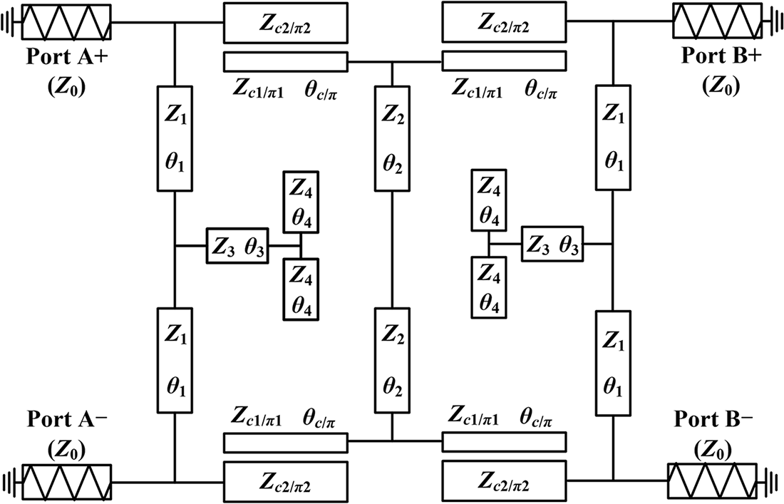
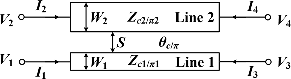
Figure 1 demonstrates the initial structure schematic of the proposed balanced UWB filter, and the electrical lengths of transmission lines and asymmetrical parallel-coupled lines are all 90° at the center frequency f 0. Ports A+ and A− define the differential input ports, whereas ports B+ and B− define the differential output ports, both with impedance Z 0 = 50 Ω. The presented construction of the initial balanced filter with an excellent sharp UWB filtering performance is mainly based on quarter-wavelength asymmetrical parallel-coupled transmission lines. The A-parameters of asymmetrical parallel-coupled transmission lines 1 and 2 are clearly specified in (1) [Reference Tripathi28] and correspond to c-mode characteristic impedance (Zc 1/c2) and π-mode characteristic impedance (Zπ 1/π2). Figure 2 shows the circuit model of asymmetrical parallel-coupled transmission lines. The letters θc and θπ express the c- and π-mode electrical lengths, respectively. The c- and π-mode voltage ratio between asymmetrical parallel-coupled transmission lines 1 and 2 is denoted as Rc and Rπ. It should be noted that (1) can also be applied to analyze symmetrical parallel-coupled transmission lines when Rc = −Rπ = 1.
 \begin{equation}\left[ {\begin{array}{*{20}{c}}
{{V_1}} \\
{{V_2}} \\
{{I_1}} \\
{{I_2}}
\end{array}} \right] = \left[ {\begin{array}{*{20}{c}}
{{a_{11}}}&{{a_{12}}}&{{b_{11}}}&{{b_{12}}} \\
{{a_{21}}}&{{a_{22}}}&{{b_{21}}}&{{b_{22}}} \\
{{c_{11}}}&{{c_{12}}}&{{d_{11}}}&{{d_{12}}} \\
{{c_{21}}}&{{c_{22}}}&{{d_{21}}}&{{d_{22}}}
\end{array}} \right]\left[ {\begin{array}{*{20}{c}}
{{V_3}} \\
{{V_4}} \\
{ - {I_3}} \\
{ - {I_4}}
\end{array}} \right]\end{equation}
Initial structure schematic of the proposed balanced UWB BPF.

Circuit model of asymmetrical parallel-coupled transmission lines.

 \begin{equation}{a_{11}} = {d_{11}} = \frac{{{R_\pi }\cos {\theta _c}}}{{{R_\pi } - {R_c}}} + \frac{{{R_c}\cos {\theta _\pi }}}{{{R_c} - {R_\pi }}}\end{equation}
 \begin{equation}{a_{22}} = {d_{22}} = - \left( {\frac{{{R_c}\cos {\theta _c}}}{{{R_\pi } - {R_c}}} + \frac{{{R_\pi }\cos {\theta _\pi }}}{{{R_c} - {R_\pi }}}} \right)\end{equation}
 \begin{equation}{a_{12}} = {d_{21}} = - \left( {\frac{{\cos {\theta _c}}}{{{R_\pi } - {R_c}}} + \frac{{\cos {\theta _\pi }}}{{{R_c} - {R_\pi }}}} \right)\end{equation}
 \begin{equation}{a_{21}} = {d_{12}} = \frac{{{R_c}{R_\pi }\cos {\theta _c}}}{{{R_\pi } - {R_c}}} + \frac{{{R_c}{R_\pi }\cos {\theta _\pi }}}{{{R_c} - {R_\pi }}}\end{equation}
 \begin{equation}{b_{12}} = {b_{21}} = {\text{j}}\left({\frac{{{R_\pi }{R_c}{Z_{c1}}\sin {\theta _c}}}{{{R_\pi } - {R_c}}} + \frac{{{R_c}{R_\pi }{Z_{\pi 1}}\sin {\theta _\pi }}}{{{R_c} - {R_\pi }}}} \right)\end{equation}
 \begin{equation}{b_{11}} = {\text{j}}\left( {\frac{{{R_\pi }{Z_{c1}}\sin {\theta _c}}}{{{R_\pi } - {R_c}}} + \frac{{{R_c}{Z_{\pi 1}}\sin {\theta _\pi }}}{{{R_c} - {R_\pi }}}} \right)\end{equation}
 \begin{equation}{b_{22}} = {\text{j}}\left({\frac{{{R_\pi }R_c^2{Z_{c1}}\sin {\theta _c}}}{{{R_\pi } - {R_c}}} + \frac{{{R_c}R_\pi ^2{Z_{\pi 1}}\sin {\theta _\pi }}}{{{R_c} - {R_\pi }}}} \right)\end{equation}
 \begin{equation}{c_{12}} = {c_{21}} = - {\text{j}}\left({\frac{{\sin {\theta _c}}}{{{Z_{c1}}\left( {{R_\pi } - {R_c}} \right)}} + \frac{{\sin {\theta _\pi }}}{{{Z_{\pi 1}}\left( {{R_c} - {R_\pi }} \right)}}} \right)\end{equation}
 \begin{equation}{c_{11}} = {\text{j}}\left({\frac{{{R_\pi }\sin {\theta _c}}}{{{Z_{c1}}\left( {{R_\pi } - {R_c}} \right)}} + \frac{{{R_c}\sin {\theta _\pi }}}{{{Z_{\pi 1}}\left( {{R_c} - {R_\pi }} \right)}}} \right)\end{equation}
 \begin{equation}{c_{22}} = {\text{j}}\left( {\frac{{\sin {\theta _c}}}{{{Z_{c1}}{R_\pi }\left( {{R_\pi } - {R_c}} \right)}} + \frac{{\sin {\theta _\pi }}}{{{Z_{\pi 1}}{R_c}\left( {{R_c} - {R_\pi }} \right)}}} \right)\end{equation}
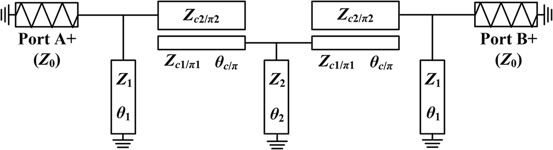
Based on the symmetric theory, the DM equivalent circuit configuration of initial UWB filter is depicted in Fig. 3. The A-matrix is selected to analyze the structure because the DM equivalent circuit is able to be viewed within a cascade structure with five parts. Figure 4 shows the DM equivalent circuit’s block diagram. Where [A]TL1 represents the A-matrix of the branch line (Z 1, θ 1), [A]CL represents the A-matrix of two-port asymmetrical parallel-coupled transmission line with two open-circuited ends, and [A]TL2 represents the A-matrix of microstrip section (Z 2, θ 2), and so forth. According to microwave network theory and (1), [A]TL1, [A]TL2, and [A]CL can be expressed as
 \begin{equation}{\left[ A \right]_{{\text{TL1}}}} = \left[ {\begin{array}{*{20}{c}}
1&0 \\
{{Y_1}}&1
\end{array}} \right]\end{equation}
DM equivalent circuit of the initial UWB filter.

 \begin{equation}{\left[ A \right]_{{\text{TL2}}}} = \left[ {\begin{array}{*{20}{c}}
1&0 \\
{{Y_2}}&1
\end{array}} \right]\end{equation}
 \begin{equation}{\left[ A \right]_{{\text{CL}}}} = \left[ {\begin{array}{*{20}{c}}
{\frac{{{M_1}}}{N}}&{\frac{{{M_2}}}{N}} \\[6pt]
{\frac{{{M_3}}}{N}}&{\frac{{{M_4}}}{N}}
\end{array}} \right]\end{equation}
The block diagram of the DM equivalent circuit.

with
 \begin{equation}\left\{ {\begin{array}{*{20}{c}}
{{Y_1} = \frac{1}{{{\text{j}}{Z_1}\tan {\theta _1}}}} \\
{{Y_2} = \frac{1}{{{\text{j}}{Z_2}\tan {\theta _2}}}}
\end{array}} \right.\end{equation}
and
 \begin{equation}\left\{ {\begin{array}{*{20}{l}}
{{M_1} = {c_{21}}{d_{12}} - {c_{11}}{d_{22}}} \\
{{M_2} = {b_{12}}{c_{21}} - {a_{11}}{d_{22}}} \\
{{M_3} = {c_{12}}{c_{21}} - {c_{11}}{c_{22}}} \\
{{M_4} = {a_{12}}{c_{21}} - {a_{11}}{c_{22}}} \\
{N = \left( \begin{gathered}
{a_{11}}{c_{12}}{d_{22}} - {a_{11}}{c_{22}}{d_{12}} - {a_{12}}{c_{11}}{d_{22}} \hfill \\
+ \, {a_{12}}{c_{21}}{d_{12}} + {b_{12}}{c_{11}}{c_{22}} - {b_{12}}{c_{12}}{c_{21}} \hfill \\
\end{gathered} \right)}
\end{array}} \right.\end{equation}
Further, the A-matrix of whole equivalent circuit under DM excitation can be calculated as
 \begin{align}
\left[ A \right] &= \left[ {\begin{array}{*{20}{c}}
{{A_{{\text{ddAA}}}}}&{{A_{{\text{ddAB}}}}} \\
{{A_{{\text{ddBA}}}}}&{{A_{{\text{ddBB}}}}}
\end{array}} \right] \nonumber\\
&= {\left[ A \right]_{{\text{TL1}}}} \times {\left[ A \right]_{{\text{CL}}}} \times {\left[ A \right]_{{\text{TL2}}}} \times {\left[ A \right]_{{\text{CL}}}} \times {\left[ A \right]_{{\text{TL1}}}}
\end{align}
where
 \begin{equation}\left\{ {\begin{array}{*{20}{l}}
{A_{{\text{ddAA}}}} = \dfrac{{\left( \begin{gathered}
{M_1}{M_4} + M_2^2 + {M_1}{M_3}{Y_1} \hfill \\
+ {M_2}{M_4}{Y_2} + {M_1}{M_2}{Y_1}{Y_2} + {M_2}{M_3}{Y_1}{Y_2} \hfill \\
\end{gathered} \right)}}{{{N^2}}} \\[6pt]
{A_{{\text{ddAB}}}} = \dfrac{{{M_1}{M_3} + {M_1}{M_2}{Y_2} + {M_2}{M_3}{Y_2}}}{{{N^2}}} \\[6pt]
{A_{{\text{ddBA}}}} = \dfrac{{\left( \begin{gathered}
{M_2}{M_4} + {M_3}{M_4} + 2{M_1}{M_4}{Y_1} + M_2^2{Y_1} \hfill \\
+ M_3^2{Y_1} + M_4^2{Y_2} + {M_1}{M_2}Y_1^2 + {M_1}{M_3}Y_1^2 \hfill \\
+ {M_2}{M_4}{Y_1}{Y_2} + {M_3}{M_4}{Y_1}{Y_2} + {M_2}{M_3}Y_1^2{Y_2} \hfill \\
\end{gathered} \right)}}{{{N^2}}} \\[6pt]
{A_{{\text{ddBB}}}} = \dfrac{{\left( \begin{gathered}
{M_1}{M_4} + M_3^2 + {M_1}{M_2}{Y_1} \hfill \\
+ {M_1}{M_3}{Y_1} + {M_3}{M_4}{Y_2} + {M_2}{M_3}{Y_1}{Y_2} \hfill \\
\end{gathered} \right)}}{{{N^2}}}
\end{array}} \right.\end{equation}
There is a relationship between the A- and S-matrices that can be transformed into each other, so the final S-parameters of the DM equivalent circuit of the initial UWB filter expressed in A-parameters are
 \begin{equation}\left\{ {\begin{array}{*{20}{c}}
{{S_{{\text{ddAA}}}} = \frac{{{{{A_{{\text{ddAB}}}}} \mathord{\left/
{\vphantom {{{A_{{\text{ddAB}}}}} {{Z_0} - {A_{{\text{ddBA}}}}{Z_0}}}} \right.
}\!{{Z_0} - {A_{{\text{ddBA}}}}{Z_0}}}}}{{{A_{{\text{ddAA}}}} + {{{A_{{\text{ddAB}}}}} \mathord{\left/
{\vphantom {{{A_{{\text{ddAB}}}}} {{Z_0} + {A_{{\text{ddBA}}}}{Z_0}}}} \right.
}\!{{Z_0} + {A_{{\text{ddBA}}}}{Z_0}}} + {A_{{\text{ddBB}}}}}}} \\[8pt]
{{S_{{\text{ddBA}}}} = \frac{2}{{{A_{{\text{ddAA}}}} + {{{A_{{\text{ddAB}}}}} \mathord{\left/
{\vphantom {{{A_{{\text{ddAB}}}}} {{Z_0} + {A_{{\text{ddBA}}}}{Z_0}}}} \right.
}\!{{Z_0} + {A_{{\text{ddBA}}}}{Z_0}}} + {A_{{\text{ddBB}}}}}}}
\end{array}} \right.\end{equation}
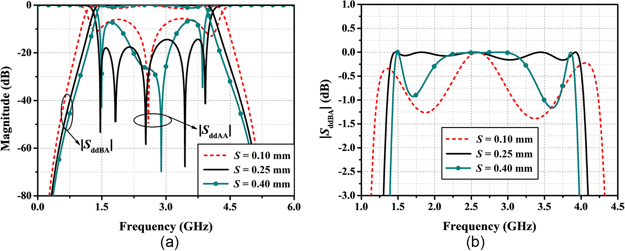
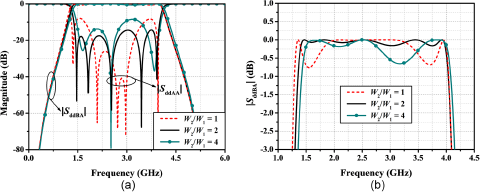
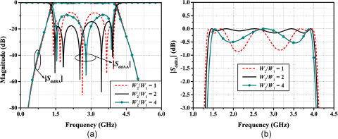
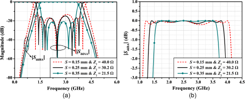
In order to investigate the influence of c- and π-mode of asymmetrical parallel-coupled microstrip lines and further determine the electrical parameters of this design, the effects of different S and W 2/W 1 on the performances of the proposed initial balanced UWB filter have been discussed. It can be seen from Fig. 5 that the filtering bandwidth decreases when S is raised from 0.1 to 0.4 mm. To achieve sharp UWB filtering characteristics, good in-band matching, and ripple responses, select S as 0.25 mm. Figures 6 and 7 show the effects of W 2/W 1 on the performances of the proposed initial balanced UWB filter when W 2 or W 1 is kept constant, respectively. When W 2/W 1 is equal to 2, excellent in-band matching characteristics have been presented. So the widths W 1 and W 2 of asymmetrical parallel-coupled lines 1 and 2 have been set at 0.4 and 0.8 mm, respectively. Moreover, it should be noted that the filtering bandwidth is less sensitive to the value of W 2/W 1, which is helpful to the precise control of the filtering bandwidth. Figure 8 demonstrates the responses of the initial balanced UWB filter with different filtering bandwidths. As can be seen in Fig. 8, the filtering bandwidth can be controlled by choosing the values of S and Z 2 while good in-band matching and ripple response can be obtained. However, the filtering bandwidth is thus also limited by the fabrication restrictions on the width of the slit and the microstrip line.
Effects of S on the performances of initial balanced UWB filter. (a) DM mixed S-parameters. (b) Ripple responses.

Effects of W 2/W 1 on the performances of initial balanced UWB filter when W 2 = 0.8 mm with W 1 change. (a) DM S-parameters. (b) Ripple responses.

Effects of W 2/W 1 on the performances of initial balanced UWB filter when W 1 = 0.4 mm with W 2 change. (a) DM S-parameters. (b) Ripple responses.

Responses of the initial balanced UWB filter with different filtering bandwidths. (a) DM S-parameters. (b) Ripple responses.

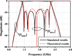
According to [Reference Tripathi and Chang29], Zc 1, Zc 2, Zπ 1, Zπ 2, Rc, and Rπ in (1) applied to analyze the asymmetrical parallel-coupled microstrip transmission lines can be determined as 161.8 Ω, 125.7 Ω, 62.5 Ω, 48.6 Ω, 1.05, and −0.74. Therefore, under the condition that S ddAA is equal to zero, when one of the values of Z 1 and Z 2 is selected, the other one will be determined by (9). In order to illustrate the effectiveness and reliability of the derived formulas, Fig. 9 demonstrates the comparison of the theoretical calculation and simulated results of the initial balanced UWB filter, and it can be seen from Fig. 9 that the theoretical calculation and simulated results are in agreement, including similar filtering bandwidths and frequency selectivity, as well as the same number of transmission poles. For CM noise suppression, CM interferences can be effectively suppressed by loading the T-type stubs on the symmetrical axis of the proposed initial BPF, which have no influence on the DM performance of the balanced filter.
Comparison of the theoretical calculation and simulated results of the initial balanced UWB filter.

Different-mode harmonic suppression
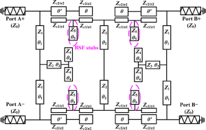
In order to enhance out-of-band restraint properties with third harmonic suppression, a simple design method of integrating bandstop filters (BSF) into the original BPF without increasing the circuit size is described in this section. The third harmonic of the quarter-wavelength resonator should have a voltage null point in accordance with the planar transmission line theory. The voltage null point is selected as the exciting position to load the BSF branches corresponding to the third harmonic to avoid the third harmonic of balanced UWB filter from being excited and subsequently successfully suppressed, enhancing out-of-band rejection performance. The structure diagram of the developed balanced UWB filter with DM harmonic suppression is demonstrated in Fig. 10. Based on distribution voltage waveforms during the third harmonic, there is a voltage-null point where it should satisfy
 \begin{equation}{\theta \mathord{\left/
{\vphantom {\theta {\left( {\theta + \theta {^{\prime}}} \right)}}} \right.
} {\left( {\theta + \theta {^{\prime}}} \right)}} = {1 \mathord{\left/
{\vphantom {1 3}} \right.
} 3}\end{equation}
Schematic of balanced UWB BPF with DM harmonic suppression.

The BSF branch used in this design is open-circuited stubs of one-quarter wavelength electrical length corresponding to the third harmonic, which also means θ 5 = 30° corresponding to the fundamental operating frequency f 0. When θ 5 approaches 30°, the input impedance Z in looking into the open-circuited stub for the third harmonic is obtained
 \begin{equation}{Z_{{\text{in}}}} = - {\text{j}}{Z_5}\cot{\theta _5}\end{equation}
As a consequence, the input impedance Z in = ∞, which can exhibit a band-stop state to suppress the third harmonic.
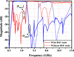
The simulated mixed S-parameters of UWB filter with or without BSF stubs are displayed in Fig. 11 to confirm the validity of the development process when Z 1 = 103.3 Ω and Z 2 = 30.2 Ω. The filter schematic without BSF stubs is shown in Fig. 1, and the filter schematic with BSF stubs is shown in Fig. 10. As can be observed from Fig. 11, the proposed balanced UWB BPF with BSF stubs has a similar sharp UWB filtering performance in transition band to initial BPF without BSF stubs, and matching characteristics in the passband are improved. It ought to be pointed out that loading the BSF stub at the third harmonic acts as a bandstop filtering section to reduce the third harmonic, enhancing out-of-band rejection. Furthermore, this simple harmonic suppression method of integrating BSF stubs into the initial BPF can be extended to be widely applied for other harmonics suppression and does not increase the overall circuit size compared to conventional cascaded filters [Reference Huang and Cheng30–Reference Wu, Zhuang, Liu, Deng and Ghassemlooy33]. Therefore, this design method can easily be transplanted to various types of balanced component designs.
Mixed S-parameters of balanced UWB BPF with or without BSF stubs.

Design procedure
Based on the above analysis, the design procedures of the proposed balanced UWB BPF with third harmonic suppression characteristics are summarized as follows:
Step 1: Identify the specifications of the balanced filter, such as the center frequency, the filtering bandwidth, and harmonic suppression characteristics.
Step 2: According to the foregoing analysis of the circuit schematic of the initial balanced BPF, the derived (9) can be used to design the filter with Matlab calculation.
Step 3: Simulate and determine the characteristic impedance value of transmission lines and electrical parameters of the asymmetrical parallel-coupled lines.
Step 4: Calculate the position of the voltage-null point at the third harmonic and the length of the BSF stub by (10) and (11). Integrate BSF stubs into the initial balanced BPF for third harmonic suppression.
Step 5: If the filter does not perform well, return to Step 2 and fine-tune the parameters to optimize the characteristics.
Experimental verification
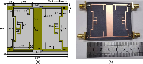
In this section, a balanced UWB BPF prototype operating at the center frequency f 0 = 2.6 GHz with harmonic suppression characteristics is designed, fabricated, and measured for validation, which is capable of being utilized in balanced UWB RF communication networks to improve the filtering selectivity and out-of-band suppression performance. The developed balanced UWB filter is constructed using the aforementioned design approaches on the F4B substrate with a thickness of 1.5 mm, a dielectric constant of 2.65, and a loss tangent of 0.003. Figure 12(a) depicts the layout of the designed balanced UWB filter. The final physical dimensions are attained following optimization using Ansoft HFSS software. Figure 12(b) shows a photograph of the completed filter. The overall circuit dimension is 58.7 mm × 50.0 mm (0.75λ g × 0.64λ g, where λ g is the guided wavelength at f 0).
(a) Layout and (b) photograph of the proposed balanced UWB BPF.

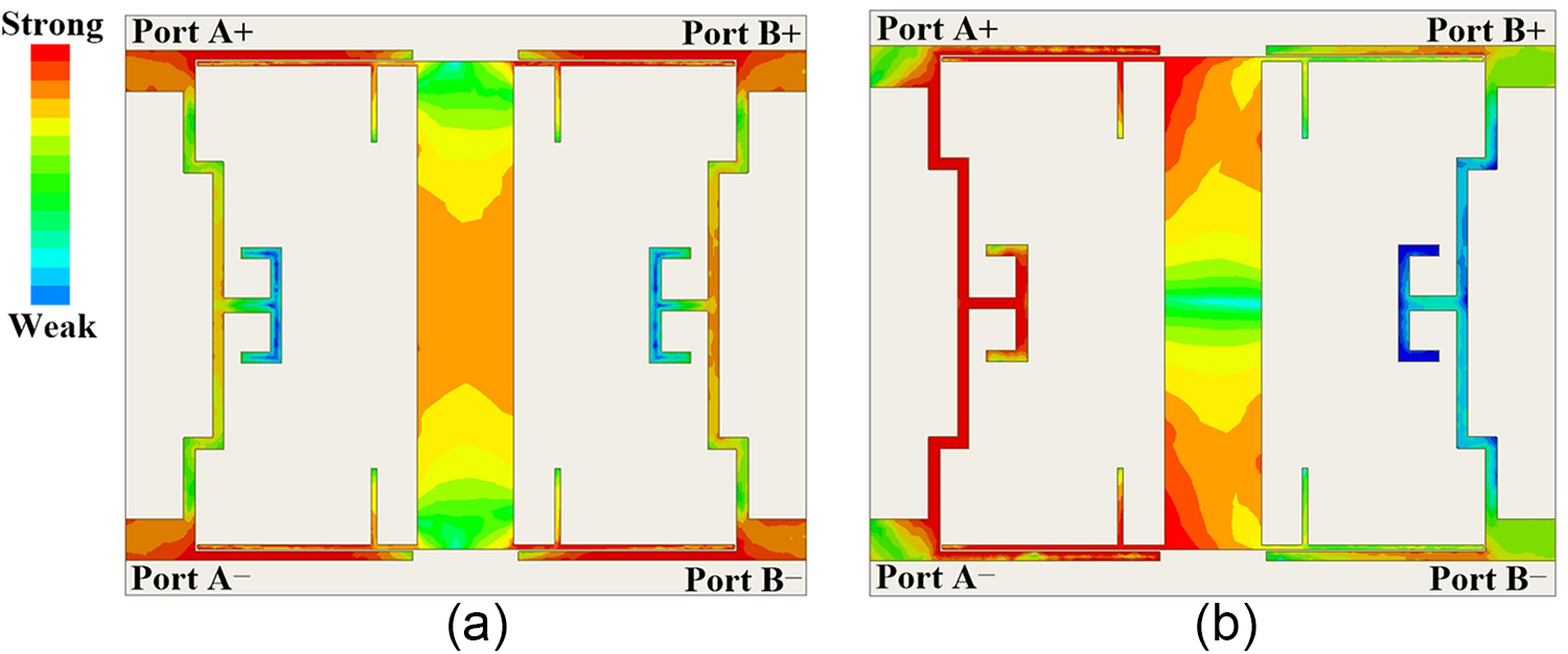
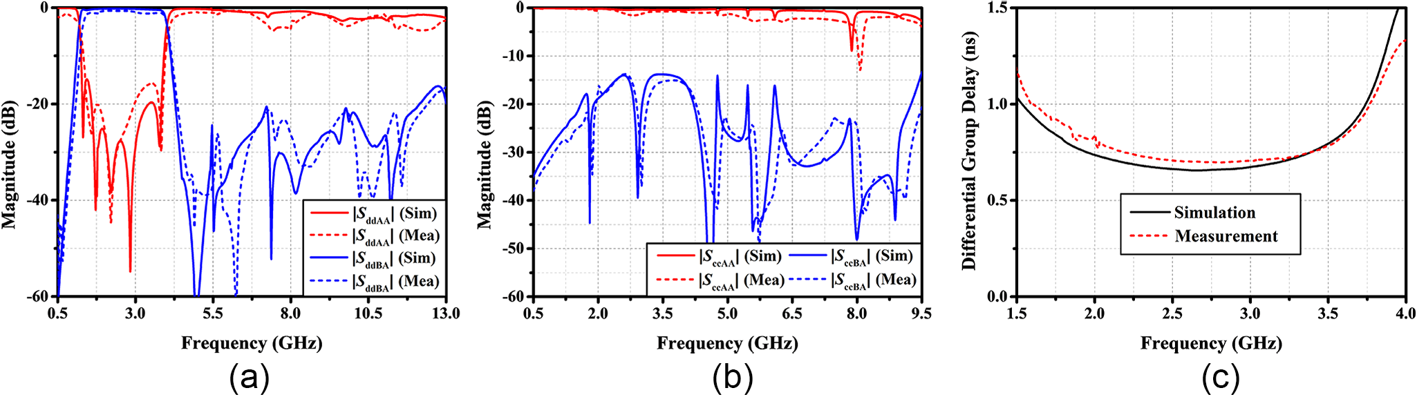
The current density distributions of the proposed balanced UWB BPF at f 0 are shown in Fig. 13. When the signal is input from the differential ports A+ and A−, under the DM excitation, the majority of the signal is able to achieve transmission to the differential output ports B+ and B−. For CM excitation, due to the symmetry of the circuit structure, the CM noise is basically reflected back, resulting in the CM suppression response. Figure 14 displays the simulated and measured results of the proposed high-selectivity balanced UWB BPF with harmonic suppression, which are consistent with each other. For DM excitation, the center frequency of the presented balanced UWB filter is 2.6 GHz. The measured minimum DM IL is 0.68 dB, while 3-dB fractional bandwidth (FBW) is on the verge of 108% (from 1.31 to 4.02 GHz). The shape factor is defined as the ratio of 20-dB bandwidth to 3-dB bandwidth, which is 1.17, identifying the sharp filtering selectivity. The measured DM return losses are greater than 15 dB (i.e., |S ddAA| < − 15 dB) from 1.38 to 3.92 GHz. Furthermore, out-of-band rejection of the proposed balanced UWB BPF is superior to 20 dB in the upper stopband from 4.35 to 12.4 GHz with the third harmonic suppression characteristics. As seen in Fig. 14(b), for CM excitation, it acts as a UWB bandstop filter, and the CM suppression level is greater than 14 dB from DC to 9.50 GHz. The measured in-band differential group delay is flat as low as 1.0 ns within the DM passband and becomes higher closer to the lower and upper edges of the DM passband, as shown in Fig. 14(c).
Current density distributions of the proposed balanced UWB BPF at f 0. (a) DM excitation. (b) CM excitation.

Simulated and measured results of the proposed balanced UWB BPF with harmonic suppression. (a) DM responses. (b) CM responses. (c) DM group delay.

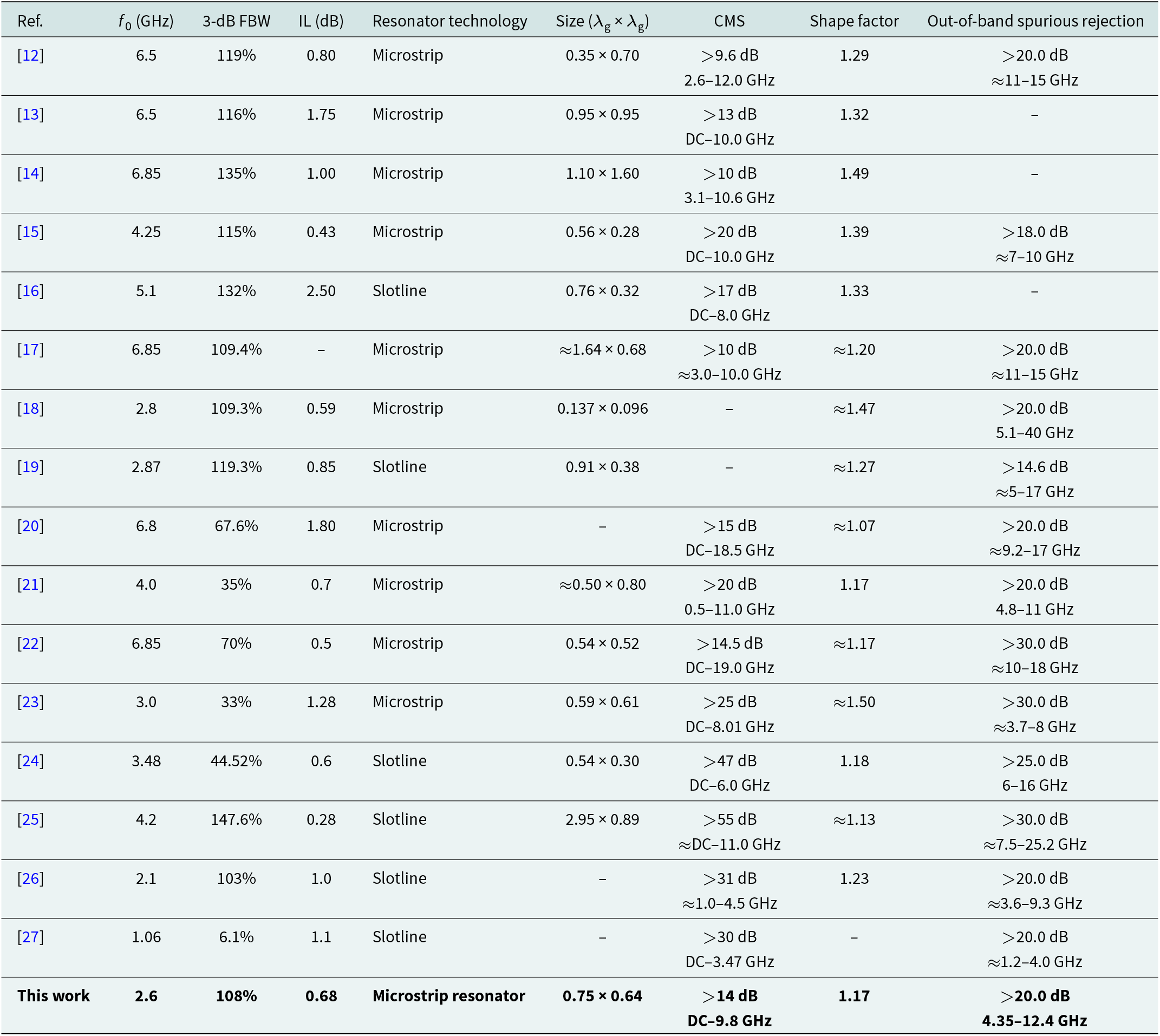
The performance comparisons between the presented balanced UWB filter and the reported balanced UWB filters are given in Table 1. Compared with reported filters, the proposed balanced UWB BPF has the advantages of small IL and sharp filtering performance. Furthermore, the improved out-of-band rejection of the filter with harmonic suppression has been realized in this design. Due to its outstanding capabilities in terms of high selectivity, CM rejection, harmonic suppression characteristics, the designed UWB BPF is highly recommended. It is expected that the proposed filter is capable of being utilized in balanced UWB communication systems to improve the filtering selectivity and out-of-band rejection performance.
Performance comparisons between the proposed balanced BPF and previous balanced UWB filters

Conclusion
This paper has presented a high-selectivity UWB BPF based on asymmetrical parallel-coupled microstrip lines with third harmonic suppression characteristics. A simple and effective method of third harmonic suppression without increasing the circuit size has been described, which is to load a band-stop filtering stub corresponding to the third harmonic at the voltage null point on the quarter-wavelength resonators. Compared with the existing balanced UWB BPFs, the proposed filter achieves smaller IL, sharper filtering selectivity, and harmonic suppression characteristics not currently available in other balanced UWB filters.
Acknowledgements
This work was supported by the National Natural Science Foundation of China under Grant 61871417 and Grant 52471371; the Liaoning Revitalization Talents Program under Grant XLYC2007024; the Basic Research Project of the Department of Education of Liaoning Province for Universities under Grant LJ212410151023; and the Open Fund of Liaoning Key Laboratory of Radio Frequency and Big Data for Intelligent Applications.
Competing interests
The authors report no conflict of interest.

Shipeng Zhao received the B.Eng. degree in electronic information science and technology from Dalian Maritime University (DMU), Liaoning, China, in 2021. He is currently working toward the Ph.D. degree in information and communication engineering at Dalian Maritime University. His current research interests include balanced components and negative group delay circuits.

Zhongbao Wang received the Ph.D. degree in communication and information systems from DMU, China, in 2012. He is currently a Full Professor with the School of Information Science and Technology, DMU. From 2014 to 2018, he was a Postdoctoral Fellow with Beijing University of Posts and Telecommunications, China. From 2019 to 2020, he was a Visiting Scholar with National University of Singapore, Singapore. He has authored more than 160 journal papers. He is currently serving as a Technical Reviewer for the IEEE Trans. on Circuits and Systems, MTT, MWTL, MOTL, and so on. His current research interests include balanced RF components and CP antennas.

Hongmei Liu received the Ph.D. degree in communication and information systems from DMU, China, in 2016. She is currently a Full Professor with the School of Information Science and Technology, DMU. Her current research interests include passive microwave circuits, reconfigurable RF components, and CP microwave antennas.

Shaojun Fang received the Ph.D. degree in communication and information systems from DMU, China, in 2001. Since 1982, he has been at DMU, where he is currently the Head Professor with the School of Information Science and Technology. He has authored or co-authored four books and over 180 journal and conference papers. His recent research interests include passive RF components and antennas.