1. Introduction
Since the 1990s, with the development of aerodynamics theory, new materials and microelectro mechanical technology, microair vehicles (MAV) have entered the trend of development, and all kinds of aircraft have been studied all over the world [Reference Gerdes, Gupta and Wilkerson1]. The flight mode of the MAV includes fixed wing, rotor wing and flapping wing, etc. Among them, flapping microair vehicles (FMAV) can achieve vertical take-off and landing, hovering, side-flying and inverted flying [Reference Couceiro, Luz, Figueiredo and Ferreira2], and some of them can glide, high-speed flight and long-distance cruise [Reference Rifaï, Guerrero, Marchand and Poulin3]. Due to the bionic shape conditions, FMAV has good invisibility, low noise and high maneuverability. It has great prospect in military investigation, scientific research and civil field [Reference Han, Hui, Tian and Cheng4].
As the only mammal that can fly in nature, bats have the advantages of high flight efficiency and strong maneuverability, becoming one of the main imitation objects in the design of FMAV [Reference Bie, Li, Xiang, Li, Kan and Sun5]. Related research on bat-like robot has attracted widespread attention from researchers around the world [Reference Shyy, Aono, Chimakurthi, Trizila, Kang, Cesnik and Liu6]. Representative achievements are mainly: Memory alloy joint bat-like robot of Pontificia Universidad Javeriana [Reference Colorado, Rossi, Barrientos, Parra, Devia and Patino7], Brown University’s multi degrees of freedom bat-like robot [Reference Joseph, Sharon and Kenneth8, Reference Hubel, Hristov, Swartz and Breuer9], B2 developed by the University of Illinois and California Institute of Technology [Reference Ramezani, Chung and Hutchinson10, Reference Ramezani, Shi, Chung and Hutchinson11], Bionic Flying Fox of Festo, etc.
One of the key points in the research field of bat-like robot is the calculation of its aerodynamic force. Unlike insects [Reference Jafferis, Helbling, Karpelson and Wood12] and birds [Reference Fei, Tu, Yang, Zhang and Deng13], which mostly rely on the reciprocating flapping of fixed-shaped wings to generate lift and drag to fly, the forelimbs and hindlimbs of bats are connected by the same flexible membrane. During the flight, the area of the membrane is changed by the movement of the joints [Reference Norberg and Rayner14], the membrane unfolds to increase the positive lift when flapping downward and folds to reduce drag when flapping upward. Although this complex flight mechanism improves the flying efficiency and flexibility of bats, it also greatly increases the difficulty of aerodynamic theoretical calculation and becomes a limiting factor that hinders the design and control of bat-like robot. So, there are few papers to analyze the aerodynamic theory of bat-like robot. At present, there are two main research directions of bat-like robot. One is to start with the kinematics of bats and optimize the flapping mechanism design of bat-like robot based on actual bat flight data [Reference Bender, Guo, Powell, Kurdila and Müller15, Reference Hoff, Ramezani, Chung and Hutchinson16]. The other is to start with the design of flexible membrane to study the influence of deformable membrane on aerodynamics [Reference Colorado, Barrientos, Rossi, Bahlman and Breuer17]. For example, lixuepeng et al. used wind tunnel to verify that deformability had a significant effect on the adjustment of posture during gliding, the results indicate that the aerodynamic effect produced by the flexible deformable membrane can enhance the rationality and stability of the glide strategy [Reference Li, Wang, Tang, Wang, Bai, Zhao and Bai18]. Ismail et al. had found through experiments that the flexible membrane could greatly improve the lift; meanwhile, it would also produce great drag and affect the overall flight efficiency [Reference Ismail, Zulkifli, Abdullah, Hisyam Basri and Shah Abdullah19]. David Colmenares et al. explored the influence of flexible wing twist on lift and flight efficiency, and proposed that reducing the angle of attack toward the tip and increasing wing twist would increase lift-drag ratio and improve wing efficiency, but it would also reduce the total lift coefficient of the wing [Reference Colmenares, Kania, Zhang and Sitti20]. Through combing and summarizing, it is found that most of the existing research on the field of flexible membrane deformation is based on experimental analysis and research, and there is no literature report on the related research on the aerodynamic theory calculation method of flexible deformation. This also leads to the lack of theoretical support for the structural optimization design and control of bat-like robots, which seriously limits the development of robots.
In this paper, based on the deformation characteristics of the flexible membrane of the bat-like robot, the configuration and motion law of the bionic wing are described. Then, considering that there is a unique way of movement for bat wings, that is, the wings will be folded and unfolded during the flapping process (unfolding when flapping downward and folding when flapping upward), combined with the passive torsion around the leading edge axis under the action of aerodynamic force, a calculation model for chord length, passive torsion angle and relative velocity is constructed. What’s more, the BEM is used to ensure the applicability of the quasi-steady state model, and the attached vortex mechanism is used to calculate the circulation aerodynamic forces (the translational circulation and the rotational circulation); at the same time, the influence factors such as virtual mass force and inertia force are also considered, so a set of aerodynamic calculation model is established. Finally, fluid-structure interaction (FSI) model is simulated by XFlow, and the error comparison between theoretical calculation and simulation calculation under different working conditions is given to verify the correctness of the algorithm.
2. Analysis of the configuration and motion law of the wing
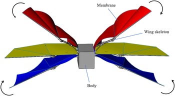
According to the characteristics of the bat, this paper carries out the bionic design of the structure and the modeling of the movement mode, so that it can realize the movement form of wings unfolding when flapping downward and folding when flapping upward. The deformation of the flexible wing studied in this paper includes two parts: active deformation and passive deformation. Among them, the passive deformation is realized by the flexible deformation of the membrane and the active deformation is realized by the folding and unfolding of the watt six-bar linkage mechanism to drive the wing to move, as shown in Fig. 1. In the figure, three colors of yellow, red and blue are used to show the movement of the wing and the deformation of the membrane during the initial position of the wing, the downward and the upward process.
The movement and deformation of wing.

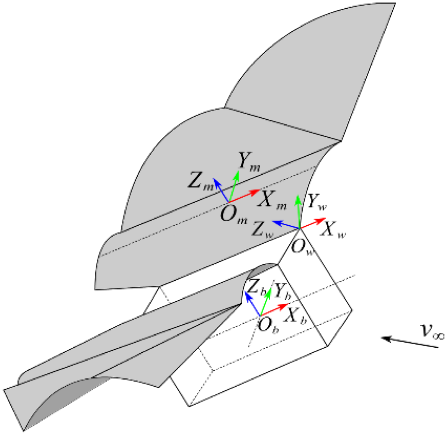
In order to carry out aerodynamic calculation, the coordinate system of bat-like robot is established, as shown in Fig. 2. The principles of establishing a coordinate system are as follows:
Coordinate system definition.

-
1. The Body coordinate system Ob-XbYbZb is fixed at the center of gravity of the Body (in order to facilitate the observation of the coordinate system, the rectangular block is used to replace the detailed structure of the Body part). The ObXb axis is parallel to the Body and points to the head of the model. The ObYb axis is perpendicular to the Body and points to the wing; ObZb axis is perpendicular to the Body upwards; XbObZb plane is the symmetry plane of the whole model.
-
2. Taking the right wing as an example, the coordinate system of flapping wing Ow-XwYwZw is located at the leading edge shoulder of the wing, and the origin Ow is located at the shoulder joint. OwXw axis points to the head of the model along the flapping axis. OwYw axis points to the wing tip along the tangential direction of leading edge axis. OwZw is determined according to the right-hand rule; YwOwZw plane is the flapping plane of wings.
-
3. Taking the right wing as an example, the coordinate system Om-XmYmZm is located on the membrane. Since the membrane is made of thin film, and it belongs to the symmetric membrane, and the pressure center of the symmetric membrane is also the aerodynamic center [Reference Gabiccini, Bicchi, Prattichizzo and Malvezzi21], so the origin Om is located at the pressure center, and the OmXm axis points to the leading edge axis along the chord direction of the membrane. OmZm axis is vertical to the direction of the membrane upward; OmYm is determined according to the right-hand rule, where the XmOmYm surface is the surface of the membrane (because the membrane needs to be divided into strips later, this surface is actually the surface of each strip).
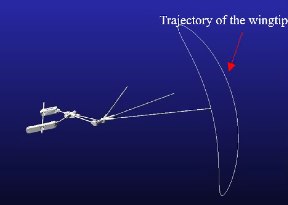
The trajectory of the wingtip in one cycle is simulated as shown in Fig. 3. It can be seen from Fig. 3 that the wingtip’s trajectory is crescent-shaped, indicating that there is a lateral displacement of the wings during the reciprocating flapping process, that is, the wing membrane area will change during the movement.
The trajectory of the wingtip.

The motion law of the membrane (flapping motion and deformation motion) will be explained below:
The flapping angle of the membrane changes with time as follows:
 \begin{equation}\theta _{o}\!\left(t\right)=A_{f}\sin\!(2\pi ft)\end{equation}
where θ 0 is the flapping angle, A f is the amplitude of flapping angle, f is the flapping frequency.
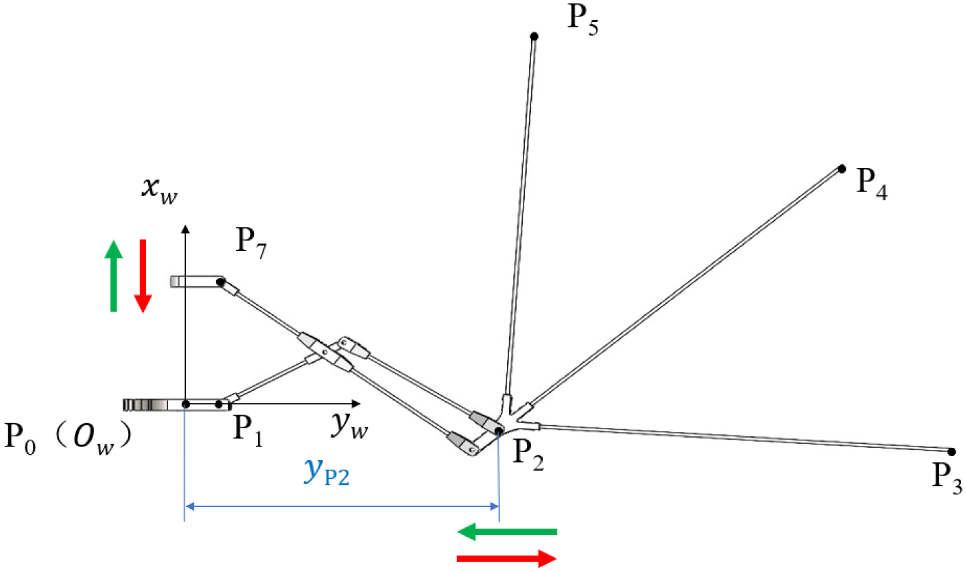
The watt six-link structure diagram with wings folding and unfolding is shown in Fig. 4. In the figure, point P 0 is located at the origin O w of the wing flapping coordinate system (O w -X w Y w Z w ). Points P 1∼P 5 are the connection points between the wing skeleton and the membrane, and point P 7 is the movement point that drives the deformation of the wing skeleton. The variable y P2 marked in the figure represents the displacement of wing deformation movement. The red and green arrows indicate the direction of movement of the wing skeleton.
The watt six-link structure diagram.

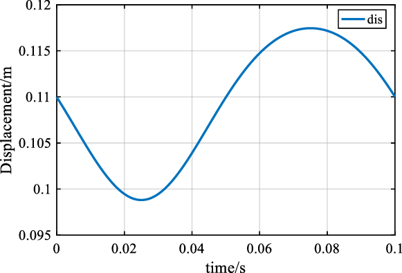
The displacement(y P2) curve of active deformation is obtained through calculation, as shown in Fig. 5.
The displacement curve of active deformation.

3. Aerodynamic calculation method of flexible deformable wing
3.1. Related parameters
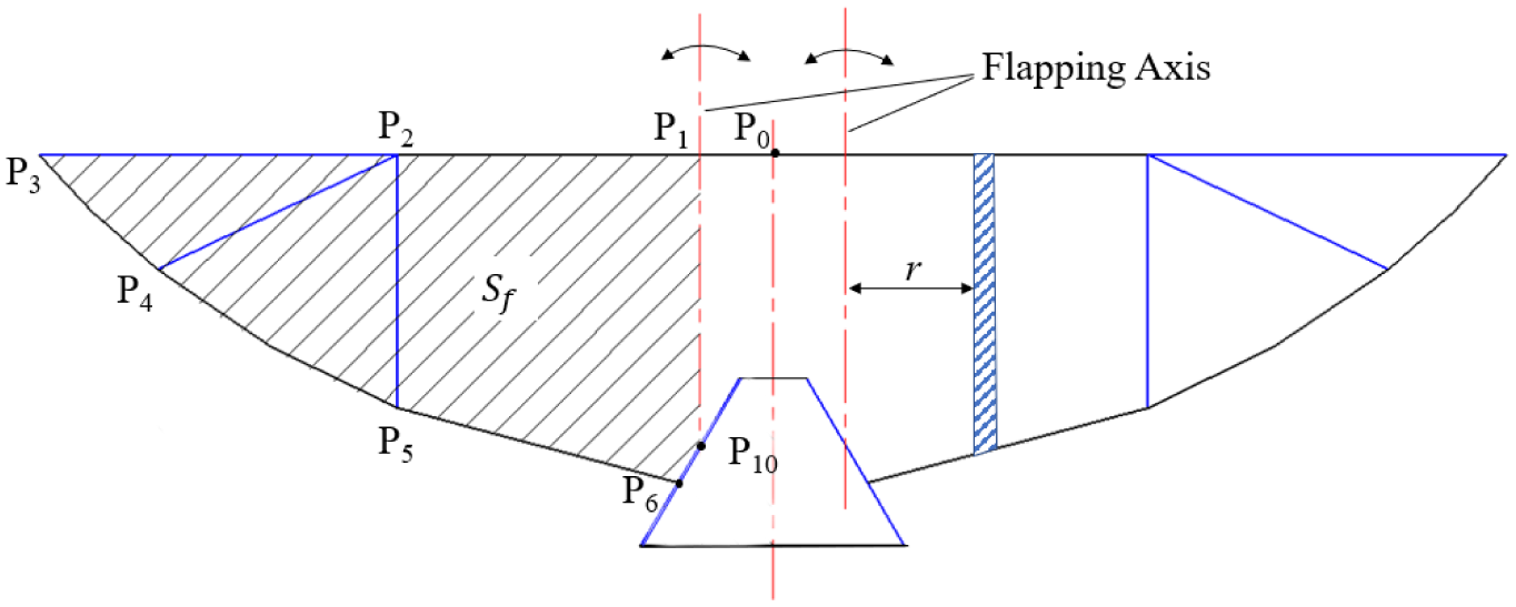
The chord length and relative velocity of membrane are the key parameters to calculate aerodynamic force. The membrane will deform with the movement of the wing, so the chord length and relative velocity of each position are different at each time. It is necessary to use BEM to divide the strip of the membrane and calculate the chord length and relative velocity of each strip in real time to calculate the instantaneous aerodynamic force. Figure 6 is the concept diagram of the membrane, in which the shape of the membrane is shown on the left side of the flapping axis, and the strip division is shown on the right side of the flapping axis.
Shape and strip division of membrane.

3.1.1. Calculation of membrane structure parameters
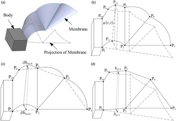
In the process of bat flapping, the membrane will produce a certain degree of spatial deformation due to its movement and elasticity, which can be divided into two parts: The first part is that because the wing skeleton flaps around the flapping axis, but the tail remains stationary, there will be an angle between the two, but the membrane is stuck to the wing skeleton and tail at the same time, so there will be a height difference between the leading edge and the trailing edge of the membrane relative to the initial plane. The second part is the elastic deformation of the membrane because of the aerodynamic force. To facilitate understanding, the deformation of the membrane is decomposed for illustration, as shown in Fig. 7.
The decomposition of membrane deformation.

Figure 7(a) represents the three-dimensional model diagram of the membrane in the downward process, including the deformation of the membrane and the projection of the membrane on the initial plane (projection is represented by dotted lines). Figure 7(b) shows the model in the downward process of the membrane, which is used to explain the deformation of the membrane, including the deformation diagram of the membrane and the projection diagram of the initial plane; Fig. 7(c) and (d) are schematic diagrams of the deformation of the membrane in Fig. 7(b) after decomposition (separated along the plane P 1 P 2 P 3 P 4 P 5 P 6 P 10), where Fig. 7(c) represents the elastic deformation of the membrane because of the aerodynamic force; Fig. 7(d) represents the height difference between the torsional deformation of the leading and trailing edges of the membrane relative to the initial plane (the plane composed of dotted lines).
In Fig. 7,
 $\varphi$
(r, t) is the angle of the strip (The strip with a distance r from the flapping axis P
1
P
10 at time t) relative to the initial plane, which is defined as the passive torsion angle. Its physical significance is the angle between the strip string and the flapping axis after the membrane twisted around the leading edge axis. h
Pr1 is the height of the leading edge due to flapping; h
Pr2 is the height of the trailing edge due to flapping; Δh
head is the height of the leading edge due to the flexible deformation of the membrane; Δh
back is the height of the trailing edge due to the flexible deformation of the membrane. The above deformation parameters (
 $\varphi$
(r, t), h
Pr1, h
Pr2, Δh
head, Δh
back, etc.) all represent the deformation of the membrane, so these variables are located on the membrane plane and in the membrane coordinate system(O
m
-x
m
y
m
z
m
) .
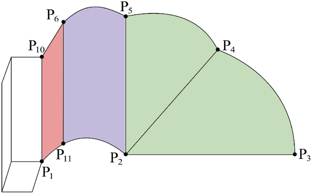
Due to the particularity of the bat wing structure, the deformation of the side membrane fixed to the tail, the arm membrane of the middle section, and the hand membrane of the wing hand part are different, so the research needs to be divided into three parts [Reference Joshi, Jaiman, Li, Breuer and Swartz22], as shown in Fig. 8.
The membrane is divided into three parts.

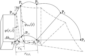
The first part (P 1 P 10 P 6 P 11) is the part connected with the membrane and the body, in which P 1 P 10 is connected with the body and P 10 P 6 is connected with the tail, both of which do not produce deformation, so this part only needs to calculate the deformation of the leading edge. The second part(P 11 P 6 P 5 P 2) is the middle part of the wing; in this part, two equivalent deformations should be considered and calculated simultaneously. The third part(P 2 P 5 P 4 P 3) is the part where the membrane is connected with the wing hand; this part only needs to calculate the deformation of the trailing edge.
First, for the first part, analytical diagram of bat membrane deformation is shown in Fig. 9. In the figure, r represents the distance between the strip and the flapping axis P
1
P
10;
 $\varphi$
(r, t) is the passive torsion angle of the strip at this moment where the distance from the flapping axis is r; r
P6 represents the distance between the strip P
6
P
11 and the flapping axis;
 $\varphi$
P6(t) represents the passive torsion angle of the strip where P
6
P
11 is located, which is also the largest passive torsion angle (absolute value) of the first part; θ
0 is the flapping angle; Δh
head is the height formed by the flexible deformation of the membrane from the leading edge of the strip at a distance r from the flapping axis.
Analytical diagram of bat membrane deformation.

P 1 P 2 is the leading edge of the membrane, which will be deformed by aerodynamic force. For calculation, P 1 P 2 is assumed to be a beam structure (a beam with a large amount of elastic deformation) with both ends fixed instantaneously. The beam is subjected to uniform force (assuming the aerodynamic force as uniform force), which will produce bending deformation, and its height due to elastic deformation is:
 \begin{equation}\Delta h_{\text{lead}}=\frac{\frac{q}{2}\left(\frac{1}{12}r^{4}-\frac{r_{P1P2}}{6}r^{3}\right)+\frac{q{r_{P1P2}}^{3}}{24}r}{\text{EI}_{\text{lead}}}\end{equation}
where EI lead is the bending rigidity of the leading edge; q is the uniform aerodynamic load; r P1P2 is the distance between P 1 and P 2.
Through the geometric relationship in Fig. 9, the expressions of chord length and passive torsion angle can be obtained:
 \begin{equation}c\left(r,t\right)=\sqrt{\left(2r\cdot \sin \frac{\theta _{o}}{2}-\text{sign}\left(\theta _{o}\frac{d\theta _{o}}{dt}\right)\Delta h_{\text{lead}}\right)^{2}+\left(P_{1}P_{10}+r\tan 30^{\circ}\right)^{2}}, 0\leq r\leq r_{P6}\left(t\right)\end{equation}
 \begin{equation}\varphi \left(r,t\right)=\pm \arctan \frac{2r\cdot \sin \frac{\theta _{o}}{2}-\text{sign}\left(\theta _{o}\frac{d\theta _{o}}{dt}\right)\Delta h_{\text{lead}}}{P_{1}P_{10}+r\tan 30^{\circ}}, 0\leq r\leq r_{P6}\left(t\right)\end{equation}
Next, calculate the second part, that is r P6(t) ≤r ≤P 0 P 1. The schematic diagram of the structure of this part is shown in (c)and (d) in Fig. 7. Similar to the deformation of the leading edge, the trailing edge part P 5 P 6 is also assumed to be a beam structure with both ends fixed instantaneously, and then, the height of the leading and trailing edges due to elastic deformation are:
 \begin{equation}\Delta h_{\text{lead}}=\frac{\frac{q}{2}\left(\frac{1}{12}r^{4}-\frac{r_{P1P2}}{6}r^{3}\right)+\frac{q{r_{P1P2}}^{3}}{24}r}{\text{EI}_{\text{lead}}}\end{equation}
 \begin{equation}\Delta h_{\text{back}}=\frac{\frac{q}{2}\left(\frac{1}{12}\left(r-r_{P6}\right)^{4}-\frac{r_{P5P6}}{6}\left(r-r_{P6}\right)^{3}\right)+\frac{q{r_{P5P6}}^{3}}{24}\left(r-r_{P6}\right)}{\text{EI}_{\text{back}}}\end{equation}
where EI back is the bending rigidity of the trailing edge; r P5P6 is the distance between P 5 and P 6.; r P6 is the distance between P 6 and flapping axis.
The height of any point on the leading edge and the height of the corresponding trailing edge point:
 \begin{equation}h_{Pr1}=\frac{h_{P2}}{r_{P1P2}}r_{Pr1}=2r_{Pr1}\cdot \sin \frac{\theta _{o}}{2}\end{equation}
 \begin{equation}h_{Pr2}=\frac{r_{Pr2}-r_{P6}}{r_{P1P2}-r_{P6}}h_{P2}\end{equation}
The projection on horizontal plane of the chord length formed by the connecting point P r1 and P r2:
 \begin{equation}P'_{\!\!r1}P'_{\!\!r2}=P_{2}P_{5}+\left(\frac{r_{P1P2}-r_{Pr1}}{r_{P1P2}-r_{P6}}\right)\left[\left(r_{P6}\cdot \tan 30^{\circ}+P_{1}P_{10}\right)-P_{2}P_{5}\right]\end{equation}
The height difference between P r1 and P r2 is:
 \begin{equation}h_{Pr2Pr1}=\left(h_{Pr2}-\text{sign}\left(\theta _{o}\frac{d\theta _{o}}{dt}\right)\Delta h_{\text{back}}\right)-\left(h_{Pr1}-\text{sign}\left(\theta _{o}\frac{d\theta _{o}}{dt}\right)\Delta h_{\text{lead}}\right)\end{equation}
So, the expressions of chord length and passive torsion angle can be obtained:
 \begin{equation}\varphi \left(r,t\right)=\mathrm{atan} \left(\frac{h_{Pr2Pr1}}{P'_{\!\!r1}P'_{\!\!r2}}\right),r_{P6}\leq r\leq r_{P1P2}\end{equation}
 \begin{equation}c\left(r,t\right)=P_{r1}P_{r2}=\sqrt{{h_{Pr2Pr1}}^{2}+\left(P'_{\!\!r1}P'_{\!\!r2}\right)^{2}},r_{P6}\leq r\leq r_{P1P2}\end{equation}
Finally, for the third part, that is the torsion angle of the membrane between r≥ P 1 P 2, because this part is connected with the wing hand part, and the skeleton layout of the wing hand is fixed, the chord length of this part is related to the shape of the wingtip
For this part, the height of the trailing edge due to elastic deformation is:
 \begin{equation}\Delta h_{\text{hand}}=\frac{\frac{q}{2}\left(\frac{1}{12}\left(\frac{r-r_{P1P2}}{\cos \varphi _{\text{hand}}}\right)^{4}-\frac{1}{6}\frac{r_{P2P3}}{\cos \varphi _{\text{hand}}}\left(\frac{r-r_{P1P2}}{\cos \varphi _{\text{hand}}}\right)^{3}\right)+\frac{q}{24}\left(\frac{r_{P2P3}}{\cos \varphi _{\text{hand}}}\right)^{3}\left(\frac{r-r_{P1P2}}{\cos \varphi _{\text{hand}}}\right)}{\text{EI}_{\text{hand}}}\end{equation}
where
 \begin{equation}\cos \varphi _{\text{hand}}=\frac{r_{P2P3}}{\sqrt{\left(r_{P2P3}\right)^{2}+\left(r_{P2P5}\right)^{2}}}\end{equation}
So, the expressions of chord length and passive torsion angle can be obtained:
 \begin{equation}c\left(r,t\right)=\sqrt{\left(P_{2}P_{5}\cdot \left(1-\left(\frac{r-r_{P1P2}}{r_{\max }-r_{P1P2}}\right)^{I}\right)\right)^{2}+\left(\Delta h_{\text{hand}}\right)^{2}}, r\geq r_{P1P2}\end{equation}
where I is the wingtip shape index (I reflects the wingtip shape).
 \begin{equation}\varphi \left(r,t\right)=\mathrm{atan} \left(\frac{\Delta h_{\text{hand}}}{P_{2}P_{5}\cdot \left(1-\left(\frac{r-r_{P1P2}}{r_{P2P3}}\right)^{I}\right)}\right), r\geq r_{P1P2}\end{equation}
In summary, the passive torsion angle of the wing membrane is:
 \begin{equation}\varphi \left(r,t\right)=\begin{cases} \pm \arctan \frac{2r\cdot \sin \frac{\theta _{o}}{2}-\text{sign}\left(\theta _{o}\frac{d\theta _{o}}{dt}\right)\Delta h_{\text{lead}}}{P_{1}P_{10}+r\tan 30^{\circ}}, 0\leq r\leq r_{P6}\left(t\right)\\[9pt] \text{atan}\left(\frac{h_{Pr2Pr1}}{P'_{\!\!r1}P'_{\!\!r2}}\right),r_{P6}\leq r\leq r_{P1P2}\\[9pt] \text{atan}\left(\frac{\Delta h_{\text{hand}}}{r_{P2P5}\cdot \left(1-\left(\frac{r-r_{P1P2}}{r_{P2P3}}\right)^{I}\right)}\right), r\geq r_{P1P2} \end{cases}\end{equation}
The chord length distribution of the wing surface c(r, t) can be summarized as:
 \begin{equation}c\left(r,t\right)=\begin{cases} \sqrt{\left(2r\cdot \sin \frac{\theta _{o}}{2}-\text{sign}\left(\theta _{o}\frac{d\theta _{o}}{dt}\right)\Delta h_{\text{lead}}\right)^{2}+\left(P_{1}P_{10}+r\tan 30^{\circ}\right)^{2}}, 0\leq r\leq r_{P6}\left(t\right)\\[5pt] \sqrt{{h_{Pr2Pr1}}^{2}+\left(P'_{\!\!r1}P'_{\!\!r2}\right)^{2}},r_{P6}\leq r\leq r_{P1P2}\\[5pt] \sqrt{\left(r_{P2P5}\cdot \left(1-\left(\frac{r-r_{P1P2}}{r_{\max }-r_{P1P2}}\right)^{I}\right)\right)^{2}+\left(\Delta h_{\text{hand}}\right)^{2}}, r\geq r_{P1P2} \end{cases}\end{equation}
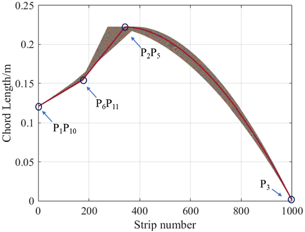
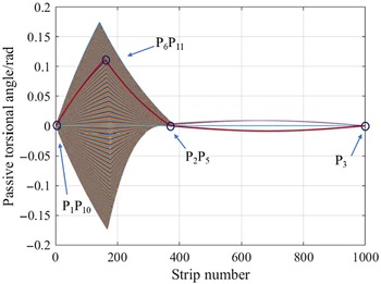
The initial parameters are used to calculate the chord length and passive torsion angle, and the curve of chord length and torsion angle in one cycle is obtained, as shown in Figs. 10 and 11. The brown area in Figs. 10 and 11 is the real-time change curve of the chord length along the span in one cycle. For the convenience of explanation, take the chord length and the passive torsion angle curve at any time for explanation, as shown in the red curve in the figure. The four points marked in the red curve correspond to the chords P 1 P 10, P 6 P 11, P 2 P 5 and the wing tip in Fig. 8. The three curves enclosed by these four points represent the chords in the three regions of the wing membrane in Fig. 8. It is easy to understand by comparing Figs. 10, 11 and Fig. 8.
Chord length change in one cycle. (The abscissa should be the span length of the membrane, but the active deformation of the wings will cause the span length to change in real time. In this paper, the BEM is used to divide the span into 1000 strips, and strip algebras are used to replace the span length).

Passive torsion angle change in one cycle.

3.1.2. Calculation of relative velocity
The relative velocity on the strip is composed of three parts: the passive torsion velocity caused by the flexible deformation of the membrane, the flapping velocity caused by the reciprocating flapping of the wing, and the freestream velocity.
The passive torsional velocity v nt(r, t) is:
 \begin{equation} v_{\textrm{nt}}\left(r,t\right)=-\frac{1}{4}c\left(r,t\right)\frac{\partial \varphi (r,t)}{\partial t}\end{equation}
The flapping velocity of the wing v pf(r, t) at the strip with the distance from flapping axis r is:
 \begin{equation}v_{\text{pf}}\left(r,t\right)=-r\frac{d}{dt}\theta _{o}\left(t\right)=-\pi fA_{f}r\cdot \cos (2\pi {ft})\end{equation}
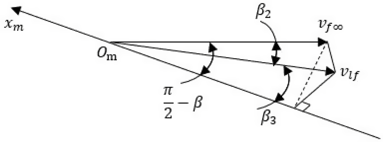
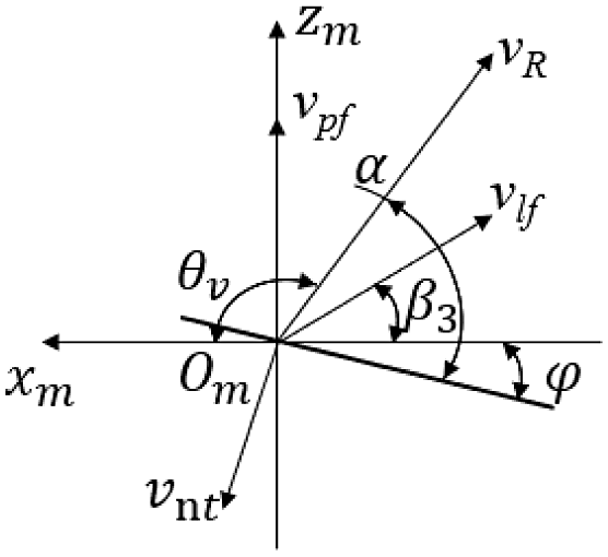
The projection velocity v lf (t) of the freestream velocity on the surface x m O m z m can be shown in Fig. 12, which can be obtained:
Projection velocity of freestream velocity.

 \begin{equation}v_{\text{lf}}\left(t\right)=v_{f\infty }\cdot \cos \beta _{2}\end{equation}
 \begin{equation}\cos \beta _{2}=\sqrt{1-\left[\sin \left(\frac{\pi }{2}-\beta \right)\sin {\theta _{o}}\right]^{2}}=\sqrt{1-\sin ^{2} \theta _{o}\cos ^{2} \beta }\end{equation}
 \begin{equation}\cos \beta _{3}=\frac{\cos \left(\frac{\pi }{2}-\beta \right)}{\cos \beta _{2}}=\frac{\sin \beta }{\cos \beta _{2}}\end{equation}
where v f∞ is freestream velocity, β 2 is the angle between freestream velocity and surface x m O m z m , θ 0 is the flapping angle, β is the angle between the flapping plane and the horizontal plane, β 3 is the angle between v lf(t) and axis O m x m .
In the plane x m O m z m , the combination of the three velocities is shown in Fig. 13:
Composite of relative velocity.

The relative velocity and the components of velocity on the xm and zm axes are shown below:
 \begin{align} \begin{cases} v_{Rx}\left(r,t\right)=-v_{\text{lf}}\cos \beta _{3}+v_{\text{nt}}\sin \varphi \\[5pt] v_{Rz}\left(r,t\right)=v_{\text{pf}}+v_{\text{lf}}\sin \beta _{3}-v_{\text{nt}}\cos \varphi \\[5pt] v_{R}\left(r,t\right)=\sqrt{v_{Rx}^{2}+v_{Rz}^{2}} \end{cases} \end{align}
3.2. Aerodynamic modeling
In this paper, assuming that the bat-like robot always flies at a constant speed and stably, the quasi-steady aerodynamics model can be used to predict the aerodynamics of the flapping membrane. What’s more, the BEM is used to strip the membrane, the unsteady flow is regarded as quasi-steady flow at each time and in each strip. Whitney and Wood [Reference Whitney and Wood23] have proved that the BEM can ensure the applicability of the quasi-steady aerodynamic model.
3.2.1. Translational circulation aerodynamic force
The translational circulation generated by the membrane consists of two parts, one is the circulation generated by the freestream flow acting on the membrane. The other part is the change of the velocity caused by the flapping of the wing, resulting in the circulation. The quasi-steady translational aerodynamic force can be obtained through the vector synthesis of lift and drag in the membrane coordinate system. The tangential component of translational aerodynamic force is very small and can be ignored. The two-dimensional quasi-steady constant lift and drag coefficient of the membrane can be given according to the empirical equation by Dickinson [Reference Dickinson24]. However, the equation summarized by Dickinson is an empirical equation based on insect experiments, and the model in this paper is a bat. Due to the large difference in size, this equation cannot be directly used to calculate the bat model, and the coefficient needs to be corrected according to the experimental data of bats. Using the data of the bat lift coefficient and drag coefficient obtained by Colorado [Reference Colorado, Barrientos, Rossi and Breuer25], the empirical equation summarized by Dickinson is modified. The revised Eqs. (25) and (26) are as follows:
 \begin{equation}C_{L}=-8.487-9.588\,\sin\, (0.0233\alpha +4.304)\end{equation}
 \begin{equation}C_{D}=0.2844+0.2262\cos\, (0.09426\alpha +3.652)\end{equation}
The lift and drag on each strip are:
 \begin{equation}dL_{\text{trans}}=\frac{1}{2}\rho v_{\text{trans}}^{2}C_{L}{cdr}\end{equation}
 \begin{equation}dD_{\text{trans}}=\frac{1}{2}\rho v_{\text{trans}}^{2}C_{D}{cdr}\end{equation}
 \begin{equation}v_{\text{trans}}=\sqrt{v_{f}^{2}+v_{\infty }^{2}}\end{equation}
 \begin{equation}\alpha _{\text{trans}}=\mathrm{a}\tan \left(\frac{v_{\infty }\cdot \sin \alpha +v_{f}}{v_{\infty }\cdot \cos \alpha }\right)\end{equation}
Aerodynamic force on each strip is:
 \begin{equation}dN_{\text{trans}}=dL_{\text{trans}}\cdot \cos \alpha _{\text{trans}}+dD_{\text{trans}}\cdot \sin \alpha _{\text{trans}}\end{equation}
3.2.2. Rotational circulation aerodynamic force
The membrane is made of flexible material. In the process of reciprocating flapping, it will be affected by aerodynamic force, which will cause passive torsion, resulting in an angular velocity along the leading edge axis. However, the translational aerodynamic model cannot capture the amount of circulation caused by the continuous change of torsional angular velocity. Especially when the area of the membrane is large and the material is soft, this rotational circulation cannot be ignored [Reference Sane and Dickinson26]. Therefore, aerodynamic force caused by the passive rotation needs to be considered. The aerodynamic force of passive rotation on any strip is:
 \begin{equation}dF_{\mathrm{rot}}=\frac{1}{2}\rho \omega _{\theta }\omega _{t}C_{r}{rc}^{2}{dr}\end{equation}
 \begin{equation}C_{r}=\pi \!\left(0.75-\hat{x}_{0}\right)\end{equation}
 \begin{equation}\omega _{\theta }=\frac{d}{dt}\theta =\pi fA_{f}\cos\!(2\pi ft)\end{equation}
 \begin{equation}\omega _{t}=\frac{d}{dt}\varphi\end{equation}
where
 $\omega$
θ
is the flapping angular velocity,
 $\omega$
t
is the passive rotation angular velocity, C
r
is the rotational circulation aerodynamic force coefficient, x
0 is the dimensionless length between the pitch axis and the leading edge axis.
3.2.3. Added-mass force
The above is to use the attachment vortex mechanism to calculate the circulation aerodynamic force (translation and rotation). But in many cases, especially when the wing is large, the non-circulation mechanism also has a great influence on the aerodynamic force. Therefore, it is necessary to consider the factors of non-circulation mechanism in aerodynamic calculation.
In aerodynamic research, non-circulation mechanism generally refers to added-mass force. The method mentioned by Wood [Reference Whitney and Wood23] is used to derive and calculate the normal added-mass force on the plane of the membrane:
 \begin{equation}dF_{\mathrm{add},N}=-m_{\mathrm{add},\mathrm{mid},N}\alpha _{N}-m_{\mathrm{add},\varphi,N}\ddot{\varphi }\end{equation}
And:
 \begin{equation}\alpha _{N}=-r\left(\ddot{\theta }+\dot{\varphi }\dot{\phi }\right)=-r\ddot{\theta }\end{equation}
 \begin{equation}m_{\mathrm{add},\mathrm{mid},N}=\frac{1}{4}\pi \rho c^{2}\end{equation}
 \begin{equation}m_{\mathrm{add},\varphi,N}=\frac{1}{4}\pi \rho c^{2}c_{\mathrm{dis}}\end{equation}
where c dis is the distance between the pitch axis and the midpoint of the strip.
So, the normal added-mass force on the plane of the membrane is:
 \begin{equation}dF_{\mathrm{add},N}=\frac{1}{4}\pi \rho c^{2}\ddot{\theta }r^{2}dr-\frac{1}{4}\pi \rho c^{2}c_{\mathrm{dis}}\ddot{\varphi }rdr\end{equation}
3.2.4. Inertia force
Some scholars have conducted experimental studies on aerodynamic forces and found that inertia force plays an important role in aerodynamic test experiments, especially in the vicinity of wing pitch inversion, where the inertial force is almost equivalent to the additional mass force [Reference Ke, Zhang, Shi and Chen27]. Therefore, it is necessary to consider the contribution of inertia force.
Because the membrane is connected to the wing skeleton and the shape is irregular, the BEM still needs to be used to calculate the inertial force on each strip. The inertial force of each chord is:
 \begin{equation}dF_{\text{inert},x}=-dm_{\text{strip}}\cdot \dot{v_{Rx}}\!\left(r,t\right)\end{equation}
 \begin{equation}dF_{\text{inert},z}=-dm_{\text{strip}}\cdot \dot{v_{Rz}}\!\left(r,t\right)\end{equation}
And:
 \begin{equation}dm_{\text{strip}}=\rho _{\mathrm{mem}}\cdot h_{\mathrm{mem}}c\!\left(r,t\right)dr\end{equation}
where dm
strip is the mass of each strip,
 $\rho$
mem is the density of the membrane, h
mem is the thickness of the membrane.
The inertial force of each chord is:
 \begin{equation}dF_{\text{inert}}=\left[dF_{\text{inert},x},0,dF_{\text{inert},z}\right]^{T}\end{equation}
 \begin{equation}dF_{\text{inert},N}=-dm_{\text{strip}}\cdot \dot{v_{R}}\left(r,t\right)\end{equation}
3.2.5. Resultant aerodynamic force
Based on the above aerodynamic forces, the resultant aerodynamic forces can be obtained as:
 \begin{equation}{dF_{\text{res}}}={{dN_{\text{trans}}}+dF_{\text{rot}}}+d{F_{\text{add},N}}+dF_{\text{inert},N}\end{equation}
The normal aerodynamic force obtained is only in the wing coordinate system, which needs to be transferred to the body coordinate system. The rotation matrix is used to transform the aerodynamic coordinate on the strip to the body coordinate system O b -x b y b z b . The rotation transformation matrix R is:
 \begin{equation}R=R\left(x,\theta _{o}\right)R\left(y,\varphi \right)=\left(\begin{array}{c@{\quad}c@{\quad}c} \cos \varphi & 0 & \sin \varphi \\[5pt] \sin \theta _{o}\sin \varphi & \cos \theta _{o} & -\sin \theta _{o}\cos \varphi \\[5pt] -\cos \theta _{o}\sin \varphi & \sin \theta _{o} & \cos \theta _{o}\cos \varphi \end{array}\right)\end{equation}
So, the aerodynamic force in the body coordinate system is:
 \begin{equation}dF_{\text{body}}=\left[\begin{array}{c} F_{\text{Drag}}\\[5pt] F_{\text{Lateral}}\\[5pt] F_{\text{Lift}} \end{array}\right]=R\cdot dF_{\mathrm{res}}\vec {k}=\left[\begin{array}{c} -\cos \theta _{o}\sin \varphi \cdot dF_{\mathrm{res}}\\[5pt] \sin \theta _{o}\cdot dF_{\mathrm{res}}\\[5pt] \cos \theta _{o}\cos \varphi \cdot dF_{\mathrm{res}} \end{array}\right]\end{equation}
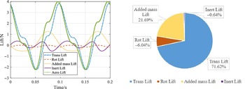
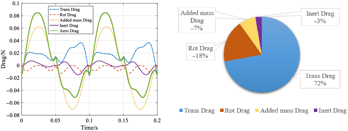
The three forces in Eq. (48) are the components of the aerodynamic force of the single wing on the x, y, and z axes, which represent drag, lateral force, and lift. The lateral force is not of great significance due to the equivalent reverse effects of the two wings. This study only considers the lift (dF Lift) and drag(dF Drag). The lift and its components obtained according to basic parameters are shown in Fig. 14. The drag and its components obtained according to basic parameters are shown in Fig. 15.
Lift and its components.

Drag and its components.

As can be seen from the Fig. 14, aerodynamic force is mostly derived from translational circulation caused by freestream flow and wing flapping. The average lift in one period accounts for 75.35%. The aerodynamic force caused by passive rotation only accounts for 14.01% of the whole, and all of them are negative lift. The added-mass force has great influence on aerodynamic force, accounting for 10.06%, and produces positive lift. However, due to the reciprocating flapping of wings, the average inert lift in one period only accounts for 0.58% of the whole, which is almost zero. It has almost no effect on the average lift, but only affects the transient lift.
As can be seen from the Fig. 15, aerodynamic force is mostly derived from translational circulation, the added-mass force and rotational circulation, while the inertia force has little influence. Among them, the translational circulation mainly affects the average drag, and at the same time, due to the existence of the translational circulation, the positive average drag will be generated. The added-mass force mainly affects the instantaneous drag, but only 7% of the average drag, and produces negative drag. The rotational circulation mainly affects the average drag, accounting for 18% of the whole, but it produces a negative average drag. However, due to the reciprocating flapping of the wing, the average drag in one cycle only accounts for 3% of the whole and has almost no influence on the average drag and instantaneous drag.
3.3. Comparison and analysis of results
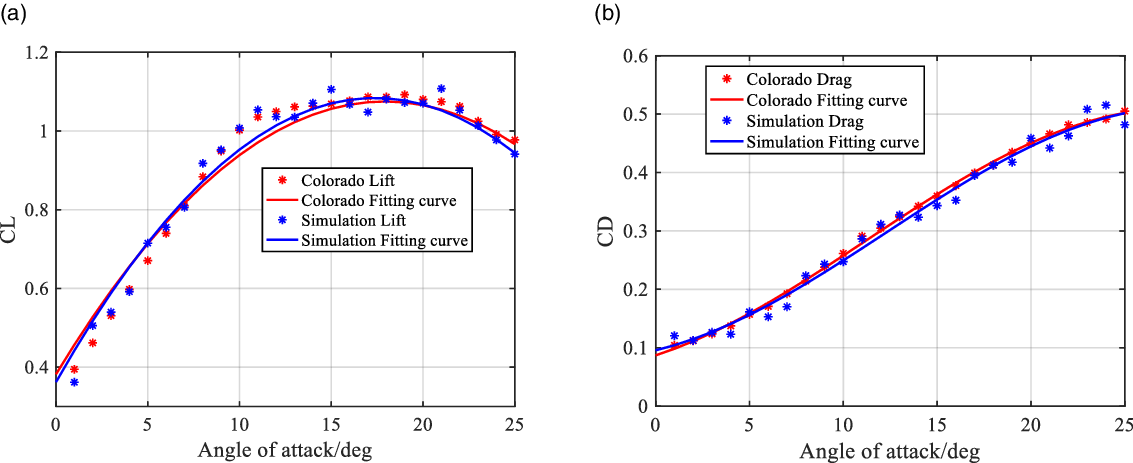
In order to verify whether the aerodynamic force calculated by the above algorithm is correct, the commercial CFD software XFlow based on the Lattice Boltzmann method is used to simulate the flow around the flapping wing. The solver can effectively deal with moving objects, and because of its automatic mesh generation (AMG) function, it can reduce the time of meshing process, improve the solving efficiency and ensure the calculation accuracy. In order to verify whether XFlow is suitable for flow field simulation of bat-like robot, this paper uses the wing model and experimental conditions in Colorado [Reference Colorado, Barrientos, Rossi and Breuer25] for simulation and compares the simulation data with the experimental data in this literature. The results of lift coefficient and drag coefficient changing with angle of attack are shown in Fig. 16. It can be seen from the curve that the simulation and experimental data are highly consistent. The average lift error of the two sets of data is 2.48%, and the average drag error is 4.68%, which can prove the accuracy of the simulation.
Comparison of aerodynamic coefficients between simulation and experiment. (a) Lift coefficient changing with angle of attack. (b) Drag coefficient changing with angle of attack.

The two membranes flap symmetrically with the same flapping rules. Without considering the coupling of the flow field, the simulation with a single wing can shorten the calculation time and improve the calculation efficiency.
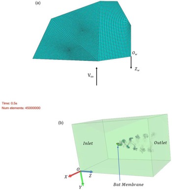
Figure 17 shows the bat membrane model and simulated wind tunnel used in this paper. The membrane material is PDMS, this material density is 1000 kg/m3, the elastic modulus is 2.3 MPa, and the Poisson’s ratio is 0.4. Abaqus is used to mesh the model. The hexahedral mesh is used for the mesh, and C3D8R is selected for the mesh element, which is used to conduct three-dimensional stress analysis of the membrane plane. In Fig. 17a, the coordinate origin O w point is set on the shoulder of the membrane, O w Z w axis is the flapping axis of the membrane, and V∞ is the freestream flow velocity of the flow field in the simulated wind tunnel. Fig. 17b is the simulated wind tunnel diagram for calculation. In order to reduce the influence of boundary conditions on the flow field, the membrane model is placed in a wind tunnel of about 10 l × 10 l × 15 l (3m × 3m × 5m), and l is the length of bat wingspan (about 0.3 m). In the flow field area, Z-axis direction is set as freestream flow velocity, X-axis and Y-axis have no flow velocity, and the outlet boundary is also the freestream outflow with velocity gradient of 0. To ensure the convergence of the results, set the Courant number to 1. The particle size in the wind tunnel is set as 0.01, and the total particle number is 45,000,000, which is enough to ensure the accuracy of calculation. The flow field medium chooses the air under normal temperature, and the other simulation conditions are set as the maximum flapping angle of the membrane is 30°, the flapping frequency is 10 Hz, the angle of attack of the membrane is 15°, and the freestream flow velocity is 5 m/s. The flapping movement and deformation movement of membrane are set according to Eq. (1) and Fig. 5 given above.
The bat membrane model and simulated wind tunnel. (a) Mesh of the membrane. (b) Simulated wind tunnel.

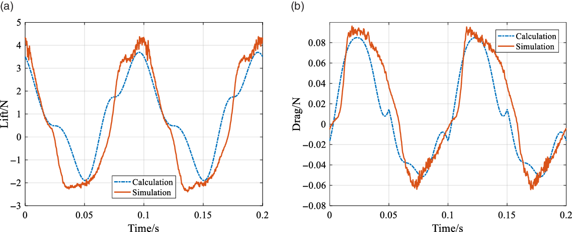
The comparison between the calculation and simulation obtained by using the above initial conditions is shown in Fig. 18.
The correctness of the theory can be verified through the analysis of Fig. 18. The theoretical calculation results are ideal and smooth, while the simulation results are more real but rough. The trends of the two are generally the same, and the curve fitting is very high. However, there are still some deviations, which are caused by the influence of unsteady effects. The theory is derived on the basis of the quasi-steady state model, ignoring the influence of unsteady, which should be the reason for the deviation of the curves. In addition, the membrane is affected by the aerodynamic force to produce elastic deformation and elastic force, and the elastic force will have a lag phenomenon relative to the aerodynamic force, so the simulation curve shows oscillation under the combined action of elastic force and aerodynamic force. From this perspective, the result curve is analyzed: firstly, in the whole movement process, the elastic deformation always exists; that is, the oscillation always exists, so the corresponding curve shows that the whole simulation curve is not smooth; when the aerodynamic force is in the maximum and minimum position, the elastic deformation of the membrane is the largest, which leads to a large change of the surface force on the membrane at this time; therefore, the oscillation of the curve is the most serious. That is the reason of the oscillation of simulation results shown in Fig. 18. From the numerical results, the maximum lift of both is around 4 N, and the maximum negative lift is around −2 N, while the maximum drag of both is around 0.08 N, and the maximum negative drag is around −0.06 N, the peak values of curves of both are almost the same. The average lift calculated by theory is 0.8997 N, and the average lift obtained by simulation is 0.9236 N. The error between the two is 2.59%, within an acceptable range. The average drag calculated by theory is 0.0402 N, and the average drag obtained by simulation is 0.042 N. The error between the two is 4.29%, within an acceptable range. From what has been discussed above, the theoretical calculation can be considered accurate.
The comparison between the calculation and simulation (a) Lift. (b) Drag.

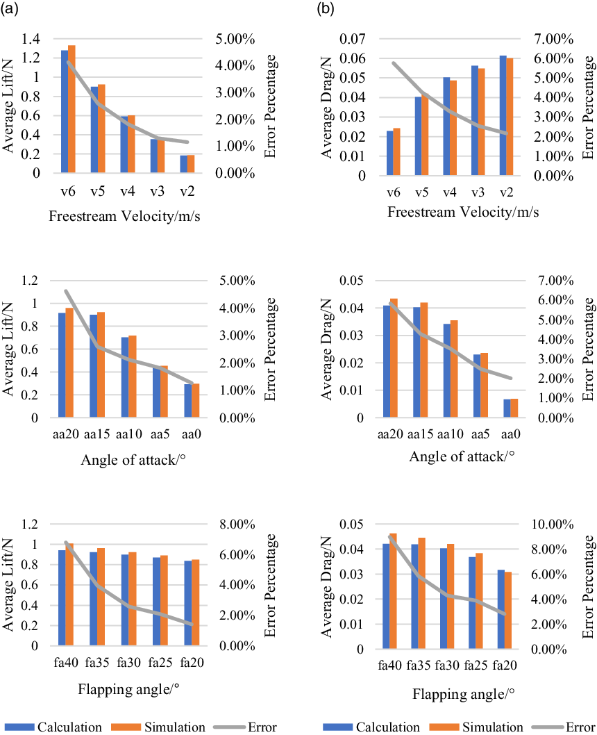
The average error of a single working condition is insufficient to show the stability of the algorithm. The average aerodynamic error of each working condition will be calculated by changing different parameters below. Compare the average lift and drag error under the conditions such as flapping angle 40°, 35°, 30°, 25°, 20°, freestream flow velocity 6 m/s, 5 m/s, 4 m/s, 3 m/s, 2 m/s, angle of attack 20°, 15°, 10°, 5°, 0°, etc. As shown in Fig. 19, the trend of the curve is similar to Fig. 18, so we will not draw them individually and only compare the error diagram.
In Fig. 19, the blue bar represents the average aerodynamic force under each working condition of theoretical calculation, the orange bar represents the average aerodynamic force under each working condition of experimental simulation, and the gray line represents the error between theoretical calculation and simulation. It can be seen from the bar chart that the freestream flow velocity and the angle of attack have a greater influence on the average aerodynamic force, while the flapping angle has a little effect on the average aerodynamic force. This is because both the freestream flow velocity and the angle of attack will directly affect the amount of translational circulation and have a monotonous effect on the aerodynamic force within a cycle. As for the flapping angle, due to the reciprocating flapping of the membrane, the effect is also reciprocating, and the positive and negative are almost offset each other, so the influence on the average aerodynamic force is small. It can be seen from the line chart that the average aerodynamic force error under each working condition is very small, the smallest lift error is only 1.15%, and the largest lift error is only 6.80%, the smallest drag error is only 2.01%, and the largest drag error is only 8.97%, within an acceptable range. It is enough to prove the accuracy and stability of the theoretical calculation. In addition, a phenomenon can be observed from the graph: With the decrease of freestream flow velocity, angle of attack and flapping angle, the error also decreases rapidly. This is because with the decrease of these parameters, the unsteady effect of flow field weakens, so the theoretical calculation results are closer to the simulation results, the error decreases rapidly, which also verifies the correctness of the theoretical model.
The error of average aerodynamic force in theoretical calculation and experimental simulation under each working condition. (a) The error of average lift. (b) The error of average drag (The abscissa of the figure: "v6" represent the freestream flow velocity of 6 m/s; "aa20" represent working conditions with angle of attack of 20°; "fa40" represent working conditions with flapping angle of 40°).

4. Conclusion
Taking the bat-like robot as the research object, and according to the aerodynamic characteristics of bat wings in flight, this paper establishes a set of calculation methods for the aerodynamic force of deformable wing membrane, which successfully realizes the aerodynamic calculation of membrane including active deformation and flexible deformation, and solves the problem of imperfect aerodynamic theoretical calculation for bat-like robot. For the first time, the equation of chord length and passive torsion angle caused by the folding and unfolding of wing and the flexible deformation of membrane is obtained, and the corresponding curve is given. Based on the quasi-steady state model and BEM, the aerodynamic force generated by the combined action of the translational circulation, the rotational circulation, the added-mass force and the inertial force is calculated. In addition, the influence of these dynamic models on aerodynamic force is analyzed, and the variation curves of aerodynamic force and its components are given.
In order to verify the correctness of the proposed theory, the aerodynamic results obtained by FSI simulation are compared with those obtained by theoretical calculation. It is found that the aerodynamic force curves obtained by the two are in good agreement, and the average aerodynamic force is almost the same, which proves the effectiveness of the proposed method. What’s more, when analyzing the error curves, it is concluded that as the unsteady effect weakened, the theoretical and simulation errors became smaller and smaller, thus verifying the accuracy and stability of the theoretical method. The research in this paper solves the problem of incomplete aerodynamic theory calculation of bat-like robot and establishes the theoretical basis for the structure optimization design and control of bat-like robot.
Future work
In the future, we will build a prototype and an experimental platform and use the experimental results to verify and analyze the theoretical calculation method. Based on the calculation method in this paper, we will analyze the influence of different factors including active deformation and flexible deformation on aerodynamics. Finally, the algorithm in this paper is applied to the structure optimization design and control of the bat-like robot.
Authors’ contributions
Hong Liu, Chuangqiang Guo and Bosong Duan conceived and designed the study. Bosong Duan designed the algorithm. Bosong Duan completed the simulation work. Bosong Duan performed statistical analyses. Hong Liu, Chuangqiang Guo and Bosong Duan wrote the paper. Chuangqiang Guo revised the paper. Hong Liu led the project reviewed work progress.
Financial support
This work is supported by the Foundation for Innovative Research Groups of the National Natural Science Foundation of China (No. 51521003), Heilongjiang Province Postdoctoral Research Startup Fund (No. LBH-Q18059).
Conflicts of interest
The authors declare that they have no known competing financial interests or personal relationships that could have appeared to influence the work reported in this paper.