Introduction
Halloysite is an aluminosilicate clay mineral, commonly formed in rocks and weathered soils worldwide (Joussein et al., Reference Joussein, Petit, Churchman, Theng, Righi and Delvaux2005) with the ideal unit formula Al2Si2O5OH4.nH2O (n=0–2). Halloysite is a nanosized clay that ranges between 40 and 12,700 nm in length with diameters of between 20 and 600 nm (Hillier et al., Reference Hillier, Brydson, Delbos, Fraser, Gray, Pendlowski, Phillips, Robertson and Wilson2016). This nanomaterial occurs naturally in a variety of morphologies, namely platy, spheroidal, and as nanotubes, with halloysite nanotubes (HNTs) being the most common (Joussein et al., Reference Joussein, Petit, Churchman, Theng, Righi and Delvaux2005). Scientific and technological interest (Atyaksheva and Kasyanov, Reference Atyaksheva and Kasyanov2021; Boraei et al., Reference Boraei, Eshghabadi, Hosseinpour, Zare, Munir and Rhee2024; Calvino et al., Reference Calvino, Lisuzzo, Cavallaro, Lazzara, Yadav, Dolgan and Lvov2025; Danyliuk et al., Reference Danyliuk, Tomaszewska and Tatarchuk2020; dos Santos et al., Reference dos Santos, Rozynek, Hansen, Hartmann-Petersen, Klitgaard, Løbner-Olesen, Michels, Mikkelsen, Plivelic, Bordallo and Fossum2017; Lin et al., Reference Lin, Wang, Liu and Miller2017; Mazloumi et al., Reference Mazloumi, Biabanpour and Nojavan2025; Wang et al., Reference Wang, Zhu, Hu, Zhang and Zhang2023; Yuan et al., Reference Yuan, Tan and Annabi-Bergaya2015) in HNTs has increased significantly in recent years, due primarily to their attractive physical and chemical properties such as nanotubular shape, high-aspect ratio, nanoscale hollow central lumina with openings at both ends of the tubes, high length-to-diameter ratio and low toxicity (dos Santos et al., Reference dos Santos, Rozynek, Hansen, Hartmann-Petersen, Klitgaard, Løbner-Olesen, Michels, Mikkelsen, Plivelic, Bordallo and Fossum2017; Vergaro et al., Reference Vergaro, Abdullayev, Lvov, Zeitoun, Cingolani, Rinaldi and Leporatti2010). Furthermore, the presence of aluminol surfaces in the inner layer and hollow cores of the nanotubes and external siloxane sheets results in contrasting positively charged hollow central lumina and negatively charged external surfaces (Massaro et al., Reference Massaro, Lazzara, Milioto, Noto and Riela2017). Such unique properties allow selective modification and result in the use of HNTs and HNT nanocomposites for the controlled release of functional compounds (Lvov et al., Reference Lvov, Wang, Zhang and Fakhrullin2016) with potential applications in bionanocomposites (Bertolino et al., Reference Bertolino, Cavallaro, Milioto and Lazzara2020) and drug delivery (Melnyk et al., Reference Melnyk, Lazzara and Chyhyrynets2025; Sharifzadeh et al., Reference Sharifzadeh, Wahit, Soheilmoghaddam, Whye and Pasbakhsh2016).
Looking specifically at the polygonal prismatic or cylindrical morphologies (Hillier et al., Reference Hillier, Brydson, Delbos, Fraser, Gray, Pendlowski, Phillips, Robertson and Wilson2016), cylindrical HNTs are characterized by their smaller particle size, in both length and diameter, with curved external surfaces, whilst their polygonal prismatic counterparts are larger in size with planar external surfaces. Recent work has shown that, in contrast to the simplistic model of halloysite nanotubes typically presented, multiple additional edge sites are present due to an abundance of steps and edges on the external siloxane surface (Gray-Wannell et al., Reference Gray-Wannell, Cubillas, Aslam, Holliman, Greenwell, Brydson, Delbos, Strachan, Fuller and Hillier2023). This is most noted in nanotubes with a polygonal prismatic tubular morphology. A previous study of phosphate sorption by cylindrical and polygonal HNTs (Gray-Wannell et al., Reference Gray-Wannell, Holliman, Greenwell, Delbos and Hillier2020) reported that, when normalized for surface area, the smaller cylindrical HNTs show greater sorption capacity than the prismatic HNTs, although direct observation of the sorption sites on the HNTs (e.g. by spectroscopic methods) was not conclusive due to the low sorption thresholds. The approach reported here, using phosphonate-functionalized metal nanoparticles such as Au and Ag, suggests that the phosphonate-terminated chains will adsorb to the halloysite surfaces in the same sites as phosphate anions (PO43–) (Gray-Wannell et al., Reference Gray-Wannell, Holliman, Greenwell, Delbos and Hillier2020). This approach enables visual detection of sorption sites on HNTs through observation of the attached Au/Ag nanoparticles via high-resolution transmission electron microscopy (TEM) imaging. Furthermore, as the potential effect of morphology has not been specified in other sorption studies using HNTs, the present study further aimed to determine whether any effect of morphology can be observed using TEM for functionalized Au/Ag-NP sorption.
In a wider context, this work has further application in that Au- and Ag-NPs are known to be thermally stable and efficient catalysts (Massaro et al., Reference Massaro, Colletti, Fiore, La Parola, Lazzara, Guernelli, Zaccheroni and Riela2019). As a result, they are frequently applied in a myriad of nanotechnologies as antibacterial (Burridge et al., Reference Burridge, Johnston and Borrmann2011; Jana et al., Reference Jana, Kondakova, Shevchenko, Sheval, Gonchar, Timoshenko and Vasiliev2017), antiviral, and anti-inflammatory agents (Zhang et al., Reference Zhang, Liu, Shen and Gurunathan2016), as well as in catalytic reactions (Mallick et al., Reference Mallick, Witcomb and Scurrell2006), as optical devices (Qu et al., Reference Qu, Du, Song, Wang, Gao, Liu, Li and Zhu2002; Rao et al., Reference Rao, Ganeev, Zhang, Fu, Boltaev, Maurya and Guo2019), and in electrochemical sensing applications (Cao et al., Reference Cao, Sun, Zhang and Jia2012). However, attractive forces between the NPs often result in the formation of clusters, which reduces their potential chemical and physical activity. This problem can be overcome by using stable support materials as anchors, reducing the required loading of these expensive metals whilst maintaining their potential chemical and physical efficiency. Selected support materials include zeolites (Riahi et al., Reference Riahi, Guillemot, Polisset-Thfoin, Khodadadi and Fraissard2002), silica (Zhang et al., Reference Zhang, Shao, Zou, Zhang, Zhang, Mu, Guo, Li, Wang and Liu2011), carbon nanotubes (Shi et al., Reference Shi, Yang and Yuet2009), and halloysite nanotubes (Burridge et al., Reference Burridge, Johnston and Borrmann2011; Jana et al., Reference Jana, Kondakova, Shevchenko, Sheval, Gonchar, Timoshenko and Vasiliev2017; Massaro et al., Reference Massaro, Colletti, Fiore, La Parola, Lazzara, Guernelli, Zaccheroni and Riela2019; Sayfutdinova et al., Reference Sayfutdinova, Cherednichenko, Bezdomnikov, Rodrigues-Filho, Vinokurov, Tuleubayev, Rimashevskiy, Kopitsyn and Novikov2023) which were the focus of the current study in terms of the fundamental aspects of their location.
In the present study, three different linker molecules were combined with Au/Ag-NPs, forming HNTs@Au-NPs/HNTs@Ag-NPs composite materials, to study HNT sorption sites by direct visualization using TEM. All three linker molecules had a thiol group at one end of an alkyl chain to bond to the Au/Ag-NPs. At the other end of the alkyl chain, two had an anionic group (carboxylate or phosphonate) to probe HNTs sorption sites and the other featured a methyl group to act as a control. Typically, when HNTs are considered for use as stable support materials they are functionalized by linker molecules prior to addition of metal nanoparticles (Kornilova et al., Reference Kornilova, Kuralbayeva, Stavitskaya, Gorbachevskii, Karpukhina, Lysenko, Pryadun, Novikov, Vasiliev and Timoshenko2021; Kumar-Krishnan et al., Reference Kumar-Krishnan, Hernandez-Rangel, Pal, Ceballos-Sanchez, Flores-Ruiz, Prokhorov, Arias de Fuentes, Esparza and Meyyappan2016; Massaro et al., Reference Massaro, Colletti, Fiore, La Parola, Lazzara, Guernelli, Zaccheroni and Riela2019; Philip et al., Reference Philip, Lihavainen, Keinänen and Pakkanen2017). In contrast, the preset study first synthesized the Au/Ag-NPs, then reacted them with the linker molecules before introducing the HNTs as stable support materials. This enabled direct visualization of surface sites and ensured that any Au/Ag observed on the surfaces of the HNTs is present from sorption of the anionic group which is pre-adsorbed to the Au/Ag nanoparticles and not due to the electrostatic interaction between the Au/Ag ions and HNT surface sites.
While previous works may have studied the sorption behaviors of Au/Ag-NPs onto HNTs (Goswami et al., Reference Goswami, Biswas, Naidu and Vasilev2019), a primary aim of the present study was to address the differences, if any, in behavior between the two tubular HNT morphologies with both Au/Ag-NPs. The present authors suggest that the carboxyl- and phosphonate-terminated chains will adsorb directly onto the surface of the HNTs at the sites identified by previous work (Gray-Wannell et al., Reference Gray-Wannell, Holliman, Greenwell, Delbos and Hillier2020) with the objective of further highlighting previous distinctions in behavior of these two morphologies (Hillier et al., Reference Hillier, Brydson, Delbos, Fraser, Gray, Pendlowski, Phillips, Robertson and Wilson2016; Gray-Wannell et al., Reference Gray-Wannell, Holliman, Greenwell, Delbos and Hillier2020).
Materials and methods
Chemicals
Dodecanethiol (methyl group, 98% purity, CAS – 112-55-0), 12-mercaptododecylphosphonic acid (phosphonic acid, 97% purity, CAS – 159239-33-5) and 11-mercaptoundecanoic acid (carboxylate, 95% purity, CAS – 71310-21-9). polyvinylpyrrolidone (CAS – 9003-39-8), and dimethylformamide (CAS – 68-12-2) were obtained from Alfa Aesar. Silver nitrate (CAS – 7761-88-8) chloro(triphenlyphosphene)gold(I) (CAS – 14243-64-2) and butyl borane (CAS – 7337-45-3) were obtained from Sigma-Aldrich.
Halloysite nanotubes
Both HNT morphologies used in this study have been well characterized previously by Hillier et al. (Reference Hillier, Brydson, Delbos, Fraser, Gray, Pendlowski, Phillips, Robertson and Wilson2016) and Gray-Wannell et al. (Reference Gray-Wannell, Cubillas, Aslam, Holliman, Greenwell, Brydson, Delbos, Strachan, Fuller and Hillier2023) where they were identified as 4Ch and 17US. In brief, the cylindrical HNTs (4Ch) are from China and have a purity of 98.5 wt.%, as determined by X-ray powder diffraction, and a specific surface area of 80.4 m2 g–1. The polygonal prismatic sample (17US) originates from the USA, has a purity of 99.0 wt.%, and specific surface area of 30 m2 g–1. X-ray diffraction patterns, infrared spectra, chemical compositions, and images from various microscopies for both samples can be found in the aforementioned publications.
Synthesis of Au-NPs
Au-NPs were synthesized as described in a previous study (Li et al., Reference Li, Liu, Yao, Sun, Jiang, Huang, Cheng, Huang, Jiang, Xie, Pan, Yan and Wei2012). For the initial Au-NP experiments on both HNT morphologies, either dodecanethiol (48 μL; 0.2 mmol) or 12-mercaptododecylphosphonic acid (0.06 g, 0.2 mmol) was added. The two flasks were then stirred for 15 min, and the contents transferred to sample vials and stoppered until ready for addition to the halloysites.
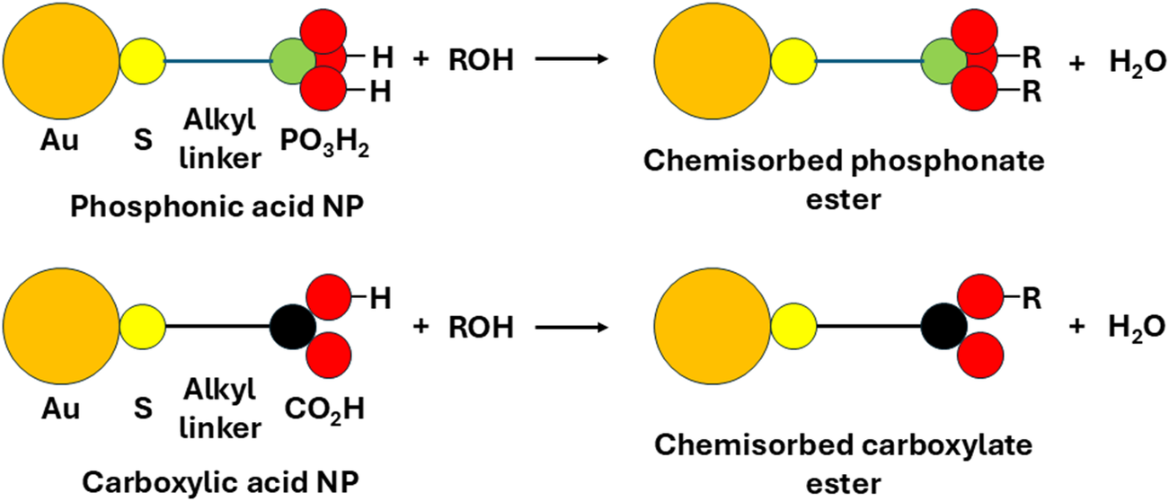
For the second experiment, on the polygonal prismatic HNTs with both phosphonic acid and carboxylate functional groups, the Au-NPs were synthesized in the same way. After the Au-NPs solution was divided between two flasks, 12-mercaptododecylphosphoric acid (0.0303 g; 1.07 mmol) was added to flask 1, while 11-mercaptoundecanoic acid (0.0224 g; 1.04 mmol) was added to flask 2. The two flasks were stirred for 15 min, and the contents transferred to sample vials and stoppered until ready for addition to the halloysites (Fig. 1).
Reaction scheme showing derivatized Au-NPs chemisorbing to halloysite surface hydroxyl groups (R = halloysite).

Synthesis of Ag-NPs
For the Ag-NP synthesis, the capping agent, polyvinylpyrrolidone (PVP, 3.44 mol), was dissolved in 200 mL of dimethylformamide (DMF) which acted as both the solvent and reducing agent (Pastoriza-Santos and Liz-Marzán, Reference Pastoriza-Santos and Liz-Marzán1999). To this solution, silver nitrate (2.5 g, 0.015 mol) was added, and the mixture was heated under reflux in an oil bath at 90°C for 6 h until the solution turned a deep yellow. The yellow color coincided with the formation of the Ag-NPs with particle size of ~5–10 nm (Van Hyning and Zukoski, Reference Van Hyning and Zukoski1998). An aliquot of 1 mL of solution was pipetted into an Eppendorf centrifuge tube and 0.2 mL of ethanol added. The samples were centrifuged for 30 s, the supernatant decanted off and replaced with a further 1 mL of ethanol. The suspension was hand shaken. The preceding stage required splitting of the solutions between two separate, round-bottomed flasks where the solution from 20 Eppendorf tubes was rinsed into each flask and were further diluted with 20 mL of ethanol. Linker molecules were added to each flask where flask 1 contained the phosphonic acid linker, 12-mercaptododecylphosphonic acid (0.0303 g, 1.07 mmol), while to flask 2 the carboxylate linker, 11-mercaptoundecanoic acid (0.0227 g, 1.04 mmol) was added. Both flasks were stirred for 15 min after the addition of the linker molecules before being stoppered.
Addition of HNTs to Au/Ag-NP solutions to form HNTs@Au-NPs/HNTs@Ag-NPs composite materials
One hundred micrograms of each halloysite was weighed out and mixed with 3 mL of nanoparticle/linker solution along with 3 mL of ethanol. Each sample was sonicated in a sonic bath at room temperature for 10 min and left to settle overnight. The following day the samples were sonicated for a further 10 min and centrifuged. All samples were dried under vacuum.
Analytical techniques
The size of the Au-NPs was measured using a Perkin Elmer Lambda 35 UV/Vis spectrometer (see Supplementary material, Fig. S1) with a scan range of 250–700 nm and after heating the UV lamps for 15 min.
Fourier transform infrared (ATR-FTIR) analysis was conducted on all vacuum-dried samples using a Bruker Vertex 70 FTIR spectrometer in the mid-infrared region from 4000 to 400 cm–1 with a scan rate of 200 scans per spectrum. The samples were dry-air purged during analysis to reduce interference from water and carbon dioxide.
X-ray photoelectron spectroscopy (XPS) analysis (using a Kratos AXIS Supra instrument with a monochromated AlKα source and a beam footprint of 700 μm on the x-axis and 300 μm on the y-axis) was used in the first set of experiments to identify the presence of phosphorus, gold, and sulfur groups on the external surfaces of the halloysites. Samples were loaded as vacuum-dried powders onto carbon strips and evacuated in situ before analysis. Survey scans at a pass energy of 160 eV were used to identify individual elements present, with a typical set of high-resolution spectra then run at a pass energy of 40 eV and step size of 0.1 eV, with a minimum dwell time of 1000 ms. Both the dwell time and the number of sweeps were increased as necessary to improve the S:N ratio for elements with small atomic concentrations. The integral charge neutralizer was used throughout and peaks were calibrated to the main hydrocarbon (contamination) peak at 284.8 eV; the data were analyzed using CASAXPS version 2.3.26PR1.0. Peak areas were estimated by applying Shirley backgrounds, except in the case of P(2p) where a negative gradient to the control background made use of a linear background more appropriate. Where peaks were fitted, the GL(30) lineshape was used. Quantification used the KratosPlus sensitivity factor library.
Simultaneous thermal analysis (STA) was conducted using a Perkin-Elmer STA 6000 instrument which had been calibrated to the melting points of indium and silver. An air-flow rate of 19.8 mL min–1 was used for a continuous run from 30 to 600°C with a 10°C min–1 ramp rate. The STA data were recorded for samples with gold nanoparticles with either phosphonic acid- or methyl-terminated linkers.
A ThermoFisher Titan Themis TEM instrument was used to record bright field images of the surfaces of the HNTs@Au-NPs and HNTs@Ag-NPs. The samples were dispersed in methanol and drop cast onto an amorphous holey carbon film mounted on a 3 mm copper grid. The TEM was operated at 300 kV and was fitted with a monochromator enabling control over the electron dose. The high sensitivity of HNTs to the electron beam resulted in a beam current of ~0.5 nA being employed. In situ EDX spectroscopy confirmed the presence of the Au/Ag-NPs and in situ SAED patterns were recorded to verify the dehydrated state of the halloysite nanotubes and the presence of gold. The EDX data were collected using a Super-X EDX system with a 4-windowless design and further processed using Velox©. Images and diffraction patterns were captured using a Gatan Oneview 16-megapixel CMOS digital camera. The TEM CMOS camera employed comprises 4k×4k pixels and the image pixel size used for sizing the nanoparticles varied between 0.0625 and 0.0450 nm, depending on the exact image magnification.
Results
Confirmation of Au-NPs on the surface of cylindrical and polygonal prismatic HNTs
The following methods: XPS, FTIR, SAED, and TEM, were used to establish the sorption of the Au-NPs via their linker molecules onto the halloysite surface of the two HNT morphologies.
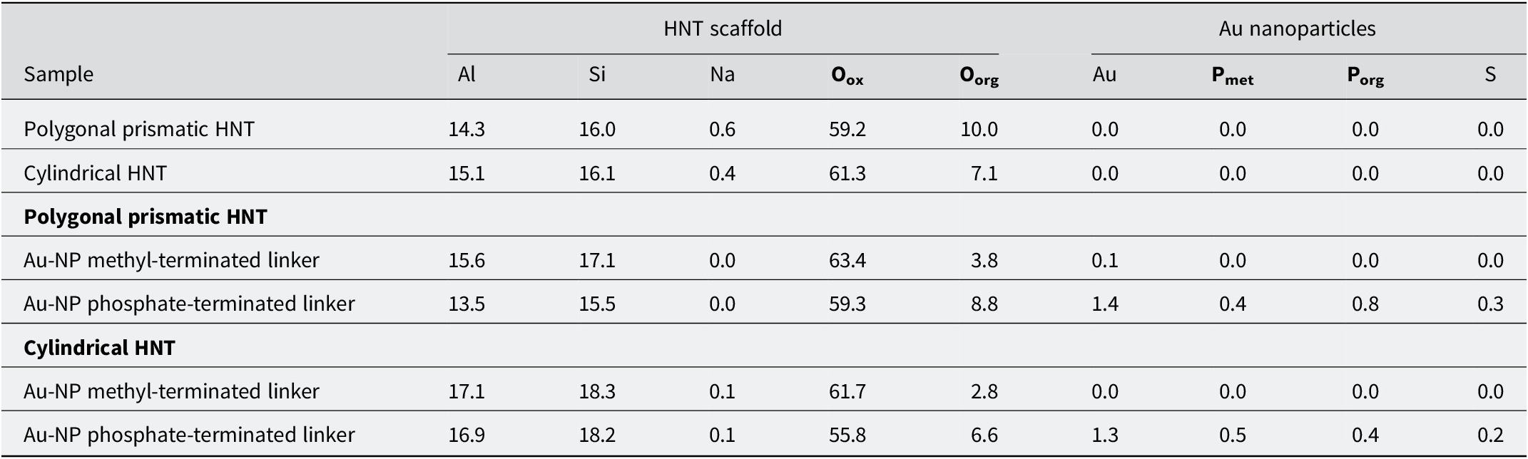
X-ray photoelectron spectroscopy (XPS) confirmed the presence of gold (1.3 at.%, 1.4 at.%), sulfur (0.2 at.%, 0.3 at.%) and phosphate groups (0.9 at.% and 1.2 at.%) on the external surfaces of both the cylindrical and polygonal prismatic nanotubes, respectively, when the Au-NPs with phosphonic acid-terminated linkers were used (Table 1; see also Table S1 and Figs S2–S9 in the Supplementary material).
XPS data (elements shown as at.% and normalized to the removal of carbon)

Table 1. Long description
The table presents atomic percent concentrations for elements normalized to the removal of carbon.
Columns are grouped into H N T scaffold (Al, Si, Na, O sub ox, O sub org) and Au nanoparticles (Au, P sub met, P sub org, S).
Row 1: Polygonal prismatic H N T contains 14.3 Al, 16.0 Si, 0.6 Na, 59.2 O sub ox, 10.0 O sub org, and 0.0 for all Au nanoparticle elements.
Row 2: Cylindrical H N T contains 15.1 Al, 16.1 Si, 0.4 Na, 61.3 O sub ox, 7.1 O sub org, and 0.0 for all Au nanoparticle elements.
Under the Polygonal prismatic H N T category:
- Au-N P methyl-terminated linker: 15.6 Al, 17.1 Si, 0.0 Na, 63.4 O sub ox, 3.8 O sub org, 0.1 Au, and 0.0 for P and S.
- Au-N P phosphate-terminated linker: 13.5 Al, 15.5 Si, 0.0 Na, 59.3 O sub ox, 8.8 O sub org, 1.4 Au, 0.4 P sub met, 0.8 P sub org, and 0.3 S.
Under the Cylindrical H N T category:
- Au-N P methyl-terminated linker: 17.1 Al, 18.3 Si, 0.1 Na, 61.7 O sub ox, 2.8 O sub org, 0.0 Au, and 0.0 for P and S.
- Au-N P phosphate-terminated linker: 16.9 Al, 18.2 Si, 0.1 Na, 55.8 O sub ox, 6.6 O sub org, 1.3 Au, 0.5 P sub met, 0.4 P sub org, and 0.2 S.
Si from SiO4 groups, Oox = metal oxide, Oorg = organic, Pmet = M-phosphonate, Porg = PX3 organic, S from thiol groups.
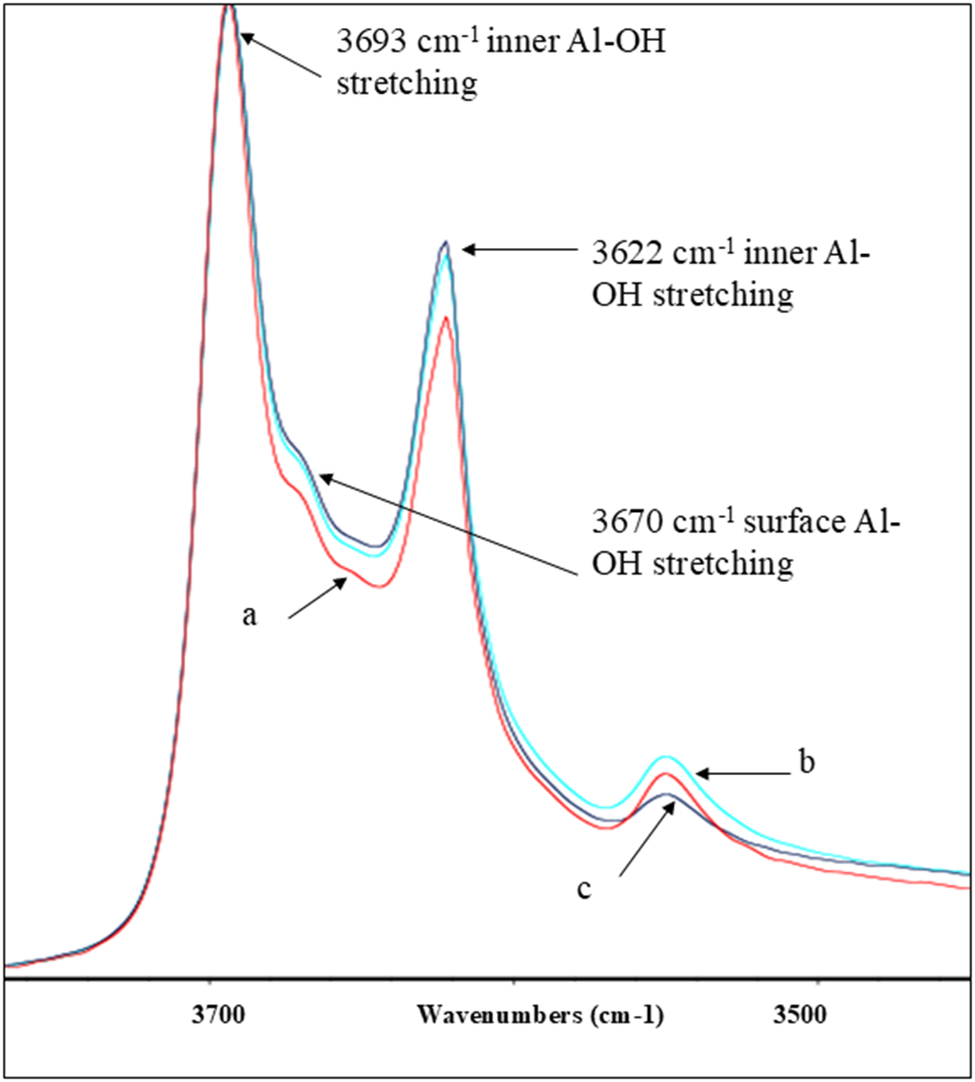
FTIR spectroscopy of the two HNT morphologies with Au-NPs derivatized either with phosphonic acid- or methyl-terminated linkers showed subtle differences in their spectra (Fig. 2; see also Fig. S10 in the Supplementary material). For the control experiment, no evidence was found of methyl-terminated linkers adsorbed to the surfaces of either cylindrical or polygonal prismatic HNTs despite this linker molecule (dodecanethiol) possessing a similar number of C–H bonds to 12-mercaptododecylphosphonic acid. This suggests that chemisorption through the phosphonate anion is the key binding mode for these linkers and that the methyl-terminated Au-NPs do not have a strong affinity for the HNTs.
FTIR spectra showing the out-of-phase stretching Al–OH bands present in the polygonal prismatic HNTs in the discrete hydroxyl region from 3400 to 3800 cm–1 of: (a) polygonal prismatic HNTs@Au-NPs with a phosphonic acid terminated linker; (b) polygonal prismatic HNTs after reaction with Au-NPs and a methyl terminated linker; and (c) original polygonal prismatic HNT material.

Figure 2. Long description
The x-axis represents Wavenumbers in cm minus 1, decreasing from 3800 on the left to 3400 on the right. The y-axis represents intensity. Three overlapping spectral curves are shown: curve a (red), curve b (light blue), and curve c (dark blue).
Moving from left to right along the x-axis:
* The first and highest peak occurs at 3693 cm minus 1, labeled as inner Al hyphen O H stretching. All three curves are closely aligned here.
* A small shoulder on the right side of the first peak is labeled at 3670 cm minus 1 as surface Al hyphen O H stretching. Curve a is slightly lower than b and c.
* The second major peak occurs at 3622 cm minus 1, labeled as inner Al hyphen O H stretching. Curve b is the highest, followed by c, with curve a being the lowest.
* A third, much smaller peak appears near 3550 cm minus 1. Here, curve b is the highest, followed by a, with curve c being the lowest.
Simultaneous thermal analysis (STA) simultaneously measures thermogravimetry (TGA) and differential scanning calorimetry (DSC). The TGA analysis of the polygonal prismatic HNT with Au-NPs and methyl terminated linkers (Fig. S11 in the Supplementary material) showed a smaller mass loss (15.0%) while the polygonal prismatic HNT sample with Au-NPs and phosphonic acid-terminated linkers (Fig. S12) showed a 17.0% mass loss. Given the XPS data which indicated that only the phosphoric acid-terminated Au-NPs sorb onto halloysite, this suggests that 2.0% of the total sample mass can be attributed to the Au-NPs with the phosphate linker as the composite material HNTs@Au-NPs formed.
In line with this, the TGA data indicated that the cylindrical sample HNT with Au-NPs and methyl-terminated linker showed a lower mass loss of 15.5% over the same temperature range (Fig. S13 in the Supplementary material), whilst the sample cylindrical HNTs with Au-NPs and phosphonic acid terminated linker (Fig. S14) showed an 18.0% mass loss over the temperature range 30–800°C. Again, considering the XPS data, where it appeared that only the Au-NPs with phosphonic acid-terminated linkers sorb onto the external halloysite surface, this suggests that 2.5% of the sample mass of the phosphonic acid-terminated linker sample can be attributed to the Au-NPs and linker.
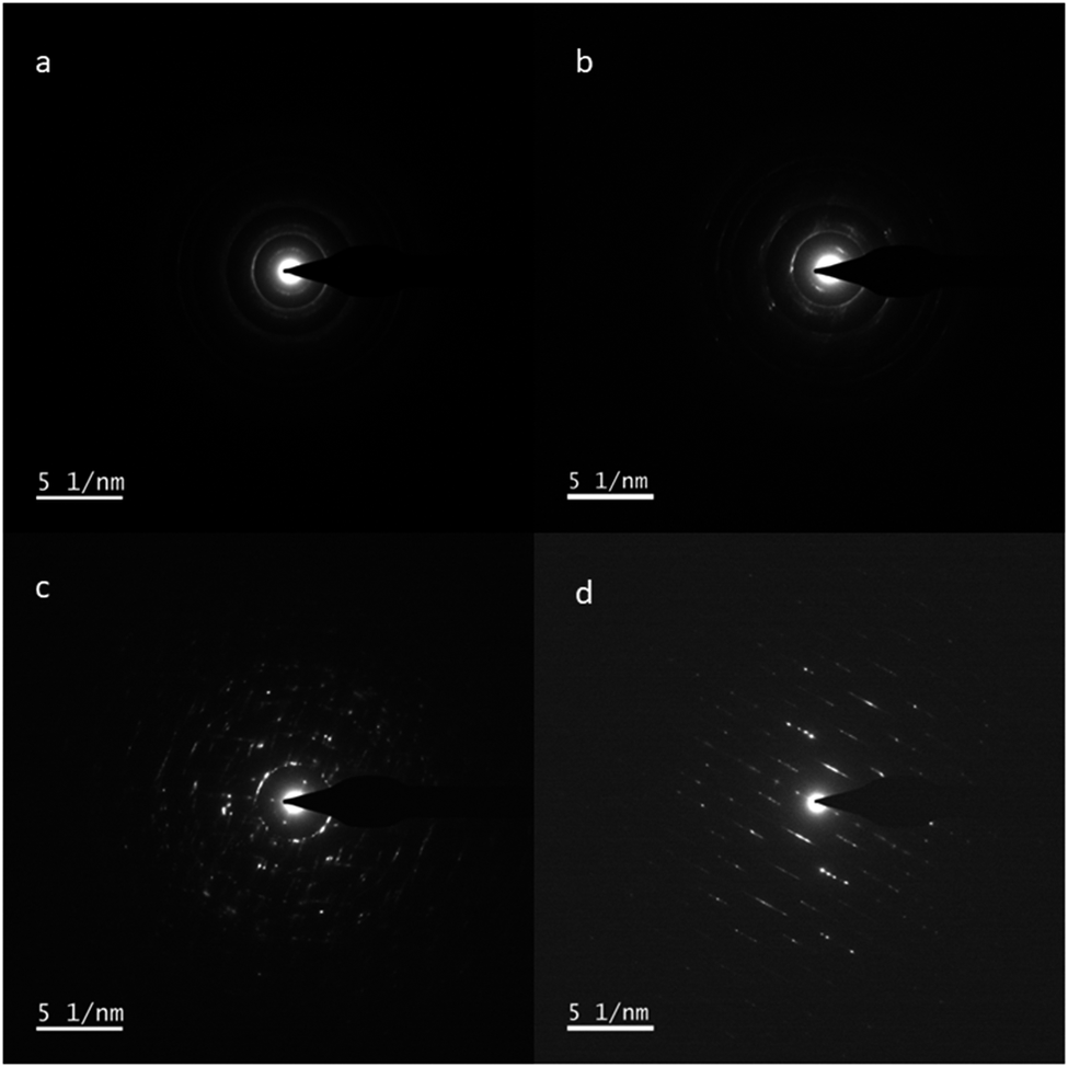
The TEM and SAED were conducted on both the untreated nanotubes and those reacted with the Au-phosphonic-acid moiety (Fig. 3). The presence of gold was confirmed from the d spacings measured at 1.2 and 0.9 Å in Fig. 3b,d; see also Table S2 in the Supplementary material).
SAED images for: (a) cylindrical HNT; (b) cylindrical HNTs@Au-NPs; (c) prismatic HNT; and (d) prismatic HNTs@Au-NPs.

Figure 3. Long description
A four-panel S A E D display with a scale bar of 5 nanometers in the bottom-left of each panel.
Panel a, top-left, shows cylindrical H N T with a central bright spot and faint concentric rings indicating a polycrystalline structure.
Panel b, top-right, shows cylindrical H N T s at A u N P s with similar concentric rings but with increased brightness and distinct spots within the rings, suggesting the presence of crystalline gold nanoparticles.
Panel c, bottom-left, shows prismatic H N T with a central spot surrounded by a more complex array of discrete diffraction spots arranged in a circular but more defined pattern than the cylindrical samples.
Panel d, bottom-right, shows prismatic H N T s at A u N P s featuring a highly ordered array of bright diffraction spots aligned in parallel diagonal rows, indicating a high degree of crystallinity and orientation in the prismatic structure with gold nanoparticles.
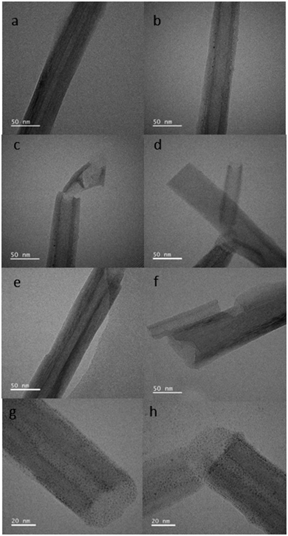
Imaging by TEM was employed to visualize the distribution of Au/Ag-NPs as they scatter electrons strongly relative to HNTs support. From the images obtained (Fig. 4; Fig. S15), the observed features on the HNTs surfaces have been confirmed as Au-NPs using in situ EDX spectroscopy (Fig. S16). Analysis of the TEM images suggested that the Au-NPs were present as spheres and ImageJ software was used to measure their size as 1.88±1.00 nm (n=819). The average size of the Au-NPs was confirmed using UV-vis spectroscopy which measured the Au-NPs size as between 1 and 2 nm (Fig. S1).
TEM images of the cylindrical and polygonal prismatic halloysite nanotubes in their untreated form and after treatment with Au-NPs and a phosphonic acid terminated linker: (a) cylindrical HNT before treatment; (b–d) cylindrical HNTs@Au-NPs; (e) polygonal HNT before treatment; (f–h) polygonal HNTs@Au-NPs.

Figure 4. Long description
The eight panels are arranged in a two-column by four-row grid. Each panel includes a scale bar in the bottom-left corner.
* Panel a: A cylindrical H N T with a smooth, multi-layered wall and a clear central lumen. Scale bar is 50 nm.
* Panel b: A cylindrical H N T decorated with small, dark, spherical A u-N P s along its outer surface. Scale bar is 50 nm.
* Panel c: A broken cylindrical H N T showing a fractured end and scattered A u-N P s. Scale bar is 50 nm.
* Panel d: Two intersecting cylindrical H N T s with visible A u-N P s on the surface. Scale bar is 50 nm.
* Panel e: A polygonal H N T showing a more rigid, angular wall structure compared to the cylindrical versions. Scale bar is 50 nm.
* Panel f: A polygonal H N T after treatment, showing a jagged edge and surface-bound A u-N P s. Scale bar is 50 nm.
* Panel g: A high-magnification view of a polygonal H N T heavily coated with a dense distribution of dark A u-N P s. Scale bar is 20 nm.
* Panel h: Two polygonal H N T s meeting at an angle, both showing high-density A u-N P coverage on their surfaces. Scale bar is 20 nm.
Given the greater visibility of Au-NPs on the polygonal prismatic HNTs it was considered that the subsequent experiments should focus on this morphology only and expand on the NPs and linker molecules studied. Hence, TEM and FTIR analysis was conducted on a further set of polygonal prismatic HNTS which had been treated with Au-NPs and Ag-NPs with both phosphonic acid- and carboxylate-terminated linkers.
Comparison of phosphonic- and carboxylate-terminated linker sorption on polygonal prismatic HNTs using both Au- and Ag-NPs
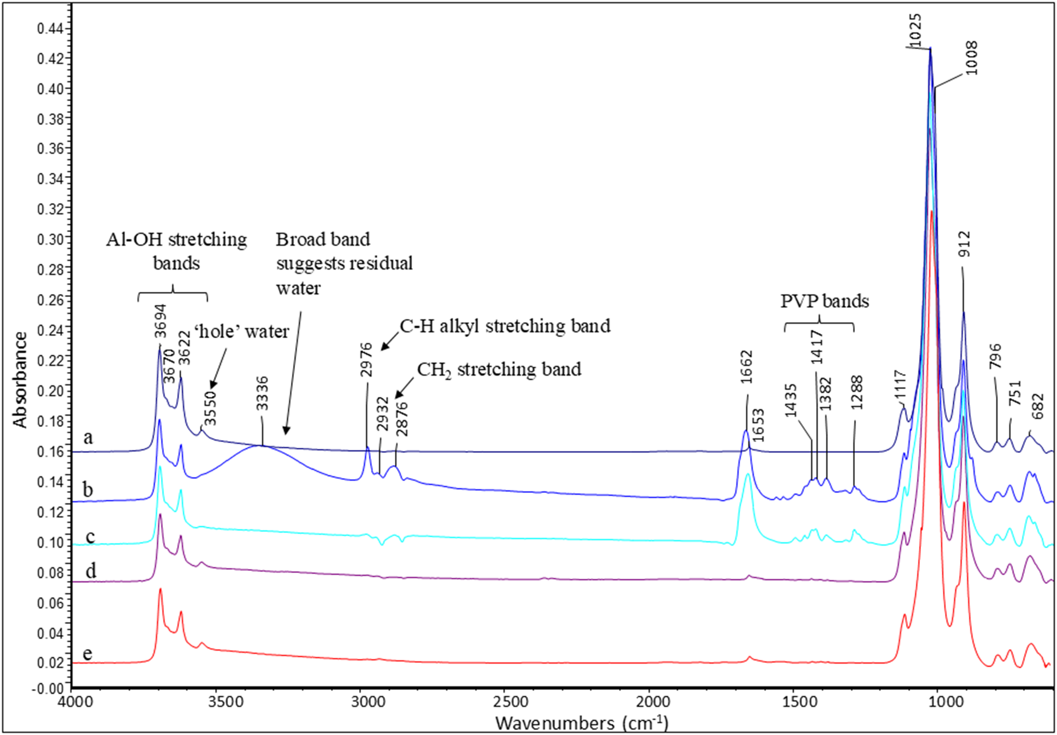
The presence of polyvinylpyrrolidone in the Ag-NP spectra (Huang et al., Reference Huang, Lin, Li, Hu and Chiu2019) with a C=O band at ~1662 cm–1, C–N bands between 1288 and 1435 cm–1, and a broad N-H peak at ~3336 cm–1 (Fig. 5b,c) all indicated the presence of the Ag-NPs. The FTIR analysis of the samples with phosphonic acid- or carboxylate-terminated linkers on polygonal prismatic HNTs again showed evidence of chemisorption via phosphonate or carboxylate esters, respectively. For example, after Au-NPs sorption, a reduction in intensity of up to 50% was calculated for the 3670 cm–1 Al–OH stretching band (Fig. 5d,e), indicating sorption at these sites. For the Ag-NPs with both carboxylate and phosphonic acid-terminated linkers the peak at 3670 cm–1 was indistinct and therefore impossible to measure.
FTIR spectra of polygonal prismatic halloysite with and without Au/Ag-NPs: (a) original material; (b) HNTs@Ag-NPs with a carboxylate terminated linker; (c) HNTs@Ag-NPs with a phosphonic acid terminated linker; (d) HNTs@Au-NPs with a carboxylate terminated linker; and (e) HNTs@Au-NPs with a phosphonic acid-terminated linker.

Figure 5. Long description
The line graph plots Absorbance on the y-axis (ranging from -0.00 to 0.44) against Wavenumbers in inverse centimeters on the x-axis (ranging from 4000 to 500). Five spectra are stacked vertically, labeled a, b, c, d, and e from top to bottom.
Spectrum a (original material) shows distinct sharp peaks at the left (high wavenumber) region: Al-O H stretching bands at 3694, 3670, and 3622. A small peak at 3550 is labeled ‘hole’ water. A broad band centered around 3336 suggests residual water. Moving right, sharp peaks at 2976, 2932, and 2876 are identified as C-H alkyl and C H sub 2 stretching bands. In the fingerprint region to the right, P V P bands are marked at 1435, 1417, 1382, and 1288. The highest intensity peaks occur at 1025 and 1008, followed by smaller peaks at 912, 796, 751, and 682.
Spectra b through e show the evolution of these signatures after modification with gold or silver nanoparticles and linkers. Spectrum b (H N T s at Ag-N P s with carboxylate linker) maintains high intensity in the 1662 and 1653 region. Spectra c, d, and e show a significant reduction in the intensity of the water-related broad bands and the P V P bands compared to the top two traces, while the primary structural peaks of the halloysite at 1025 and 3694 remain consistent across all samples.
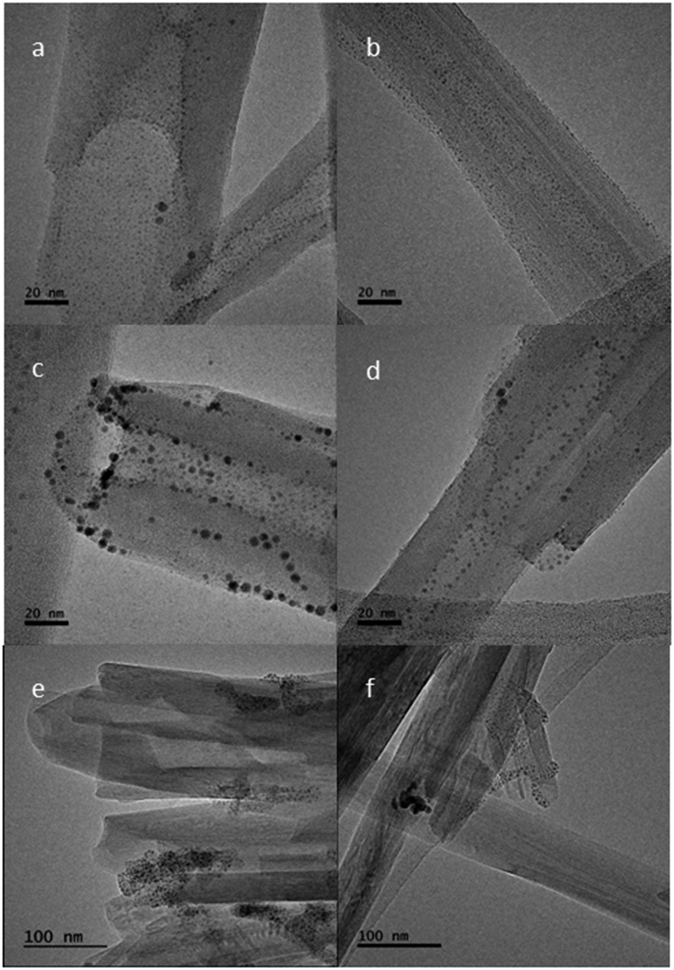
An interesting observation can be made about the different behaviors of the Au- and Ag-NPs as observed by TEM (Fig. 6), where, for the HNTs@Au-NPs, the NPs appeared clearly to adsorb onto the surface of the halloysite nanotubes at distinct sites. From Fig. 6, there is little or no visible distinction in frequency and distribution of Au-NPs when the two types of linker molecule, phosphonic acid (Fig. 6a,b) and carboxylate (Fig. 6c,d), are compared. Due to the natural variation in the sizes of Au-NPs, some of the individual HNTs showed the nanoparticles on the surface more clearly than others. This can be seen by comparing Figs 6c and 6d. The data measured using ImageJ software showed two nanotubes from the same sample but the average nanoparticle sizes in Fig. 6c are 2.66±1.03 nm (n = 99) compared with 1.71±0.60 nm (n=95) measured in Fig. 6d. The images in Fig. 7 again suggested that the aluminol sites at the termini of the nanotubes and those in the inner lumina and at steps and edges on the external surfaces are where the chemisorption occurs.
TEM images of polygonal HNT: (a,b) HNTs@Au-NPs and a phosphonic acid-terminated linker; (c,d) HNTs@Au-NPs and a carboxylate-terminated linker; (e) HNTs@Ag-NPs and a phosphonic acid-terminated linker; and (f) HNTs@Ag-NPs and a carboxylate-terminated linker.

Figure 6. Long description
A six-panel T E M micrograph series arranged in a two-column by three-row grid.
* Panel a (top-left): High-magnification view of a halloysite nanotube (H N T) with a 20 n m scale bar. Small, dark gold N P s are sparsely and uniformly distributed across the surface using a phosphonic acid linker.
* Panel b (top-right): Similar to panel a, showing a single H N T with a 20 n m scale bar and a fine, even coating of gold N P s.
* Panel c (middle-left): H N T with a 20 n m scale bar using a carboxylate linker. The gold N P s appear larger and more densely clustered, particularly along the edges and tips of the tube.
* Panel d (middle-right): Another view of carboxylate-linked gold N P s on an H N T with a 20 n m scale bar, showing irregular spacing and varying particle sizes.
* Panel e (bottom-left): Lower magnification view with a 100 n m scale bar. Multiple H N T s are visible, functionalized with silver N P s and a phosphonic acid linker. The silver particles appear as dark, concentrated clusters at specific sites rather than a uniform coating.
* Panel f (bottom-right): Lower magnification view with a 100 n m scale bar showing silver N P s and a carboxylate linker. The silver particles form dense, localized aggregates on the H N T surfaces.
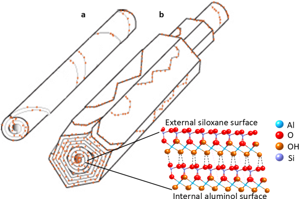
Graphical depiction of the distinction between: (a) cylindrical and (b) polygonal prismatic HNTs@Au-NPs sorption with phosphonic acid linkers, with the crystalline structure of each HNT layer indicated.

Figure 7. Long description
The diagram consists of two main structural models and a molecular legend.
Panel a, located at the top left, shows a cylindrical halloysite nanotube, or H N T, depicted as a smooth, rolled tube with orange dots representing gold nanoparticles, or A u N P s, distributed along the spiral edges of the layers.
Panel b, in the center, shows a polygonal prismatic H N T. Unlike the smooth cylinder, this structure has distinct flat faces and sharp longitudinal edges, forming a hexagonal cross-section. A u N P s are similarly distributed along the edges of the concentric polygonal layers.
In the bottom right, a detailed molecular cross-section of the H N T wall is shown. Two lines point from the layers of the polygonal tube to this detail. The top layer is labeled External siloxane surface and the bottom layer is labeled Internal aluminol surface. The molecular structure shows a lattice of atoms connected by bonds.
A legend to the right of the molecular detail identifies the atoms by color:
- Light blue sphere: A l
- Red sphere: O
- Orange sphere: O H
- Purple sphere: S i
As for the Au-NPs, the Ag-NPs are observed to be primarily spherical in shape, and their diameter was measured as an average of 3.11±1.89 nm (n=64). In contrast to the apparent individual sorption behavior displayed in the HNTs@Au-NPs composite materials with phosphonic acid- and carboxylic acid-terminated linkers, the HNTs@Ag-NPs with both phosphonic acid- and carboxylate-terminated linkers showed agglomeration. These agglomerates resulted in clusters that contain hundreds of Ag-NPs (Fig. S17 in the Supplementary material).
Discussion
In the XPS analysis, phosphorous was shown by XPS to be in two distinct chemical states in the Au-NP-treated samples: one peak was consistent with metal-phosphate, and the other with a less oxidized phosphorus which resembled a metal-coordinated PR3 organic species (Fig. S7). This could also be explained by some phosphate which has reacted, lost oxygen and formed a new chemical bond. The S 2p position matched that of an Au-S-R chemical bond. For the control experiments using methyl-terminated linker, the data showed zero or trace gold levels (0.0, 0.1 at.%) for the cylindrical and polygonal prismatic HNTs, respectively. Given that XPS sensitivity is ~0.1 at.% the gold levels on the methyl-terminated linker for the polygonal prismatic HNTs were seen as being at, or below, the limit of detection. Hence, as expected, it can be assumed that surface sorption was not occurring at a detectable level with the methyl-terminated linkers. These control experiments supported the hypothesis that only the anionic phosphate linkers can chemisorb to the halloysite surface (Fig. 1).
The subtle differences in FTIR spectra of the two HNT morphologies with Au-NPs derivatized either with phosphonic acid- or methyl-terminated linkers (Fig. 2, Fig. S10) can be explained partially because the HNTs dominated the spectra relative to the trace amounts of derivatizing linker molecules present (the Au or Ag-NPs will be IR inactive) but also, by the metal-surface selection rule, only groups where the oscillating dipole moment is perpendicular to the surface will be observed (Greenler et al., Reference Greenler, Snider, Witt and Sorbello1982). Hence, not all adsorbed bands will be observed depending on the linker-to-surface orientation which typically defaults to parallel to the surface (Le Ru et al., Reference Le Ru, Meyer, Artur, Etchegoin, Grand, Lang and Maurel2011). Bearing these factors in mind, the weak bands at ~1440 cm–1 and 2954 cm–1 were assigned as the scissoring mode of alkyl-chain CH2 groups (Yah et al., Reference Yah, Takahara and Lvov2012) and C–H alkyl stretching bands, respectively. Their presence was observed for both morphologies of HNTs@Au-NPs composites using phosphonic-acid linker molecules (Fig. S10). This was consistent with the sorption of the linker molecules (and hence the Au-NPs) on the surface of the HNTs.
The present study was able to establish that for the polygonal prismatic sample, normalization to the Si–O band height reduced the intensity of the 3670 cm–1 intermediate Al–OH stretching band by up to 50%, suggesting that chemisorption to produce phosphonate esters (Fig. 2, Fig. S10) took place at these sites. These OH-stretching bands (Fig. 2) are further explained in the polygonal morphology by out-of-phase stretching which is split due to an imperfect threefold symmetry, a phenomenon which is also observed in some kaolinites (Farmer, Reference Farmer1974; Hillier et al., Reference Hillier, Brydson, Delbos, Fraser, Gray, Pendlowski, Phillips, Robertson and Wilson2016). For the cylindrical morphology (Fig. S10), this effect was less apparent as only two O–H stretching bands are observed in this region at 3620 cm–1 and 3690 cm–1, as the cylindrical morphology is less crystalline (Hillier et al., Reference Hillier, Brydson, Delbos, Fraser, Gray, Pendlowski, Phillips, Robertson and Wilson2016). Furthermore, it was not possible to determine the linker-binding mechanism (i.e. mono- or bi-dentate) to the HNTs by FTIR. This is explained when the weak intensity of the much more prevalent C–H-related bands is considered (Fig. S10). For example, there are 24 C–H bonds to one phosphonate group in this linker molecule (12-mercaptododecylphosphonic acid) and the C–H modes are very weak. Hence, the anticipated phosphonate binding groups are below the limit of detection by FTIR. The bands observed at ~3550 cm–1 can be assigned to ‘hole’ water as discussed by Hillier et al. (Reference Hillier, Brydson, Delbos, Fraser, Gray, Pendlowski, Phillips, Robertson and Wilson2016).
The concentric rings observed in the cylindrical HNT sample by SAED can be explained by the reduced crystallographic ordering between adjacent planes of atoms due to their curved layers. By comparison, the polygonal prismatic sample is likely to show more crystallographic ordering due to the planar nature of its external layers leading to greater long-range order, in turn resulting in the spots observed in the electron diffraction patterns. Similar effects can be seen in XRD when comparing cylindrical and polygonal prismatic nanotubes (Hillier et al., Reference Hillier, Brydson, Delbos, Fraser, Gray, Pendlowski, Phillips, Robertson and Wilson2016) showing that multiple analytical methods can be employed to distinguish between the two HNT morphologies.
Comparing the TEM data for Au-NPs sorption onto the cylindrical or polygonal prismatic HNTs, the data showed that for both morphologies the HNTs@Au-NPs composites displayed Au-NPs on the surface of the internal lumina, at the tube termini and on the external surfaces of the tubes. This would appear to be in agreement with previous studies that have shown that the sorption of phosphonic acids occurs on the inner lumina of halloysites, the primary location exposing the aluminol groups (Taroni et al., Reference Taroni, Meroni, Fidecka, Maggioni, Longhi and Ardizzone2019). We can conclude, therefore, that the Au-NPs observed on the external surface may be indicative of steps and edges along the external surfaces of the HNTs. These features were reported recently using atomic force microscopy (AFM) (Gray-Wannell et al., Reference Gray-Wannell, Cubillas, Aslam, Holliman, Greenwell, Brydson, Delbos, Strachan, Fuller and Hillier2023), which demonstrated that the polygonal prismatic samples appeared to have a greater number of steps and edges, and hence edge aluminol sites, on their outer surfaces when compared with cylindrical samples. In this current study, it is also evident that the polygonal prismatic nanotubes had a greater density of Au-NPs visible on the outer nanotube surfaces and the lumina, whereas the cylindrical nanotubes were much sparser in terms of Au-NPs decoration (Fig. 4). The exceptions to this occurred when the halloysites themselves had lots of defects (Fig. 4c,d) where defects are present as fracturing of nanotubes, for example.
Previous work on solution-sorption experiments (Gray-Wannell et al., Reference Gray-Wannell, Holliman, Greenwell, Delbos and Hillier2020) revealed that when normalized to the surface area, cylindrical nanotubes had greater phosphate-sorption capacity than their polygonal prismatic counterparts due to their smaller size and hence greater surface area. The lesser extent of Au-NPs sorption observed here is probably due to the larger size of the Au-NPs relative to phosphate anions such that, on the smaller cylindrical HNTs, Au-NPs sorption results in greater steric repulsion between the Au-NPs. In turn, this led to the appearance of more Au-NPs on the larger polygonal prismatic HNTs. Given that the TEM data are qualitative as opposed to quantitative, a clear conclusion can be drawn that, when phosphonate groups are anchored to Au-NPs, the polygonal prismatic HNTs showed greater affinity for sorption than their cylindrical counterparts as depicted in Fig. 4 and, graphically, in Fig. 7.
The TEM analysis showed the difference in behavior between the Au and Ag nanoparticles, where the Ag nanoparticles in the HNTs@Ag-NPs formed agglomerates containing hundreds of NPs. There were several possible explanations for this. The first considered that the PVP/Ag ratio used in the NP-linker synthesis was too high (Wiley et al., Reference Wiley, Sun, Mayers and Xia2005). A second hypothesis considered that due to the harder Lewis acid nature of silver in comparison with gold, the Ag-NPs was more attracted to the phosphonic acid/carboxylate anions than the aluminol surface groups on the halloysite nanotubes, which resulted in agglomerates between Ag-NPs and linker molecules of nearby Ag-NPs. The third hypothesis suggested that the loading of the linker molecule may also have an effect where, after a certain loading concentration, the linker molecules began to link Ag-NPs, as opposed to adsorbing onto the halloysite surface, as demonstrated by the oxalate linkage in TiO2 nanoparticles (Charbonneau et al., Reference Charbonneau, Holliman, Davies, Watson and Worsley2015). The significance of the different behaviors of the Au- and Ag-NPs in the HNTs@Au-NPs and HNTs@Ag-NPs composites was highlighted when considering the practical applications of this type of work; further work is required to determine whether changing the experimental conditions would result in a different Ag-NPs dispersion on the HNTs surfaces, particularly by determining whether larger Ag-NPs may result in less agglomeration (Jana et al., Reference Jana, Kondakova, Shevchenko, Sheval, Gonchar, Timoshenko and Vasiliev2017).
Conclusions
The present study has presented a method for the direct observation of surface sorption sites on two different morphologies of HNTs by combining the resolving power of TEM of HNTs@Au-NPs/HNTs@Ag-NPs, which have been surface engineered, with pendant phosphonate or carboxylate linker groups to mimic phosphate or carboxylate sorption, respectively. The data show that the presence of Au-NPs on the external surfaces, inner lumen, and edge sites of the HNTs depends on the polygonal or cylindrical HNT morphology. Interestingly, polygonal prismatic HNTs, which have been shown previously to have more external surface features (Gray-Wannell et al., Reference Gray-Wannell, Cubillas, Aslam, Holliman, Greenwell, Brydson, Delbos, Strachan, Fuller and Hillier2023), displayed greater Au-NPs sorption. By comparison, the smaller cylindrical HNTs displayed less Au-NPs sorption which can be hypothesized as being due to steric effects of the Au-NPs. In the present study, for the HNTs@Ag-NPs, the Ag-NPs formed clusters/agglomerations at the surfaces of the polygonal HNTs. The data suggested that the polyvinylpyrrolidone and DMF used in the Ag-NPs synthesis complicated the interaction of the linker groups with these metal nanoparticles. The sorption of carboxylate or phosphonic acid functionalized Au-NPs, but not for the methyl-terminated linker groups, also supporting the suggestion that chemisorption was being measured via the formation of ester groups with surface hydroxyls rather than physisorption. In summary, the present work highlighted the fundamental importance of understanding the detailed effect of the morphology of the nanotube (Gray-Wannell et al., Reference Gray-Wannell, Cubillas, Aslam, Holliman, Greenwell, Brydson, Delbos, Strachan, Fuller and Hillier2023) which impacts on the efficacy of halloysite nanotubes as stable support materials for use in catalytic technologies for Au-NPs, pollutant sorption or drug delivery and/or antibacterial functions when Ag-NPs are considered.
Supplementary material
The supplementary material for this article can be found at http://doi.org/10.1017/cmn.2026.10039.
Data availability statement
All data generated or analyzed during this study are included in this published article and its supplementary information files.
Acknowledgements
None.
Author contributions
N.G.-W. – conceptualization, methodology, investigation, analysis, writing – original draft; C.K. – methodology, investigation, writing – review and editing; Z.A. – TEM investigation, writing – review and editing; J.M. – XPS investigation, writing- review and editing; S.H. – supervision, writing – review and editing; C.G. – supervision, writing – review and editing; R.B. – funding acquisition, writing – review and editing; P.J.H. – conceptualization, supervision, writing – review and editing.
Financial support
The authors acknowledge external user funding from the Sir Henry Royce Institute and the Leeds EPSRC Nanoscience and Nanotechnology User Facility (EPSRC Grant EP/R02863X/1), which allowed access to TEM facilities at the University of Leeds. N.G.-W. acknowledges the support of the Macaulay Development Trust for her PhD funding. N.G.-W. and S.H. acknowledge support from the Rural & and Environment Science & Analytical Services Division of the Scottish Government.
Competing interests
The authors declare none.