1. Introduction
Noninvasive diagnosis and treatment is a future direction of the development of human medicine. Compared with plug-in gastrointestinal endoscopies, capsule endoscopies have the greatest advantages of painlessness, noninvasion, safety and convenience, especially for the examination of small intestine. Capsule endoscopies have developed from the passive type relying on intestinal peristalsis to the self-active type (i.e., capsule robots) which is now the focus of application and research. The conventional capsule endoscopy has a smooth surface and cylindrical shape [Reference Iddan and Meron1]. In order to improve the propulsive force, staying, fixing, or sampling in the pipe, researchers have changed its shape, using threaded structures [Reference Guo, Bao and Fu2, Reference Liang, Peng and Chen3], leg or claw structures [Reference Huda, Liu and Saha4, Reference Meng, Yan and Jiang5], and wheel structures [Reference Hoang, Le and Kim6].
At present, there are many ways to drive capsule robots. One way is the internal drive way, which uses batteries or cables [Reference Mousa, Feng and Dai7, Reference Gao, Yan and Shi8], but there are some problems such as insufficient energy supply or inconvenient movement. Therefore, another widely used way is the external drive way. Among these external drive ways, the magnetic field drive way has great advantages. The magnetic field drive ways mainly consist of the coil drive way and the permanent magnet drive way. In the coil drive way, multiple groups of electrified coils (mainly Holmhertz coils) are used to produce an arbitrary magnetic field to drive the magnetic capsule to move in a pipe [Reference Son, Dong and Sitti9, Reference Yuan, Wan and Mao10]. In this way, the magnetic field is relatively uniform, but it is difficult to control the capsule robot. In the permanent magnet drive way, the magnetic capsule robot is driven to follow the motion in the pipe in the same manner as the linear or rotary motion of the external permanent magnet [Reference Li, Barjuei and Ciuti11, Reference Pittiglio, Barducci and Martin12]. This way is relatively convenient to control and operate, but it is also difficult to control the force balance and the movement suffers from a slight lag relative to the movement of the external permanent magnet.
Computational fluid dynamics (CFD) is a numerical calculation method of fluid field, which is widely used in the calculation of velocity and force of fluid machinery. Zhou et al. used CFD to calculate the influence of external thread parameters on the propulsion speed and friction torque of the spiral capsule robot driven by coils and test the propulsion speed of the capsule robot with different spiral structures [Reference Zhou, Alici and Than13]. Liang et al. used CFD to calculate the influence of environmental parameters and operating parameters on the performance of the inner spiral capsule robot with built-in micro batteries. The running feasibility of the robot in a pipe with liquid is verified by experiments [Reference Liang, Peng and Chen3]. Ye et al. used a square magnet to drive a magnetic capsule of an outer spiral structure for translational and rotational motion, and experimentally analyzed the robotic translational speed at different robotic rotational speeds under different distances between permanent magnets and capsule robots [Reference Ye, Zhang and Sun14]. Guo et al. used Hertz contact theory, finite element method, and experimental method to study the pressure of the smooth capsule robot on the pipe wall at different translational speeds [Reference Guo, Liu and Prasad15]. Wang et al. calculated and measured the fluid velocity at the pipe outlet under different thread parameters of a spiral capsule robot [Reference Wang, Guo and Fu16]. Tang et al. used CFD to calculate the force of a smooth capsule robot in pipes with different sizes and measured the fluid velocity in the pipe [Reference Tang, Liang and Xiang17].
Particle image velocimetry (PIV) is a noncontact measuring method for moving fluids [Reference Fan, Liu and Xu18-Reference Blois, Bristow and Kim19]. In addition to dispersing tracer particles into the fluid, all measurement devices do not intervene in the fluid field.
The above research shows that the scientific theories of smooth and spiral capsule robots are mostly tribological theory, fluid lubrication theory, finite element method, and CFD based on finite volume principle. Among them, tribological theory is mainly used for the contact mechanics analysis between robots and pipes. Fluid lubrication theory is suitable for the mechanical analysis of robots under a mucus film of a certain thickness. Finite element method is used for the mechanical analysis between robots and pipes when the pipe is deformed. CFD is used for the fluid flow field analysis in a pipe and the mechanical analysis of robots when a capsule robot is running in all kinds of fluid environments. Therefore, CFD has a wide range of applicability in fluid environments. The experimental research is mainly focused on the analysis of the tribological characteristics of capsule robots, the operating feasibility analysis of capsule robots, the drive analysis of an external magnetic field, and the relationship between the thread parameters and fluid characteristics and the operating speeds of capsule robots.
Aiming at the spiral capsule robot with higher propulsive force in liquid environments, we design a spiral capsule robot containing permanent magnets driven by an external permanent magnet. Using the CFD method, the fluid field (velocity, streamlines, and vorticity) in a pipe during the translational and rotational motion of the robot is analyzed. At the same time, the PIV technology is used to measure the fluid velocity and vorticity in a pipe when the spiral capsule robot is precessing, and the correctness of the CFD method is proved. The influences of the robotic translational and rotational speeds on the four evaluation indicators of the robot performance are further studied. This provides a basis for the selection of the most reasonable translational speed and rotational speed of the capsule endoscope during intestinal examination.
2. Magnetic Drive System of the Capsule Robot
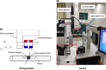
In Fig. 1(a), according to the permanent magnet drive way, a magnetic capsule robot system is designed. The external magnet is an annular cylinder, with uniform radial magnetization, one half is South Pole, and the other half is North Pole. The capsule robot is placed in a pipe. Inside the capsule robot, there is a micro inner magnet, which is a solid cylinder. The magnetization direction and the magnetic pole distribution of the inner micro magnet are the same as that of the external magnet.
Magnetic drive system of the capsule robot.

At the start, the external magnet is placed directly over the spiral capsule robot along the y axis. The spiral capsule robot is attracted by the external magnet and adhered to the upper part of pipe wall. At this time, the spiral capsule robot is in equilibrium by the gravity, mucus buoyancy, magnetic force, and contact pressure with the pipe wall. A multiaxial motion platform and a rotating motor are used to drive the external magnet to translate and rotate along the x axis. Because of its magnetic force on the micro inner magnet, the spiral capsule robot is driven to run along the x axis in the same way. At this time, the force on the spiral capsule robot in the x-axial direction includes the x-axial component of magnetic force, mucus resistance and friction with the pipe wall. Figure 1(b) is a magnetic drive system of capsule robot. The external magnet has an outer diameter of 28 mm, an inner diameter of 12 mm, and a length of 30 mm. The inner and external magnets are made of NdFeB.
3. Numerical Calculation Model and Gird
3.1. Related parameters and mathematical model
When a fluid bypasses a capsule robot, a fluid vortex will be generated in a pipe. Vorticity is usually used to measure the magnitude and direction of a vortex and is defined as the curl of the fluid velocity vector, with unit is s-1. As long as there is a vorticity source, vortices of different sizes will be produced. The vorticity is calculated as follows [Reference Li, Zhang and Zhang21].
 \begin{align}{\boldsymbol{\Omega }}=2{\bf{\omega }}{\rm{ = }}\nabla \times {\bf{u}}\end{align}
where
 ${\boldsymbol{\Omega }}$
represents vorticity;
u
represents linear velocity; and
 ${\boldsymbol{\omega }}$
represents rotational angular velocity.
Because a capsule robot makes precession motion, that is, the translation along the axial direction of a pipe and rotation around its own central axis, the fluid near the capsule robot in the pipe also has the axial motion and tangential motion that is tangent to the circumferential direction of the capsule robot, and the fluid flow is turbulent. Turbulent intensity is the most important characteristic quantity to describe the turbulent motion characteristics of fluid and is the relative index used to measure the turbulence. Turbulent intensity is usually defined as the ratio of the mean square root of the pulsating velocity to average velocity. Pulsating velocity is an instantaneous velocity at a certain point that fluctuates up and down around a certain average value. The greater the turbulent intensity of the fluid surrounding the robot is, the more disordered the relative motion of the fluid is, and the worse the stability of the robot is
 \begin{align}I = \frac{{{u_{msr}}' }}{u} = \frac{{\sqrt {\frac{1}{N}\sum\limits_{i=1}^N {{{({u_i} - u)}^2}} } }}{u}\end{align}
where I represents turbulent intensity, u
msr
 $^{\prime}$
represents mean square root of the pulsating velocity, u represents average velocity, and N represents number of sampling points in a period of time.
Supposing that a fluid is Newtonian, incompressible and ineffective for temperature, when a spiral capsule robot runs in a pipe filled with fluid, the continuity and momentum conservation equations of fluid are satisfied [Reference Wang20].
 \begin{align}\frac{\partial }{{\partial {x_i}}}(\rho {u_i})=0\quad (i=1,2,3)\end{align}
 \begin{align}\frac{{\partial (\rho {u_i})}}{{\partial t}} + \frac{{\partial (\rho {u_i}{u_j})}}{{\partial {x_j}}} = - \frac{{\partial p}}{{\partial {x_i}}} + \frac{\partial }{{\partial {x_j}}}\left(\mu \frac{{\partial {u_i}}}{{\partial {x_j}}} - \rho \overline {{u_i}^{\prime} {u_j}^{\prime} } \right) + {F_i}\end{align}
where t represents time; x i represents Cartesian coordinate; u i represents mean velocity of fluid along the x i axis; u i ’ represents pulsating velocity of fluid along the x i axis; p represents mean pressure on microelement fluid; ρ represents fluid density; μ represents fluid dynamic viscosity; and F i represents physical force on microelement fluid.
 \begin{align} - \rho \overline {{u_i}^{\prime} {u_j}^{\prime} } = {\mu _t}\left(\frac{{\partial {u_i}}}{{\partial {x_j}}} + \frac{{\partial {u_j}}}{{\partial {x_i}}}\right) - \frac{2}{3}\left(\rho k + {\mu _t}\frac{{\partial {u_i}}}{{\partial {x_i}}}\right){\delta _{ij}}\end{align}
where
 ${\delta _{ij}} = \left\{ \begin{array}{l}1\quad i = j\\0\quad i \ne j\end{array} \right.$
; μ
t
represents turbulent viscosity; k represents turbulent kinetic energy.
The turbulent dissipation rate
 ${\varepsilon}$
is introduced, and μ
t
is expressed as a function of k and
 ${\varepsilon}$
:
 \begin{align}{\mu _t} = \rho {C_\mu }\frac{{{k^2}}}{\varepsilon }\end{align}
where C μ is usually taken as 0.09.
k and
 ${\varepsilon}$
satisfy the following equations:
 \begin{align}\frac{{\partial (\rho k)}}{{\partial t}} + \frac{{\partial (\rho k{u_i})}}{{\partial {x_i}}} = \frac{\partial }{{\partial {x_j}}}\left[\left(\mu + \frac{{{\mu _t}}}{{{\sigma _k}}}\right)\frac{{\partial k}}{{\partial {x_j}}}\right] + {G_k} - \rho \varepsilon \end{align}
 \begin{align}\frac{{\partial (\rho \varepsilon )}}{{\partial t}} + \frac{{\partial (\rho \varepsilon {u_i})}}{{\partial {x_i}}} = \frac{\partial }{{\partial {x_j}}}\left[\left(\mu + \frac{{{\mu _t}}}{{{\sigma _\varepsilon }}}\right)\frac{{\partial \varepsilon }}{{\partial {x_j}}}\right] + \frac{{{C_{1\varepsilon }}\varepsilon }}{k}{G_k} - {C_{2\varepsilon }}\rho \frac{{{\varepsilon ^2}}}{k}\end{align}
where
 ${\sigma _k}$
=1.0,
 ${\sigma _\varepsilon }$
=1.3,
 ${C_{1\varepsilon }}$
=1.44,
 ${C_{2\varepsilon }}$
=1.92,
 ${G_k} = {\mu _t}\left( {\frac{{\partial {u_i}}}{{\partial {x_j}}} + \frac{{\partial {u_j}}}{{\partial {x_i}}}} \right)\frac{{\partial {u_i}}}{{\partial {x_j}}}$
.
Equations (3) to (8) are the mathematical model of a fluid in the numerical calculation. By using the CFD method to solve these equations, the fluid flow field surrounding the robot can be calculated, and the force of the fluid on the robot can be obtained. The solving process of the CFD method in this paper includes system modeling, grid division, boundary condition and parameter setting, and numerical solution.
3.2. System modeling
As shown in Fig. 2(a), the geometry model of a spiral capsule system includes a spiral capsule robot, a pipe, and a fluid. The outer diameter of a spiral capsule robot is 10 mm, the length is 18 mm, the both ends are hemispherical caps, and the middle part is a single thread structure. The thread pitch is 1.67 mm, the effective length of the thread is 5 mm, the spiral groove is semicircular, and the groove depth is 0.5 mm. The semicircular thread is adopted because there is no sharp angle at the top of the thread, which will not damage a pipe. According to the diameter sizes of human small intestine, the working pipe is designed as 18 mm in diameter and 300 mm in length. The fluid in the pipe is selected as silicone oil with the density of 800 kg/m3 and dynamic viscosity of 0.1 Pa·s, because it is similar to the intestinal mucus during the clinical examination of capsule endoscopy [Reference Liu, Han and Wu22].
Geometric model of the spiral capsule robot system.

Considering the translational and rotational motion of the spiral capsule robot, to refine the grid of the fluid zone around the capsule robot and analyze the influence of the fluid flow characteristics of this zone on the operation of the robot, a layer of wrapping fluid is added around the spiral capsule robot. As shown in Fig. 2(b), the shape of the wrapping fluid is the same as that of the capsule shell, and its thickness is 0.5 mm. In order to satisfy the numerical calculation, the distance between the wrapping fluid and the pipe wall is 0.5 mm.
3.3. Grid division
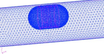
The fluid in the pipe includes two fluid zones: the wrapping fluid zone sorrounding the spiral capsule robot and the remaining fluid zone in the pipe. Unstructured tetrahedral grids are used in the two fluid zones, and dense grids are used in the wrapping fluid zone. Under the condition that the grid quality meets the requirements of the calculation, the number of grids is increased and the time step size is decreased until the numerical results tend to be stable. Figure 3 shows the turbulent intensity of the fluid surrounding the robot with the change of the grid number. When the grid number is more than 240,000, the calculation results tend to be stable. Ultimately, the grid number of the wrapping fluid zone is 18,774, the grid number of the remaining fluid zone is 234,556, that is, the total grid number is 253,330, and the time step is determined to be 0.0005 s. The grid of the fluid around the robot is shown in Fig. 4.
Grid independence analysis diagram.

Grid of the fluid around the robot.

3.4. Boundary condition and parameter setting
The standard k-
 ${\varepsilon}$
model is used for the turbulent model, and the standard wall function is chosen for the fluid flow near the wall. According to the actual situation, the robotic translational speed v is 0.02, 0.03, 0.04, 0.05 and 0.06 m/s when the robotic rotational speed n is fixed at 120 r/min. The robotic rotational speed n is 60, 90, 120, 150 and 180 r/min when the robotic translational speed v is fixed at 0.04 m/s. The gravity direction of the fluid in the pipe is along negative y axis. Because the capsule robot with embedded magnet is subject to the buoyancy of the fluid, the robot gravity, and buoyancy are offset, so the gravity of the robot is not considered. The type of solver is pressure-based, and the calculation type is transient. The scheme of pressure–velocity coupling is SIMPLE, the schemes of the pressure, turbulent kinetic energy and turbulent dissipation rate are all first order upwind schemes and that of the momentum is a second order upwind scheme. The sliding mesh and dynamic mesh are adopted to respectively simulate the rotational and translational motions of the robot, and the robot is assumed to precess along the x axis. For the dynamic mesh technology, we have compiled a user-defined function of the robotic translational velocity and set the outer surfaces of the capsule robot and the outer surfaces of the wrapping fluid zone as the dynamic mesh zones.
According to the characteristics of intestinal tracts, both ends of the pipe are treated with walls, and at first the fluid does not flow. The initial values of all zones are set to zero, and the calculated convergence precision of each variable is 0.001.
4. Experimental Measurement
4.1. Fluid measurement system of the capsule robot
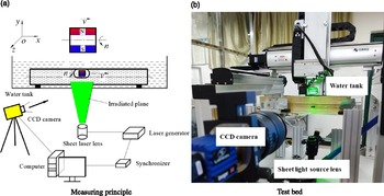
Based on the PIV technology, a fluid measurement system for the capsule robot in a pipe is designed to prove the correctness of the used CFD method. In Fig. 5(a), by the computer and synchronizer, when the CCD (charge coupled device) camera is used to take pictures, the laser generator is used to generate pulse laser synchronously. The pulse laser thickness is 1 mm, which is used to illuminate the fluid zone to be measured (the green zone in the figure, that is, the xoy plane through the center of the capsule robot when it is running), so that the CCD camera can continuously capture the image of the tracer particles in this plane. After data processing, the velocity of the fluid at the tracer particles can be obtained, that is, the velocity field at the xoy plane around the capsule robot is gotten. Light will be refracted when it propagates in two substances with large difference in density. The density difference between air and glass is larger, while the density difference between glass and water is smaller. So the test glass pipe is put into a square glass tank filled with water.
Fluid measurement system for the capsule robot.

In Fig. 5(b), based on the magnetic drive system of the capsule robot, and the fluid measurement module is added. The fluid measurement module includes a PIV system, a support, a glass tank, pressure blocks, gaskets, etc. The main components of the PIV system are the laser generator, sheet laser lens, CCD camera, synchronizer, image analysis system, computer, etc.
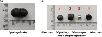
Figure 6 shows that the spiral capsule robot has an inner magnet, which is a solid cylinder with the diameter of 6 mm and the length of 5 mm. The material of the inner magnet is also NdFeB. The shell of the spiral capsule robot is black, and its composition is bioplastics. The test pipe is filled with the colorless 201 methyl silicone oil. To ensure the normal operation of the robot in the pipe, the distance between the external magnet and the spiral capsule robot remains unchanged.
Spiral capsule robot prototype.

4.2. Comparison between the numerical calculation and experimental measurement
Figure 7 shows the streamlines and velocity of the fluid around spiral capsule robot in a pipe at the xoy plane through the center of the spiral capsule robot under the robotic translational speed v of 0.04 m/s and robotic rotational speed n of 90 r/min. The zero point of the x-axial coordinate passes through the center of the spiral capsule robot, and the zero point of the y-axial coordinate passes through the bottom of the pipe. In the experiment, the pipe diameter shown is slightly larger than 18 mm, which is due to the refraction of the light irradiated to the glass pipe.
Streamlines and velocity of the fluid around the spiral capsule robot (d=18 mm, v=0.04 m/s, n=90 r/min, η=0.1 Pa·s).

The fluid streamlines around the spiral capsule robot are circular lines from the head of the robot to the end of the robot. A large fluid vortex is formed at the bottom of the robot, and the fluid velocity is higher in the middle of the region between the capsule and the pipe. The experimental results show that the overall distribution of the fluid streamlines and velocity around the spiral capsule robot is basically the same as the numerical results.
To quantitatively compare the calculated results with the measured results, as shown in Fig. 8, a rectangular coordinate system is established. The coordinate origin is the intersection of the vertical line passing through the center of the robot and the horizontal line at the bottom of the pipe. The positive direction of the x axis is horizontal to the right, and the positive direction of the y axis is vertical to the up. Fig. 9 is a comparison diagram of the CFD calculation and PIV measurement values of the fluid vorticity about z axis below the spiral capsule robot in the coordinate system shown in Fig. 8. From the bottom of the pipe upward, the vorticity of the fluid about the z axis is linearly changed from positive to negative; that is, the rotational direction of the fluid changes from counterclockwise to clockwise, and the vorticity value first decreases and then increases. When the measured results are compared with the calculated results, the minimum differences between the measured six location points are 2.5%, 0, 43.2%, 15.8%, 8.4%, and 0, respectively. In the fluid regions near the capsule robot and the pipe wall, the differences between the measured values and calculated values are smaller, indicating that the numerical results of the fluid flow field around the capsule robot are close to the experimental results. It is proved that the used CFD method is reasonable and correct.
Reference coordinate system for quantitative comparison.

Fluid vorticity about the z axis below the robot (d=18 mm, v=0.04 m/s, n=90 r/min, η=0.1 Pa·s).

5. Effect of the Operating Parameters of the Spiral Capsule Robot on Its Performance
When an external magnet translates and rotates along the x axis, a spiral capsule robot actually makes a slightly wavy precessing motion in a pipe filled with silicone oil. Through the numerical calculation, we find that the slight inclination of the spiral capsule robot has little effect on the fluid flow field. Therefore, it is assumed that the spiral capsule robot is in a horizontal state for simplification in the calculation.
For intestinal capsule robots, the translational passing ability, rotational running ability, running stability, and damage to the pipe are important factors to evaluate its performance. Their corresponding performance parameters are the forward resistance of the robot, resisting moment of the robot, fluid turbulent intensity surrounding the robot, and maximum fluid pressure to the pipe wall. The operating parameters of capsule robots are translational speed and rotational speed. Figures 10, 11, 12, and 13 show the fluid resistance to the robot in the forward direction (x axis), the resisting moment of the robot in the forward direction, the average turbulent intensity of the fluid surrounding the robot and maximum fluid pressure to the pipe wall when the robotic rotational speed n is from 60 to 180 r/min (when v = 0.04 m/s), and the robotic translational speed v is from 0.02 m/s to 0.06 m/s (when n=120 r/min).
Relationship between the resistance to the robot in the forward direction and the operating parameters of the robot.

Relationship between the resisting moment of the robot in the forward direction and the operating parameters of the robot.

Relationship between the average turbulent intensity of the fluid surrounding the robot and the operating parameters of the robot.

Relationship between the maximum fluid pressure to the pipe wall and the operating parameters of the robot.

The figures show that the resistance to the robot in the forward direction is proportional to the robotic translational speed and has almost nothing to do with the robotic rotational speed. The resisting moment of the robot in the forward direction is proportional to the robotic rotational speed and has almost nothing to do with the robotic translational speed. The average turbulent intensity of the fluid surrounding the robot and maximum fluid pressure to the pipe wall are all proportional to the robotic translational speed and rotational speed, and the influencing degree of the two operating parameters on the two performance parameters is almost the same.
In general, to improve the passing capacity of the robot, we should decrease the translational speed of the spiral capsule robot and increase the rotational speed of the robot. To reduce the energy consumption of the robot, the rotational speed of the robot can be appropriately reduced. To improve the operating stability of the robot and reduce the damage to the pipe, the translational speed and rotational speed of the robot should be reduced.
6. Conclusions and Future Work
A new type of magnetic spiral capsule robot driven by an external magnet is presented, which can translate and rotate (precess) in a pipe filled with liquid. A set of system for measuring the fluid flow characteristic in the pipe is designed and manufactured. The fluid flow information (velocity, streamlines and vorticity) in the pipe is numerically and experimentally studied. The performance parameters of the robot such as the resistance to the robot, resisting moment of the robot, average turbulent intensity of the fluid surrounding the robot, and maximum fluid pressure to the pipe wall are further calculated by the CFD method.
The velocity, streamlines, and vorticity of the fluid surrounding the robot calculated by the CFD method are basically consistent with that measured by the PIV technology. Quantitative analysis shows that the numerical results of the fluid vorticity about z axis below the robot are almost the same as the measurement results, which proves that the used CFD method is reasonable and accurate.
The further numerical calculation shows that the resistance to the robot in the forward direction is only related to the robotic translational speed. The resisting moment of the robot in the forward direction is only related to the robotic rotational speed. The average turbulent intensity of the fluid surrounding the robot and maximum fluid pressure to the pipe wall are all related to the robotic translational speed and rotational speed.
The used CFD method and PIV technology can be widely used in the calculation, measurement, and optimization for in-pipe robots in a pipe filled with fluid.
There are many factors that affect the operating performance of the spiral capsule robot, such as spiral parameters of the robot, pipe characteristics, and magnetic parameters, which will be studied in the future.
Acknowledgments
This work was supported in part by the National Natural Science Foundation of China under grant 51875051, the Natural Science Foundation of Hunan Province under grant 2021JJ30759, and the Scientific Research Fund of the Hunan Provincial Education Department under grants 19A047 and 20A043.