Introduction
In the last few decades, the accelerated use of wireless technologies in different communication systems brought attention to microstrip antennas. The different advantages of these antennas, such as the easy fabrication process, low-cost, and light-weight, made them widely used in state-of-the-art wireless communication systems. The use of multiple antennas within modern devices is not ideal owing to their tiny size. So, the ideal solution is to use a multi-band antenna to reduce the number of the needed antennas inside the compact systems [Reference Salamin, Das and Zugari1–Reference Salamin, Ali, Das and Zugari3]. Another issue related to the need for multi-band antennas is the increasing number of wireless applications. Therefore, multi-band operation is required to support various applications simultaneously. Besides, the antenna should provide an adequate operational bandwidth (BW) to fulfil the required BW of the targeted applications. Therefore, the antenna with wideband characteristics is recommended [Reference Shukla, Kashyap and Baghel4, Reference Boutejdar, Salamin, Challal, Das, El Hani, Bennani and Sarkar5]. Electrically small antennas (ESAs) gained considerable attention from researchers owing to their compact size and easy integration into different circuits. The antenna is considered to be an ESA when its size is less than one wavelength at a particular frequency [Reference Volakis, Chen and Fujimoto6]. High impedance mismatching is one of the main challenges in designing the ESAs. The induced currents on the ground (GND) plane of the ESA majorly cancel the tangential portion of alternating current on the radiator surface because these antennas have a GND close to the radiating structure. As a consequence, the BW is limited and the radiation resistance is low [Reference Sten, Hujanen and Koivisto7]. Two approaches were widely used for enhancing the impedance matching of the ESAs. The first approach is represented by the use of the matching network [Reference Sussman-Fort and Rudish8]. The second approach is represented by making different modifications to the structure of the antenna. A number of new designs for ESAs have been published recently [Reference Sohrabi, Dashti and Ahmadi-Shokouh9–Reference Salih and Sharawi14]. The metamaterial technique was used in the design process of the presented antennas in [Reference Sohrabi, Dashti and Ahmadi-Shokouh9, Reference Chaturvedi and Raghavan10]. The weakness of these antennas is the single operating band. An electric field-driven (ELC) resonator and coplanar GND plane were used in [Reference Sharma, Abdalla and Hu11] to design a compact dual-band antenna. A metamaterial-based dual-band ESA with coplanar GND was presented in [Reference Sharma, Abdalla and Chaudhary12] for wireless local area network (WLAN) and worldwide interoperability for microwave access (WiMAX) applications. The multi-layer technique was used in designing the desired antenna in [Reference Xiao, Dong, Ding and Chai13]. Several rings were printed on the antenna's different layers to enhance the impedance matching, besides generating the resonance frequencies. The designed antenna presented in [Reference Salih and Sharawi14] is a simple miniaturized patch antenna using a shorting post near the feeding location and a new defected ground structure. The designed antennas presented in [Reference Sharma, Abdalla and Hu11–Reference Salih and Sharawi14] have a relatively large size which may not be ideal for some applications where the available size is restricted.
This work is aimed at designing an ultra-compact dual-band antenna for the on-demand 3.6/5.8 GHz applications. The antenna radiating structure, which is printed on the front face of the substrate, consists of a C-shaped ring connected to a loaded U-shaped ring. A reduced GND plane is printed on the back side of the same substrate. To feed the proposed antenna, a 50 Ohm (Ω) microstrip transmission (TX) line connected to a 70.8 Ω impedance transformer has been used. In this article, the main contributions are
• Development of a new and effective dual-band ESA antenna supporting the on-demand 3.6/5.8 GHz applications with an ultra-compact size, which is one of the few ultra-compact antennas available.
• The configuration of the antenna GND plane is novel and has not been used before. In this work, we used a semi-partial GND plane. This form of the GND plane is used in the asymmetric coplanar strip-fed antennas. So, we made a hybrid configuration by using this semi-partial GND plane in a microstrip-fed antenna.
• The simplicity of the designed antenna would provide an easy integration process into practical applications.
• Considering the highly miniaturized size of the designed antenna, the achieved performance of the antenna is satisfactory. This makes the proposed antenna a suitable candidate for current and upcoming wireless applications.
The rest of this article is organized as follows: section “Antenna design” presents the design process of the proposed antenna. Section “ESA antenna limitations” presents the ESA design limitations. Section “Current distribution and CM analysis” describes the current distribution analysis combined with characteristic modes (CM) evaluation for the proposed antenna in detail. The parametric study is given in section “Parametric study”. Section “Simulation and measurement results” presents a complete evaluation of the antenna performance. Section “Comparison of the proposed design with recently published designs” summarizes a comparison of this work with recently published articles. Finally, section “Conclusion” gives the conclusion.
Antenna design
Design process
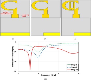
Antenna radiating structure and the GND plane, as a well-known fact, are perform an integral function in determining the antenna's end performance. Consequently, certain changes ought to be performing on the radiating structure and the GND plane to improve the overall performance of the antenna, such as enhancing the impedance BW and generating multi-resonance behavior. In an attempt to provide meaningful research, the design process is divided into three phases and the performance of the antenna in terms of the reflection coefficient is plotted for each case as shown in Fig. 1. The initial geometry of the proposed antenna is shown in Fig. 1(a). It consists of a C-shaped structure as a radiating element and an incomplete GND plane. To feed the proposed antenna, a 50 Ω microstrip TX line connected to a 70.8 Ω impedance transformer has been used. The reason for using the impedance transformer is to provide better impedance matching. The simulated reflection coefficient curve for this case is plotted in Fig. 1(d) (step I). As observed, a single resonant frequency around 4 GHz was achieved. Unfortunately, the impedance matching at this resonant is quite low. The GND plane width was reduced to improve the impedance matching as shown in Fig. 1(b). This technique is used for the first time in this work. After applying this step, the impedance matching was improved as shown in Fig. 2(d) (step II). To achieve the dual-band property, another modification in antenna structure is still required. The U-structure was used widely in antenna designs both as slots or parasitic structures to obtain single or multi-band behavior [Reference Ata, Salamin and Abusabha15, Reference Asif, Iftikhar, Rafiq, Braaten, Khan, Anagnostou and Teeslink16]. Therefore, a U-shaped structure was added to the antenna structure in this phase. The U-shaped ring was connected to the lower edge of the C-shaped structure as shown in Fig. 1(c). As a consequence, a new resonant mode is observed around 5.7 GHz as shown in Fig. 1(d) (step III). The simulated resonance frequencies are located at 3.59 and 5.72 GHz with a usable fractional BW (−10 dB) of 6.45 and 10.15%, respectively, as shown in Fig. 1(d) (step III).
Antenna evolution process and the simulated results: (a) step I, (b) step II, (c) step III, and (d) reflection coefficient curves (magnitude).

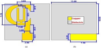
Proposed ESA final design: (a) front face and (b) back face.

The final configuration of the antenna with the detailed dimensions
Figure 2 shows the final geometry of the proposed design with the detailed dimensions in mm. Because of its low cost and being suitable for intended frequency bands with sufficient efficiency, the FR-4 laminate has been used as a dielectric material. The tangent loss and dielectric constant of this material are 0.025 and 4.4, respectively. The total dimensions of the developed antenna are 0.160λo × 0.160λo × 0.02λo.
ESA antenna limitations
The antenna is considered as a crucial part of current-day and futuristic wireless devices. Because of the ongoing miniaturization of communication devices, small and effective antennas are needed to keep up with this trend. The design of an antenna in a compact size usually results in degradation in performance, such as narrow BW, low gain, and high impedance mismatching. Consequently, certain essential requirements should be satisfied to consider the designed antenna as an ESA with an effective performance. The following subsections discuss the limitations of the ESA and highlight the effectiveness of the proposed design in terms of these limitations.
Physical dimensions
The fundamental condition to consider the antenna as electrically small was mentioned by Wheeler in 1947. The ESA is the antenna in which the greater dimension is less than λ/2π, according to Wheeler [Reference Wheeler17]. Chu [Reference Chu18] was the first who enclosed the antenna inside a sphere and wrote the fundamental bounds on the antennas in terms of the electrical length of the sphere. The commonly used definition to consider the antenna as an ESA is when ka < 1 [Reference Salih and Sharawi14] where k is the wave number (2π/λ) and a is the radius of the smallest sphere circumscribing the radiating structure of the antenna. For the proposed dual-band antenna, the calculated values of a, k, and ka at the lowest simulated resonant frequency are 7.47 mm, 75.21 rad/m, and 0.56, respectively. The computed value of ka is <1, so the proposed antenna is considered as ESA.
Radiation quality factor (Q)
The close proximity of the radiating structure of the antenna to its GND plane is the primary challenge that small antenna designers face due to the lack of available space. When the antenna's radiating portion is close to its GND, this will have a negative effect on the performance of the antenna, such as narrow BW, high impedance mismatching, and low radiation efficiency. As demonstrated in equation (1), Chu defined a relation to calculate the value of Q for the linear polarized antenna [Reference Xiao, Dong, Ding and Chai13]. The computed value of Q for the proposed antenna based on equation (1) at 3.59 GHz is 7.47.

Bandwidth
One of the essential factors in assessing the effectiveness of the antenna is BW. Due to the close space between both the radiating structure and the GND plane, the stored energy in the ESA increases, resulting in high Q values. Therefore, the BW of the ESA is limited. McLean defined a relation as described in equation (2) to compute the maximum theoretical BW of an ESA [Reference Sharma, Abdalla and Hu11]. The simulated fractional BW of the first band of the proposed dual-band antenna is 6.45%. Whereas the computed maximum theoretical BW (Q = 7.47) is 9.46%, depending on equation (2). The simulated fractional BW is approximately 3/4 of the computed maximum theoretical BW. Thus, the simulated BW of the proposed antenna is within the theoretical limits that can be accomplished.

Current distribution and CM analysis
Current analysis
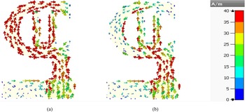
For the proposed antenna, the surface current distribution was simulated utilizing the computer simulation technology microwave studio (CST MWS) at 3.59 and 5.72 GHz as given in Fig. 3. The distributions at 3.59 and 5.72 GHz are shown in (Figs 3(a) and 3(b)), respectively. As shown in Fig. 3, the overall current is a set of currents spread along the C- and U-shapes. At a specific part of the radiating unit, the increasing of the fluctuation of the surface current belonging to the fluctuated fields which collect the charge portions sufficiently will enable the radiation of the antenna at a specific frequency. As a result of variations in current intensity along the radiating structure, multiple resonance frequencies are generated. Owing to structural modification described by the incorporation of the U-structure, a new current path was generated. The current flows in a straight line from the excitation source to the lower edge of the C-shaped structure and then the current splits into two paths as shown in Fig. 3. The current in the first path spreads across the C-shaped structure with a higher intensity and across the U-shaped structure with a lower intensity as shown in Fig. 3(a). The high-intensity, long current route helped to achieve the lower resonant mode at 3.4 GHz. For the second path, the current spread with a high intensity along the U-shaped structure, while it spreads with a lower intensity along the C-shaped structure as shown in Fig. 3(b). As a consequence of this new current path, the upper resonance at 5.72 GHz was generated. Overall, the modified geometry of the antenna provided several current paths, assisting in the achievement of multi-band functionality.
Simulated current distribution: (a) at 3.59 GHz and (b) at 5.72 GHz.

Characteristic mode analysis
The use of the theory of characteristic modes (TCM) in the design and analysis of various antennas has increased recently, owing to the physical understanding of the antenna's behavior that can be obtained without the use of any excitation source. Every CM has a characteristic angle or eigenvalue that describes the resonance and radiation behavior of this mode. According to Harrington and Mautz [Reference Harrington and Mautz19], the CM are the actual modes of a structure that are given by

where R and x are the real and imaginary parts of the Z impedance matrix, Jn represents the characteristic currents, and λn is the eigenvalue.
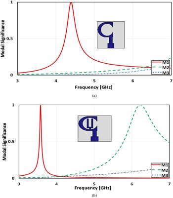
The impact of design steps on the behavior of the proposed antenna was tracked using the CM concept. The modal significance (MS), which is the normalized amplitude of the current mode, is an efficient way to describe the eigenvalue. In equation (4), the MS is defined [Reference Han and Dou20]. The MS analysis provides designers with a physical understanding of the resonance behavior of the designed antenna without the need for an excitation source. The mode can be considered as a resonance mode when its associated MS value is close to 1.

The MS curves were obtained through the use of CST MWS. The simulated MS curves for the first three modes are plotted in Fig. 4. In the absence of the U-shaped structure, it is observed that the antenna has a single mode near to 1 which is mode 1 (M1) as shown in Fig. 4(a). Therefore, M1 is a resonant mode while mode 2 (M2) and mode 3 (M3) are non-resonant modes. This explains the single resonance behavior of the antenna in this case. When the U-shaped structure was added, the simulated MS curves for the first three modes are plotted in Fig. 4(b). As observed, there are two modes having an MS near to 1 which are M1 and M2. Thus, M1 and M2 are resonant modes while M3 is a non-resonant mode. This explains that the new resonant mode (M2) was obtained after adding the U-shaped structure.
Simulated modal significance curves: (a) without U-shaped structure and (b) with U-shaped structure.

Parametric study
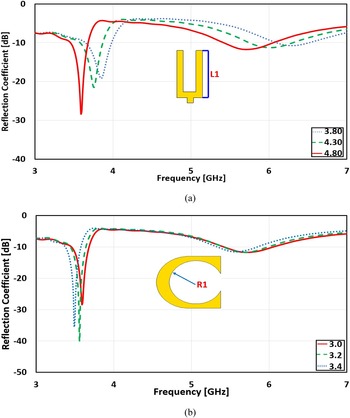
This parametric analysis is presented to provide a clear understanding of the behavior of the designed antenna based on the physical dimensions of design parameters. The impact of U-shaped and C-shaped structures on the performance of the antenna was evaluated. The CST software has been used to perform this parametric study. The simulated reflection coefficient curves corresponding to each change in the studied parameters are shown in Fig. 5.
Simulated reflection coefficient curves: (a) for various L1 and (b) for various R1.

Parameter L1
The simulated reflection coefficient curves as a function of changing L1, which is the length of the U-shaped structure, are plotted in Fig. 5(a). As observed, the parameter L1 has a major impact on BW and the locations of the resonance frequencies. Increasing the value of L1 results in a move of the resonance frequencies toward lower bands as shown in Fig. 5. On the other hand, increasing L1 results in a wider BW in the upper band and a narrower BW in the lower one. For better impedance matching, a larger L1 is preferred. The L1 value of 4.8 mm has been chosen to fit with the center frequencies of the desired applications.
Parameter R1
The simulated reflection coefficient curves as a result of varying the radius of the C-shaped structure (R1) are plotted in Fig. 5(b). It is clear that increasing R1 has a low influence on the upper band, whereas a significant impact is observed on the lower band. Increasing the value of R1 results in a move of the resonance frequencies toward lower bands. The impact of varying the value of R1 on BW is slight. The R1 value of 3.0 mm has been chosen to fit with the center frequencies of the desired applications.
Simulation and measurement results
Fabricated prototype
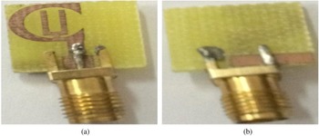
For measurement purposes, a prototype was fabricated to confirm the simulated results of the designed antenna. The in-house LPKF ProtoMat E33 machine has been used in the fabrication process. The front and back views of the fabricated prototype are shown in Fig. 6. A commercially available low-cost FR-4 laminate was used as a dielectric material with a dielectric constant of 4.4, a loss tangent of 0.025, and a thickness of 1.6 mm. The overall dimensions of the fabricated antenna are 0.160λo × 0.160λo.
Fabricated prototype: (a) front face and (b) back face.

Reflection coefficient
The reflection coefficient of the proposed antenna has been simulated utilizing the full-wave simulator CST MWS. The Rohde & Schwarz ZVB 20 vector network analyzer was used for measuring the antenna reflection coefficient. The simulated and measured reflection coefficient curves are plotted in Fig. 7. As observed in Fig. 7, the measured and simulated results are in good agreement. The slight variation between simulated and measured results can be attributed to the fabrication tolerances and faults in measurement. The simulated and measured results are tabulated in Table 1. Depending on the data listed in Table 1, the antenna has dual-band capabilities. It can be observed that the simulated fractional BW in the lower band is almost the same as the measured one, while the measured fractional BW in the upper band is degraded by 3.71% as compared to the simulated one.
Simulated and measured reflection coefficient curves (magnitude).

Comparison between simulated and measured results

Radiation patterns
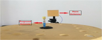
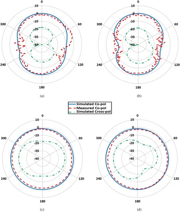
Antenna radiation is one of the important factors to be considered during the antenna design process. Geozondas far-field antenna measurement system, which is based on pulse measurement technique (Time-Domain measurements), was utilized to validate the simulated radiation patterns as shown in Fig. 8. This system works with most types of antennas and performs far-field measurements at different distances between the proposed antenna and the transmitting antenna (horn antenna). The simulated and measured two-dimensional (2D) radiation patterns of the proposed dual-band antenna are shown in Fig. 9. The radiation patterns were simulated and measured considering the two principal planes which are the E-plane (ϕ = 90) and the H-plane (ϕ = 0). The patterns were plotted at 3.62 and 5.75 GHz. Figure 9 shows a strong agreement between measured and simulated patterns. The distortion in measured patterns is attributed to the use of the Geozondas 2D far-field antenna measurement system during the measurement of radiation patterns without using an anechoic chamber, which isolates the surrounding electromagnetic effects. The antenna's radiation styles in the E-plane are almost bi-directional as shown in Figs 9(a) and 9(b). Whereas the radiation styles in the H-plane are almost omnidirectional as shown in Figs 9(c) and 9(d). Besides, the simulated 3 dB beamwidth values of E-plane at 3.62 and 5.75 GHz are 99.7 and 94.7°, respectively. The simulated sidelobe levels are −1.4 and −1.6 dB at 3.62 and 5.75 GHz, respectively. Despite the ultra-compact size of the antenna, the unique configuration of the developed antenna helped in achieving a wide 3 dB beamwidth with low sidelobe levels. This implies that from a wide range of E-plane, the antenna can detect signals. Overall, the radiation characteristics of the proposed dual-band antenna are attractive for wireless applications, thereby improves the chances of using the proposed antenna for wireless applications.
Radiation pattern measurement setup for the proposed antenna.

Simulated and measured radiation patterns: (a) E-plane at 3.62 GHz, (b) E-plane at 5.75 GHz, (c) H-plane at 3.62 GHz, and (d) H-plane at 5.75 GHz.

Gain and efficiency
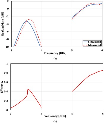
Gain and efficiency are two further factors to take into account when evaluating the antenna's performance. The gain and efficiency of the proposed antenna are plotted in Figs 10(a) and 10(b), respectively. The measured gain is well-matched with the simulated gain as shown in Fig. 10(a). As observed, the antenna had peak measured gains of −3.3 and 1.3 dBi at 3.62 and 5.75 GHz, respectively. The simulated efficiency is shown in Fig. 10(b). The maximum simulated efficiency of the antenna was 44 and 79% at 3.62 and 5.75 GHz, respectively. The lower band efficiency is lower than the upper band one as observed in Fig. 10(b). This can be explained by the direct relation between efficiency and gain. The gain value at 3.62 GHz is low compared to the value at 5.75 GHz. Therefore, the efficiency is low.
(a) Simulated and measured gain and (b) simulated efficiency.

Comparison of the proposed design with recently published designs
To emphasize the distinctiveness of the proposed antenna, Table 2 compares the features of the proposed antenna with other published works. Each design in [Reference Sohrabi, Dashti and Ahmadi-Shokouh9–Reference Salih and Sharawi14, Reference Liu and Chen21–Reference Nagar, Nagar and Meena24] was compared with our proposed design in terms of physical size, electrical size, ka factor, operating frequency, BW, realized gain, and efficiency. The data presented in Table 2 demonstrate that the proposed design has the smallest size with the exception of the design presented in [Reference Sohrabi, Dashti and Ahmadi-Shokouh9]. Besides, the designs presented in [Reference Sohrabi, Dashti and Ahmadi-Shokouh9, Reference Chaturvedi and Raghavan10] are single-band antennas. On the other hand, the calculated ka factor of the proposed design is small compared with the most papers listed in the table. According to the data presented in Table 2, the recommended antenna's performance in terms of BW, gain, and efficiency is satisfactory, considering its ultra-compact size. Therefore, the proposed antenna provided a reasonable trade-off between size and performance. This increases the chances of the proposed antenna to be used in current and future wireless applications, such as WiMAX and WLAN.
Comparison between the proposed antenna and other works

Conclusion
In this work, a new ultra-compact ESA with dual-band characteristics for 3.6 and 5.8 GHz wireless applications has been presented. The proposed dual-band antenna resonates at 3.62 and 5.75 GHz. The dual-band property was achieved in a very small footprint owing to the unique configuration of the developed antenna. Due to the use of the 70.8 Ω impedance transformer, the impedance matching of the antenna was improved. To evaluate the behavior of the designed antenna without the use of the excitation source, the TCM has been used. According to this study, two resonant modes appeared. The first and the second modes were achieved due to the use of the C-shaped structure and after adding the U-shaped structure, respectively. The total dimensions of the fabricated antenna are 0.160λo × 0.160λo × 0.02λo. Therefore, the designed antenna is one of the few available antennas that is ultra-compact in size. The antenna provides dual-band characteristics with an adequate BW, elevated gain, and high efficiency, according to simulation and measurement results. Thus, the antenna can be considered as an ideal choice for modern wireless applications.
 Mohammad Ahmad Salamin was born in Hebron, State of Palestine, in 1994. He received the B.Sc. degree in Communication and Electronics Engineering from Palestine Polytechnic University, Hebron, Palestine, in 2017. His research interests include multiple-input multiple-output (MIMO) antenna systems, millimeter-wave antennas, reconfigurable antennas, multi-band/wideband printed antennas, and other planar antennas for different wireless applications.
Asmaa Zugari received her B.S. degree in Electronic Engineering and M.S. degree in Telecommunications Systems from Abdelmalek Essaâdi University, Tetuan, Morocco, in 2002 and 2004, respectively. She received the Ph.D. degree in Telecommunications from Abdelmalek Essaâdi University, Tetuan, Morocco. The doctoral thesis was carried out as part of a collaboration between two laboratories: the Telecommunications & Information Systems Laboratory at Abdelmalek Essaâdi University and the LAPLACE Laboratory in the INPT, ENSEEIHT of the Paul Sabatier University, Toulouse, France. From 2014 to 2015, she was a Post-Doctoral in Hubert Curien Laboratory (LabHC), Jean Monnet University Saint-Etienne-France. Currently, she works as a professor in the Faculty of Sciences, Abdelmalek Essaâdi University. Her research interests include applied electromagnetism and numerical techniques for the design of microwave circuits and antennas.