I. INTRODUCTION
Waveguide filters are essential components in those communication systems requiring low loss and high power handling capability. One of the main drawbacks of waveguide structures, particularly for satellite applications, is their size and weight. The use of dual- or multi-mode filters exploiting multiple resonant modes within a single cavity is a typical solution to alleviate such problems.
One of the most common dual-mode architectures is based on circular waveguides [Reference Williams1], exploiting two degenerate TE111 modes with orthogonal polarizations. A similar concept is implemented in rectangular waveguides, with a transverse section sized in such a way as to produce degeneracy of the TE101 and TE011 modes [Reference Atia and Williams2]. Using such basic concepts several dual- and multi-mode waveguide structures have then been proposed [Reference Cameron3–Reference Lastoria, Gerini, Guglielmi and Emma5]. More recently, an all-inductive rectangular waveguide dual-mode filter class has been proposed in [Reference Guglielmi, Jarry, Keherve, Roquebrun and Schmitt6], where an oversized cavity is dimensioned so as to house a pair of degenerate modes such as TE102 and TE201, or TE102 and TE301. However, to produce mode degeneracy in rectangular waveguides, all the above-mentioned approaches require the enlargement of one cavity dimension or more, thus potentially compromising the compactness and weight of the filter.
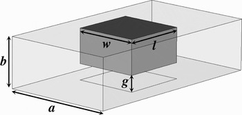
A novel class of dual-mode rectangular waveguide filters is proposed in this paper to overcome the above drawback. The key element is the square ridge resonator [Reference Bastioli, Marcaccioli and Sorrentino7]: as sketched in Fig. 1, it consists of a nearly square ridge realized within a rectangular waveguide sized to support the fundamental TE10 mode propagation. When the gap g between the ridge and the opposite waveguide wall is properly dimensioned, this kind of structure supports two modes resonating along orthogonal directions within the gap. Two resonant degenerate modes can therefore be obtained without increasing the dimensions of the rectangular waveguide. Higher-order filters can be realized by properly combining multiple square ridge resonators within compact rectangular waveguide sections.
Square ridge resonator in rectangular waveguide.

In this paper, we summarize the basic properties of the square ridge resonator proposed in [Reference Bastioli, Marcaccioli and Sorrentino7], including the unloaded Q-factor versus gap size. Several configurations are presented to produce various filtering functions, using either single or multiple coupled ridges. In particular, a novel single ridge configuration is proposed for the realization of filters with asymmetric response. A practical design procedure is presented, focusing on the control of coupling coefficients occurring between the square ridge and the rectangular waveguide fundamental mode, as well as between adjacent ridges. At the end, the experimental results of a manufactured fourth-order pseudo-elliptic filter are presented to validate the proposed approach.
II. SQUARE RIDGE RESONATOR
As is known, compared to the rectangular waveguide of the same outer dimensions, the ridge waveguide has a lower dominant mode cut-off frequency. This can be explained on the basis that the field distribution within the gap approximates that of a parallel plate waveguide; the narrower the gap, the closer the approximation.
In [Reference Bastioli, Marcaccioli and Sorrentino8] it has been verified that this behavior is maintained even when the ridge is slanting, transverse, and/or offset with respect to the waveguide central axis. This phenomenon had been exploited to design pseudo-elliptic filters based on half-wave rectangular ridges arbitrarily located within a waveguide. The term “rectangular” indicates that the ridge aspect ratio is large, i.e. the ridge width is considerably smaller than the ridge length.
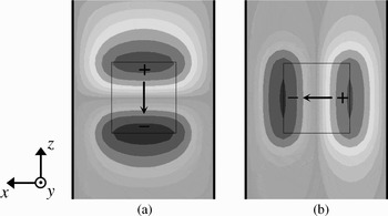
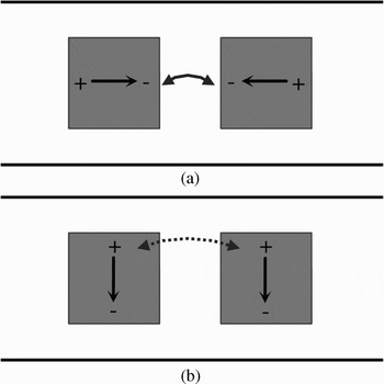
Let us now consider a nearly square ridge resonator, i.e. a ridge with almost equal width and length, realized within a rectangular waveguide working in its uni-modal frequency range. The structure is shown in Fig. 1, where g is the gap, l the ridge length, and w its width. As long as the gap g is considerably smaller than the waveguide height b, under the parallel plate approximation the ridge is expected to support two quasi-transverse electromagnetic (TEM) modes resonating along the length (longitudinal mode) and the width (transverse mode) of the ridge, as shown in Fig. 2. The ridge therefore behaves as a parallel plate open-ended square resonator.
Electric field distribution (E Y) of modes resonating within the gap: (a) longitudinal mode and (b) transverse mode. From [7].

By neglecting the fringing fields, the resonant frequencies f l and f t of the two resonant modes are approximately given by
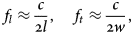
where c is the free-space speed of light. In practice, because of the non-TEM behavior of the electromagnetic field in the gap and the fringing field effects, the actual resonant frequencies may differ from (1). Such equations nevertheless provide a first approximation, which is more accurate the smaller the g/b ratio.
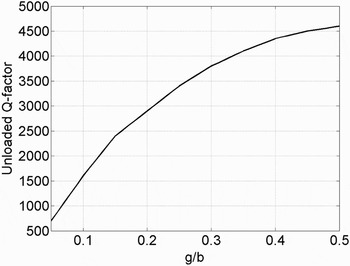
For given resonant frequencies f l, f t, the smaller the gap, the smaller the size of the resonator. At the same time, however, the power handling and the unloaded Q-factor are decreased, as is known for every ridge waveguide structure. By properly sizing the gap, the Q-factor degradation can be maintained as moderate, while the resonator structure is made small enough to fit in a waveguide sized to allow the propagation of the fundamental TE10 mode. Figure 3 shows the unloaded Q-factor computed for square ridge resonators (aluminum surfaces) realized within a WR-90 and resonating at 10 GHz, for different g/b ratios.
Unloaded Q-factor for 10 GHz square ridge resonators realized in WR-90; results computed considering aluminum surfaces (σAl = 38 MS/m).

For symmetry reasons, when the ridge is placed at the center of the waveguide, the incident TE10 mode will excite only the longitudinal mode (Fig. 2(a)), since the transverse mode (Fig. 2(b)) has odd symmetry with respect to the center waveguide axis. The intra-resonator coupling between the two orthogonal modes can easily be realized by a suitable discontinuity, e.g. by chamfering one of the corner edges.
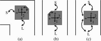
The square ridge resonator can operate in different configurations, depending on the way in which its resonant modes are excited; in Fig. 4 three cases of interest are illustrated.
Square ridge resonators in rectangular waveguide: (a) folded configuration, (b) in-line configuration, and (c) offset configuration.

A) Folded configuration
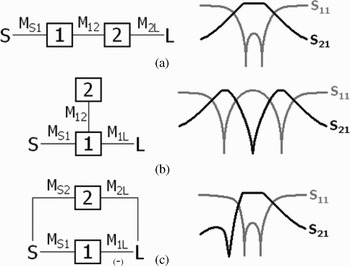
The square ridge is placed at the center of a waveguide rectangular bend (Fig. 4(a)). The two feeding ports are coupled to the two orthogonal modes, independently. One of the ridge corners is chamfered in order to couple the two modes. The coupling and routing scheme along with the corresponding two-pole filtering function is sketched in Fig. 5(a), where the source S and the load L represent the fundamental TE10 mode at the input and output sections, boxes 1 and 2 correspond to the two resonant modes, and the M are coupling coefficients within the filter.
Square coupling and routing schemes with relative synthesizable responses: (a) two-pole filter (folded configuration), (b) dual-band filter with a TZ between two transmission poles (in-line configuration), and (c) two-pole filter with one TZ (offset configuration).

B) In-line configuration
The square ridge is placed at the center of a uniform waveguide (Fig. 4(b)). In this case the feeding ports are coupled to the same resonating mode, i.e. the longitudinal one, the latter being coupled to the other orthogonal mode (transverse) through the chamfered corner. The resulting coupling scheme produces a dual-band behavior, with one transmission zero (TZ) between two transmission poles, as sketched in Fig. 5(b).
C) Offset configuration
The square ridge is offset with respect to the center axis of the waveguide (Fig. 4(c)). In this case the feeding ports are coupled to both resonating modes, and intra-resonator coupling is not present. The resulting coupling scheme is depicted in Fig. 5(c). This kind of filter topology allows for two-pole filtering functions with one TZ whose position (above or below the pass band) depends on the ratio between the resonator frequencies.
III. SINGLE RIDGE FILTERS
In order to implement a large variety of filter functions, a wide range of coupling values has to be provided by the structures. Although intra-coupling (M 12) can easily be modulated by the dimensions of the introduced discontinuity (the extent of chamfering in our case), in order to synthesize the needed input/output coupling (such as M S1 and M 2L) additional elements have to be used in combination with the ridge. Similar to what has been done in [Reference Bastioli, Marcaccioli and Sorrentino8] for rectangular ridge resonators, we verified two approaches to efficiently tune the input/output couplings: irises or posts can be added before the ridge to reduce the coupling strength; ridge taps are used instead to enhance the coupling.
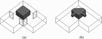
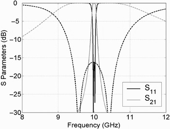
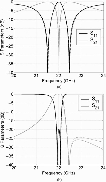
As an example, Fig. 6 shows a square ridge in folded configuration with irises (Fig. 6(a)) and ridge taps (Fig. 6(b)) added at the input/output ports to control the coupling. The corresponding full-wave simulations are shown in Fig. 7, demonstrating the effectiveness of such elements to obtain both narrow-band (solid lines) and wide-band (dashed lines) filtering functions.
Square ridge resonators in folded configuration making use of (a) inductive irises and (b) ridge taps.


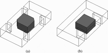
Two single ridge filter structures based on in-line and offset configurations have also been designed: the first is a dual-band filter with pass bands centered at 21.5 and 22.5 GHz, each having 400 MHz bandwidth with 10 dB return loss; the second is a two-pole filter with 22 GHz center frequency, 200 MHz bandwidth, 20 dB return loss, and one TZ above the pass band. The filters have been designed and optimized according to the following normalized 4 × 4 coupling matrices (S, 1, 2, and L are the row and column indexes):
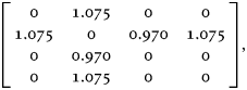
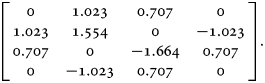
The structures designed are shown in Fig. 8. Both filters are in standard WR-42. Observe that, in the folded and in-line configuration, the taps/irises used for coupling control must be symmetric with respect to the waveguide so as not to vary the coupling scheme of Figs 5(a) and 5(b). Any non-symmetrical element would add in fact a coupling between the feeding ports and the mode resonating perpendicularly to the port axis.
Square ridge resonators: (a) in-line and (b) offset configurations.

A different approach will be used for the offset configuration: in this type of filter the offset of the ridge is directly related to the coupling ratios M S1/M S2 (and M 1L/M 2L). Although additional symmetric coupling-control elements would only alter the absolute values of both couplings yet maintaining their ratio, the use of non-symmetrical elements allows one to modify the ratio so as to have an extended control of all the coupling parameters.
The results of the full-wave simulations by computer simulation technology (CST) Microwave Studio along with the coupling matrix functions are shown in Fig. 9.

IV. MULTIPLE COUPLED RIDGE FILTERS
The single ridge configurations can be used as basic building blocks for the design of higher order filters.
A possible arrangement consists of making the square ridge resonators couple through short waveguide sections, so that no resonances occur within the lengths between adjacent ridges. In this case, it is essential to understand and control the coupling mechanism occurring between the resonant modes of adjacent ridges.
Consider for example Fig. 10, where two square ridges are cascaded within a uniform waveguide. As expected, the longitudinal modes of the ridges are coupled through the fundamental TE10 mode propagating in the section between the ridges (Fig. 10(a)): in this case, as discussed in Section III, inductive irises or ridge taps can be used to vary the coupling. On the other hand, the transverse modes of the ridges are also coupled through higher order modes (Fig. 10(b)). TE20 is mainly responsible for such a coupling. Since the coupling is due to evanescent modes that rapidly decay along the rectangular waveguide section, the distance between the ridges is the main degree of freedom to vary this coupling. These two coupling control mechanisms (ridge taps/irises and distance) are not completely independent; therefore, the desired coupling interaction can only be obtained after some full-wave analysis iterations.
Coupled square ridge resonators: (a) longitudinal mode coupling through fundamental mode and (b) transverse mode coupling through evanescent modes.

In order to show the feasibility of the approach proposed, we have designed two different filters. The specifications of the first one are as follows:
– pass-band: 10–10.2 GHz (f 0 = 10.1 and BW = 0.2 GHz);
– return loss: >18 dB, and
– stop-band attenuation: >25 dB within 9–9.9 GHz and 10.3–11.2 GHz.
A fourth-order filtering function with two symmetrically placed TZs satisfies the requirements: the corresponding normalized 6 × 6 coupling matrix is
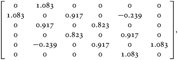
where S, 1, 2, 3, 4, and L are the row and column indexes. The matrix can be synthesized by optimization-based techniques [Reference Amari, Rosenberg and Bornemann9].
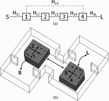
The structure implementing the matrix (4) and its schematic filter topology are shown in Fig. 11. The filter consists of two square ridge resonators realized in folded configuration within a standard WR-90. In the following description, the terms “longitudinal” and “transverse” are used with reference to the propagation direction of the feeding waveguides. In Fig. 11, the longitudinal modes are therefore referred to as 1 and 4 whereas 2 and 3 are indicated as the transverse modes.
Fourth-order pseudo-elliptic filter: (a) coupling and routing scheme and (b) filter structure: resonant modes (solid black arrows with resonator number and E-field maxima signs), sequential coupling (solid gray arrows), and cross-coupling (dotted gray arrow) are indicated.

Inductive irises are placed at the filter input and output to implement the required M S1 and M 4L, whereas intra-couplings M 12 and M 34 are realized by the chamfered corners.
Let us focus on the transverse waveguide branch connecting the two ridges. As discussed above, the transverse resonating modes (2 and 3) are coupled through the TE10 mode propagating within this section (coupling M 23). On the other hand, the longitudinal modes (1 and 4) are mainly coupled through the evanescent modes, this providing the cross-coupling M 14. Moreover, since the two modes resonate in opposition of phase, this being controlled by the relative positions of the chamfered corners, the sign of M 14 is negative as required in the matrix (4). In order to control both values of M 23 and M 14, we used a thick iris whose thickness mainly impacts on the decay of the evanescent modes (related to M 14), whereas the width mostly controls the energy transferred by the TE10 mode (related to M 23).
The structure has been optimized and manufactured to validate the design. The disassembled aluminum prototype is shown in Fig. 12. By neglecting the feeding waveguides, the filter layout is roughly 23 × 48 mm, which is comparable with the size of an ordinary second-order direct-coupled cavity filter. The measurement in Fig. 13 (dashed lines), obtained without any tuning, confirms the full-wave simulations (solid lines). The measured insertion loss at the filter center frequency is 0.3 dB instead of 0.2 dB as simulated: roughness on the inner surfaces can likely be responsible for this minor variation. Concerning the spurious response performance (not shown), the stop-band extends up to 13.7 GHz.
Manufactured filter.

Comparison between simulation (solid lines) and measurement (dashed lines).

The second design is a dual-band filter with the following specifications:
– pass-bands: 9.1–9.5 GHz and 10.5–10.9 GHz
– return loss: >18 dB, and
– stop-band attenuation: >20 dB within 9.7–10.3 GHz.
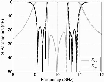
A sixth-order filtering function with three TZs located between two triplets of transmission poles satisfies the requirements. The corresponding normalized 8 × 8 coupling matrix is

where S, 1, 2, 3, 4, 5, 6, and L are the row and column indexes. The structure implementing the matrix (5) and its schematic filter topology are shown in Fig. 14.
Sixth-order dual-band filter: (a) coupling and routing scheme and (b) filter structure: resonant modes, sequential coupling, and cross-coupling are indicated as shown in Fig. 11.

The filter structure consists of three ridges in in-line configuration, realized in a standard WR-90. Ridge taps are used to enhance the coupling between the longitudinal modes of the ridges (M 13 and M 35), whereas the distance between the resonators mainly controls the coupling between the transverse modes (M 24 and M 46). Chamfered corners are used to realize the couplings M 12, M 34, and M 56. Observe that, because of the relative positions of the chamfered corners, the transverse-mode couplings M 24 and M 46 are negative.
The full-wave simulated S parameters are shown in Fig. 15: the simulations performed using both CST and high frequency structural simulator (HFSS) agree quite well, demonstrating the potentialities of this filter.
Full-wave simulation of the dual-band filter of Fig. 14: CST simulation (solid lines) and HFSS simulation (dashed lines).

The structure is about 6 cm long. This result confirms the effectiveness of the in-line configuration to design dual-band filters within a compact uniform rectangular waveguide section.
V. CONCLUSIONS
A new class of dual-mode waveguide filters has been proposed. The structure is based on nearly square ridge resonators realized within short sections of a rectangular waveguide working in the uni-modal region. No enlargements of the waveguide dimensions are necessary to produce mode degeneracy. The nearly square ridge resonator can be used alone to produce filters of second order. Pass-band or dual-band filtering functions are obtained by putting the ridge in a 90° bend (folded configuration) or in a straight waveguide section (in-line configuration), respectively. A pass-band response with one TZ located either in the upper or in the lower stop band is obtained with an offset configuration, i.e. an in-line configuration where the ridge is offset with respect to the waveguide central axis. The use of irises and ridge taps has been proposed as an efficient way of controlling the coupling values and therefore obtaining a wide range of filtering functions. By cascading more ridges and by properly controlling the interaction between them, it is possible to realize filters of arbitrary order and pseudo-elliptic behavior. To demonstrate the feasibility of the approach proposed, two filters have been designed: a fourth-order pseudo-elliptic X-band filter employing two square ridges and a sixth-order dual-band filter employing three ridges. Results show that this approach is highly effective to realize compact filters and sufficiently versatile to produce many different filtering functions.
ACKNOWLEDGEMENTS
Simone Aisa, Damiano Aisa, and Prof. Giovanni Carlotti of the Physics Department of University of Perugia are gratefully acknowledged for accurate manufacturing of the filter.
 Roberto Sorrentino (M'77–SM'84–F'90) received a Doctor degree in electronic engineering from the University of Rome “La Sapienza,” Rome, Italy, in 1971. In 1974, he became an assistant professor of microwaves with the University of Rome “La Sapienza.” From 1977 to 1982, he was an adjunct professor with the University of Catania, the University of Ancona, and the University of Rome “La Sapienza,” where he was then an associate professor from 1982 to 1986. In 1983 and 1986, he was a research fellow with The University of Texas at Austin. From 1986 to 1990, he was a professor with the University of Rome “Tor Vergata.” From November 1990, he has been a professor with the Università Degli Studi di Perugia, Perugia, Italy, where he was the Chairman of the Electronic Department, Director of the Computer Center (1990–1995), and Dean of the Faculty of Engineering (1995–2001). His research activities have been concerned with various technical subjects such as electromagnetic wave propagation in anisotropic media and the interaction of electromagnetic fields with biological tissues, but mainly with numerical methods and computer-aided design (CAD) techniques for passive microwave structures and the analysis and design of microwave and millimeter-wave circuits. He has authored/coauthored over 100 technical papers in international journals and 200 refereed conference papers. He has served the International Union of Radio Science as vice chair (1993–1996) and then chair (1996–1999) of Commission D (Electronics and Photonics). He is the President of the European Microwave Association since its constitution in 1998. He is a member of the High Technical Council, Italian Ministry of Communications. From 1998, he served on the Administrative Committee (AdCom) of the IEEE MTT-S. From January 1995 to April 1998, he was the Editor-in-Chief of the IEEE Microwave and Guided Wave Letters. In 2000, he was one of the recipients of the IEEE Third Millennium Medal. In 2004, he was the recipient of the Distinguished Educator Award presented by the IEEE Microwave Theory and Techniques Society (IEEE MTT-S).
 Luca Marcaccioli was born in Perugia, Italy, on January 8, 1978. He received the Laurea degree (with distinction) in electronic engineering from the University of Perugia, Italy, in 2002. He carried out his thesis research at the Laboratory for High Frequency of the Technical University of Munich (Germany), and then he joined the Department of Electronic and Information Engineering of the University of Perugia (Italy). He has been a visitor student at the Electrical Engineering department of GeorgiaTech (Atlanta, GA, USA), and in January 2006 he received his Ph.D. degree. In September 2007, he was a co-founder of RF-microtech srl, a spin-off company of University of Perugia, and he currently has the role of R&D engineer. He is a member of the European Microwave Association. He was a coauthor of the paper recipient of the Young Engineers Prize at EuMC 2007 held in Munich, Germany. In 2008, he was a coauthor of the paper recipient of the Best Student Paper Award (First Place) at the MTT-S International Microwave Symposium held in Atlanta, USA.
 Simone Bastioli was born in Spoleto, Italy, on June 19, 1981. He received the Laurea degree (with distinction) in electronic engineering from the University of Perugia, Italy, in 2006. In 2005, he carried out his thesis research in Ericsson AB, Mölndal, Sweden, working on the design of waveguide filters and transitions for microwave applications. In 2006, he joined the Department of Electronic and Information Engineering (DIEI) of the University of Perugia, Italy, where he is currently a Ph.D. student. His research activities include the design of microwave filters and diplexers, as well as LTCC and reconfigurable circuits. He is a member of the European Microwave Association. He was the recipient of the 2008 Best Student Paper Award (First Place) presented at the IEEE Microwave Theory and Technique Society (IEEE MTT-S) International Microwave Symposium (IMS), Atlanta, GA, USA, and of the Young Engineers Prize presented at the 2008 European Microwave Conference (EuMC), Amsterdam, The Netherlands.