1. INTRODUCTION
For the past two decades, mobile robot navigation has been of interest to many researchers. Mobile robot navigation is the problem of estimating position, attitude and velocity of a robot with regard to the reference frame (Lü et al., Reference Lü, Xie and Chen2009; Titterton and Weston, Reference Titterton and Weston2004). There are two different navigation approaches: relative and absolute. The most common mobile robot navigation system is odometry, which measures the position of the robot relative to its initial position. In addition, in this way the distance travelled is calculated by counting the robot's wheel encoders. The main drawback of odometry is errors caused by inequality of wheel diameters and wheel slippage. In Borenstein and Feng (Reference Borenstein and Feng.1995), these errors are categorised as systematic, (e.g. different wheel diameters) and non-systematic (e.g. wheel slippage) errors. Different strategies have been proposed to improve the accuracy of navigation systems based on odometry (Schleicher et al., Reference Schleicher, Bergasa, Ocaña, Barea and López2010). In one of these strategies, to correct odometry, a test bench called UMBmark is used (Borenstein and Feng, Reference Borenstein and Feng1996b). In the UMBmark test, the robot was run on a square path several times to calculate the robot's position and attitude errors. Then the odometry errors were corrected using the derived correction factors from the calculated errors and the robot geometrical relationships.
In another method called “Gyrodometry”, a gyro sensor along with odometry is used to determine the position and attitude of the robot (Borenstein and Feng, Reference Borenstein and Feng1996a). In this approach, the main positioning system is odometry and the gyro is a standby positioning system. When the robot traverses over a bump, the odometry fails to provide accurate position and orientation. Therefore, the robot's position and orientation is calculated utilising the gyro. After traversing the bump, the odometry is reset by the positioning system based on the gyro. From this point, the odometry will be utilised again as the main positioning system. Then, the gyro data is corrected for drift error utilising the approach proposed in Barshan and Durrant-Whyte (Reference Barshan and Durrant-Whyte1995).
In another approach, an information fusion algorithm based on different versions of Kalman Filter (KF) for integrating multi-sensor information was introduced to estimate the robot position (Sadeghzadeh-Nokhodberiz et al., Reference Sadeghzadeh-Nokhodberiz, Poshtan, Wagner, Nordheimer and Badreddin2014a; Reference Sadeghzadeh-Nokhodberiz, Poshtan, Wagner, Nordheimer and Badreddin2014b). In Barshan and Durrant-Whyte (Reference Barshan and Durrant-Whyte1995) and Hanlin Sheng and Zhang (Reference Hanlin and Zhang2015), an inertial navigation system was employed to calculate the robot position and attitude using a tri-axial gyroscope, a tri-axial accelerometer, and two electro-level tilt sensors. Moreover, in these references an Extended Kalman Filter (EKF) was proposed to solve nonlinearity problems in the estimation of the position and attitude of the mobile robot by an inertial system. The results presented in these works show that the EKF reduces the estimation error of position and attitude.
However, the precision of the EKF is limited because of the linearization of the system model (Arasaratnam and Haykin, Reference Arasaratnam and Haykin2009; Gundimada and Asari, Reference Gundimada and Asari2009; Hu and Huang, Reference Hu and Huang2010; Xue et al., Reference Xue, Jiang, Chang, Yang, Qin and Yuan2012; Teslić et al., Reference Teslić, Škrjanc and Klančar2010) and assumption of Gaussian measurement noise, which is not always established (Hu and Huang, Reference Hu and Huang2010). Therefore, nonlinear filters, which can estimate nonlinear functions without linearization, are introduced to estimate the nonlinear nature of the odometry errors. To this end, an integrated navigation algorithm based on an Unscented Kalman Filter (UKF), which estimates mean and covariance without linearization of the nonlinear function, is proposed in Houshangi and Azizi (Reference Houshangi and Azizi2005), where the UKF was used to determine the mobile robot position and orientation by integrating information from odometry and a fibre optic gyroscope. The estimation results of a mobile robot's position and orientation compared to the EKF algorithm was improved.
The UKF is more accurate than the EKF when applied to nonlinear systems (Canelon et al., Reference Canelon, Provence, Shieh and Liu2007; Grewal and Andrews, Reference Grewal and Andrews2011; Houshangi and Azizi, Reference Houshangi and Azizi2005), however, in systems with high dimensions, due to the increase of the computation complexity, the filter convergence would be extremely slow. Moreover, to achieve a proper estimation, the tuning parameters of the UKF should be accurately adjusted. Sigma points in a particle filter are chosen randomly based on the system Probability Density Function (PDF). Nevertheless, in the Cubature Kalman Filter (CKF), they are chosen based on a mathematical equation (cubature law). Therefore, the number of sigma points in the particle approach is much greater than in a CKF. Consequently, the calculation cost in a particle filter is higher and its speed is less.
Thus, more accurate nonlinear filtering for estimating states of high dimensional systems based on cubic radial spherical rules (CKF) was proposed. In this approach, linearization of the nonlinear model is tackled using cubature point sets to approximate the mean and variance (Arasaratnam and Haykin, Reference Arasaratnam and Haykin2009). The third-order accuracy of the system can be achieved with this method. Because of its high accuracy and low computational burden (Gadsden et al., Reference Gadsden, Al-Shabi, Arasaratnam and Habibi2014; Ge et al., Reference Ge, Xu and Wen2014; Jia et al., Reference Jia, Xin and Cheng2013), the CKF can be widely used in attitude estimation and navigation. Hence, as one of the most promising research directions, employing the CKF algorithm for cooperative location with high precision and relatively low computation load is an emerging research topic in multiple mobile robot systems (Sun et al., Reference Sun, Diao, Zhang and Li2017; Xu et al., Reference Xu, Gao, Liu and Liu2014).
Motivated by these considerations, in this work, a novel algorithm for integrating the information of the robot's position and orientation based on an inertial sensor and odometry using the CKF is proposed. In addition, a new nonlinear system and measurement models are established for the measurements from an Inertial Navigation System (INS) and odometry. The proposed approach is not only simple to implement, but also can reduce the computational complexity and improve the accuracy of the localisation. Comparing the obtained results from applying the CKF algorithm instead of the EKF algorithm manifests its better applicability and reliability.
The remainder of this paper is organised as follows: in Section 2, mobile robot position and orientation determination based on odometry is presented. Section 3 includes some explanations of equations of the inertial navigation systems. The algorithm of CKF is briefly introduced in Section 4. Section 5 encompasses the compounding of information. Simulation results are presented in Section 6, which is then followed by comparing the proposed algorithm and the EKF algorithm. Finally, conclusions and suggestions for future work are presented.
2. POSITION DETERMINATION BASED ON ODOMETRY
To calculate more accurate position and orientation, two positioning systems are utilised. The first and most basic positioning system is odometry and the second positioning system uses information from an Inertial Measurement Unit (IMU).
The robot's position is defined by
 $\underline{P}\lpar kT_{s}\rpar = \lsqb \underline{p}\lpar kT_{s}\rpar \comma \; \psi\lpar kT_{s}\rpar \rsqb ^{T}$
at time step kT
s
; where k is a positive integer and T
s
is the sampling period. For simplicity T
s
is dropped from the notation after this point and the mobile robot is assumed to be traveling on a flat surface. The vector
 $\underline{p}\lpar k\rpar = \lsqb p_{x}\lpar k\rpar \comma \; p_{y}\lpar k\rpar \rsqb ^{T}$
specifies the robot's Cartesian position, and ψ(k) defines the robot orientation. The kinematic model of the mobile robot is given by:
 $$\left\{ {\matrix{ {p_x(k + 1) = p_x(k) + {\rm }\left( {\displaystyle{{v_r(k) + v_l(k)} \over 2}} \right)T_s\cos \left( {\psi (k)} \right)} \hfill \cr {p_y(k + 1) = p_y(k) + {\rm }\left( {\displaystyle{{v_r(k) + v_l(k)} \over 2}} \right)T_s\sin \left( {\psi (k)} \right)} \hfill \cr {\psi (k + 1) = \psi (k) + {\rm }\left( {\displaystyle{{v_r(k) - v_l(k)} \over b}} \right)T_s} \hfill \cr } } \right.$$
where v r and v l are the robot right and left wheel velocities, respectively. ψ(k) is the angle between the robot direction and the X-axis, and b is the distance between the two wheels.
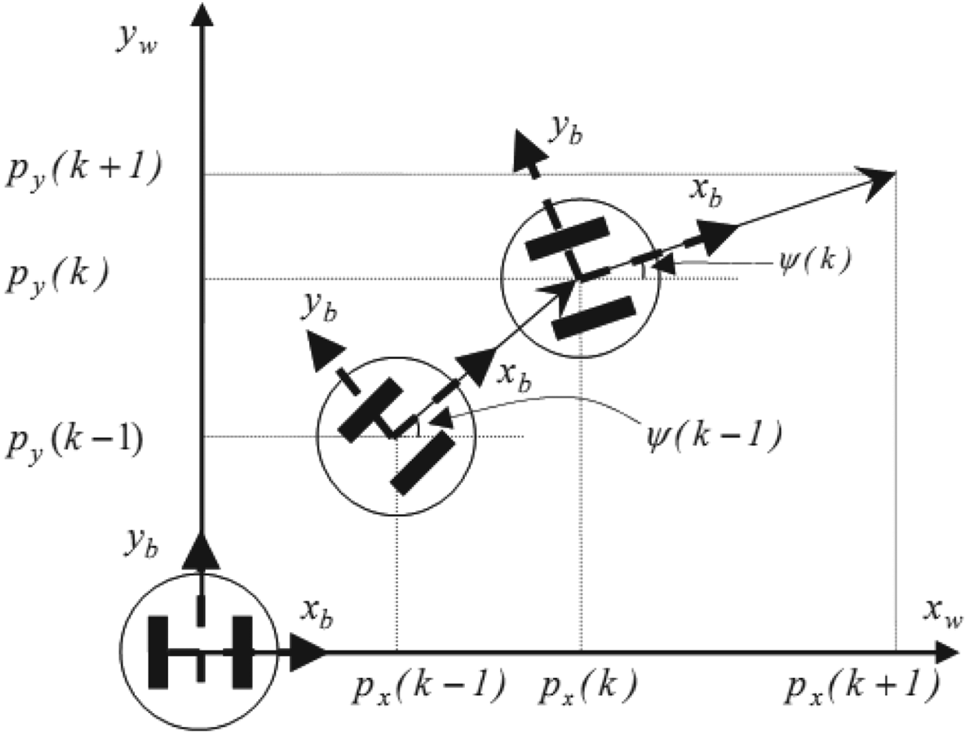
To characterise the mobile robot's motion, two coordinate frames are defined. The body coordinate frame (x
b
, y
b
), as shown in Figure 1, is selected so that x is forward and y is lateral with the origin located at the robot's kinematics centre. The world coordinate frame (x
w
, y
w
), is stationary and attached to the initial position of the robot. Initially, the body coordinate frame coincides with the world coordinate frame. As shown in Figure 1, the position vector
 $\underline{P}\lpar k\rpar $
is updated during the mobile robot motion with respect to the world coordinate frame.
Mobile Robot position with respect to the World Coordinate Frame.

The robot position vector based on odometry is estimated incrementally by:
 $$\eqalign{& ^o \underline{p} (k + 1) = ^o\underline{p} (k) + R_{\psi _o}(k){\underline{v} }^b(k) \cr & \psi _o(k + 1){\rm } = \psi _o(k) + {\dot \psi }_o(k)T_s} $$
where
 $v^{b}\lpar k\rpar = \lsqb v^{b}_{x} \lpar k\rpar \comma \; v^{b}_{y} \lpar k\rpar \rsqb ^{T}$
, is the robot velocity in the body coordinate frame,
 $R_{\psi_{o}}\lpar k\rpar $
denotes the rotational transformation matrix from the body coordinate frame to the world coordinate frame and ψ
o
(k) and
 $\dot{\psi}_{o}\lpar k\rpar $
, are the robot orientation and its angular velocity.
 $R_{\psi_{o}}\lpar k\rpar $
is specified by:
 $$R_{\psi _o}(k) = \left[ {\matrix{ {\cos \psi _o(k)} & { - \sin \psi _o(k)} \cr {\sin \psi _o(k)} & {\cos \psi _o(k)} \cr } } \right]$$
The velocity component
 $v^{b}_{y}\lpar k\rpar $
is assumed to be zero because of the robot's forward motion.
 $v^{b}_{x}\lpar k\rpar $
and
 ${\psi_{\circ}}\lpar k\rpar $
are calculated by:
 $$\eqalign{& {v_x^b} (k) = \displaystyle{1 \over 2}(v_{er}(k) + v_{el}(k)) \cr & {{\dot \psi }_{^\circ}} (k) = \displaystyle{{v_{er}(k) - v_{el}(k)} \over b}} $$
where v er (k) and v el (k) are the robot's right and left wheels' translational velocities, respectively. v er (k) and v el (k) are known from reading the encoder values and b is the robot wheelbase.
3. EQUATIONS OF THE INERTIAL NAVIGATION SYSTEM
In any INS, inertial sensors (accelerometers and gyroscopes) have been used to measure accelerations and angular velocity of a vehicle in relation to the inertial space. An Inertial Measurement Unit (IMU) is used to measure all accelerometers and gyroscopes of a system. The output information of the IMU enters the inertial processing unit in which inertial calculations of position, attitude and velocity of the system are performed at each moment in relation to the reference system, which is the Earth's coordinates, in the current work. In the coordinates of the Earth, the navigation operation is conducted as follows:
-
I. Position in a navigation system is calculated as:
(5) $$\left\{ {\matrix{ {\dot L = \displaystyle{{v_N} \over {R_0 + h}}} \hfill \cr {\dot l = \displaystyle{{v_E} \over {{\rm (}R_0 + h{\rm )}\cos L}}} \hfill \cr {\dot h = - v_D} \hfill \cr } } \right.$$

where L, l and h are coordinates of a vehicle, and stand for Earth coordinates latitude, longitude and altitude of the vehicle, respectively. Moreover,
 $v_N,\;v_E\;and\;v_D$
indicate the velocity of the vehicle in the North, East and Down directions toward the centre of the Earth. R
0 is the radius of the Earth, assumed as 6,378,140 metres.
-
II. To determine the attitude of the vehicle, the following equation is used.
(6)
$$\dot{C}^e_b = {C}^e_b \lpar \Omega^b_{ib} - {C}^e_b\Omega^e_{ie}\rpar $$

In the above equation,
 $\Omega^{b}_{ib}$
and
 $\Omega^{e}_{ie}$
are the anti-symmetric output vector of the gyroscope with the angular velocity of the Earth, and
 $C^{e}_{b}$
is the Direction Cosine Matrix (DCM) that converts the vector from coordinates of the navigation system into Earth coordinates. The anti-asymmetric matrix is also defined as follows:
 $$x = \left[ {\matrix{ {x_1} & {x_2} & {x_3} \cr } } \right]^T \Rightarrow X = \left[ {\matrix{ 0 & { - x_3} & {x_2} \cr {x_3} & 0 & { - x_1} \cr { - x_2} & {x_1} & 0 \cr } } \right]$$
-
III. The velocity of the vehicle is determined using the following equations:
(8)
$$\matrix{ {{\rm }\left\{ {\matrix{ {{\dot v}_N = f_N - v_E(2\Omega + \dot l)\sin L + v_D\dot L + \xi g} \hfill \cr {\quad {\mkern 1mu} \; = f_N - 2\Omega v_E\sin L + \displaystyle{{v_Dv_N - v_E^2 \tan L} \over {R_0 + h}} + \xi g} \hfill \cr {{\dot v}_E = f_E - v_N(2\Omega + \dot l)\sin L + \mathop {v_D}\limits^. (2\Omega + \dot l)\cos L - \eta g} \hfill \cr {\quad {\mkern 1mu} \; = f_E + 2\Omega (v_N\sin L + v_D\cos L) + \displaystyle{{v_E} \over {R_0 + h}}(v_D + v_N\tan L) - \eta g} \hfill \cr {{\dot v}_D = f_D - v_E(2\Omega + \dot l)\cos L - v_N\dot L + g} \hfill \cr {\quad {\mkern 1mu} \; = f_D - 2\Omega v_E\cos L - \displaystyle{{v_E^2 + v_N^2 } \over {R_0 + h}} + g} \hfill \cr } } \right.} \hfill \cr } $$

where
 $f_{N}\comma \; f_{E}\;{and}\ f_{D}$
are the acceleration of the vehicle in the North, East, and Down directions within the navigation system, respectively. They can be calculated from the following equation:
 $$\matrix{ {f^n} \hfill & { = C_b^n f^{b}} \hfill \cr {f^n} \hfill & { = [f_N\quad f_E\quad f_D]} \hfill \cr } $$
where f
b
is the calculated vector of the output of the accelerometers and
 $C^{n}_{b}$
is the DCM that is used for carrying the calculated quantities of accelerometers used in the body navigation system into the reference navigation system. In Equation (8), g
l
is the local gravity vector of the Earth that can be estimated as follows if the elliptical effect of the Earth is neglected:
 $$g_l = \left[ {\matrix{ {\xi g} & {\eta g} & g \cr } } \right]^T = \left[ {\matrix{ 0 & 0 & {9\cdot 791719} \cr } } \right]^T$$
4. CUBATURE KALMAN FILTER ALGORITHM
All known filters suffer from problems such as divergence and the “curse of dimensionality”. The result of the “curse of dimensionality” is widely seen in state-space models with more than 20 states in the state vector. In other words, as the dimension increases the sample size must increase exponentially to keep a predefined level of accuracy for a given estimator. Here, divergence is due to different reasons such as:
-
• The incorrectness or the deficiency of the available physical model of the system.
-
• The inaccuracy or the unreliability of the information in measuring the function of density distribution.
-
• The high dimension of nonlinear equations that simulate the state-space.
-
• The computational and quantitative errors.
The CKF has been recently introduced to solve the problems of high dimensions and divergence that exist in previous version of KFs. This filter is a nonlinear filter that is established to estimate high dimension states based on spherical-radial rules. The cubic rules have no need to be differentiated; therefore, this algorithm can be used for those functions that are inherently difficult to be differentiated or their Hessian and Jacobian matrices cannot be computed.
The algorithm of the Cubature Kalman Filter includes the following steps:
-
1) Suppose the primary density of the k − 1 moment has been calculated by the obtained data until the (k − 1)th moment. This density can be analysed as follows:
(11)where
$$P_{k-1 \vert k-1} = S_{k-1 \vert k-1}S^{T}{_{k-1 \vert k-1}}$$
$S=\sqrt{P}$
and
$\lpar \sqrt{P}\rpar _{i}$
denotes the ith row or column of the square root matrix P. If P = S
T
S, then i is the row number of S, and if P = SS
T
, then i is the column number of S. Furthermore, to find
$\lpar \sqrt{P}\rpar _{i}$
, one can use the Cholesky factorisation method. However, the Singular Value Decomposition (SVD) method, which is simpler and more precise, is suggested.
-
2) The cubic points are calculated as follows:
(12)where m = 2n, n is the number of the states, and ξ i denotes the i-th member of the below set, called the set of cubature points (Zarei and Shokri, Reference Zarei and Shokri2015):
$$\chi_{i,k-1 \vert k-1} = S_{k-1 \vert k-1}\xi_{i} + \hat{x}_{k-1 \vert k-1}\quad i=1,2, \ldots ,m$$
$$\sqrt {\displaystyle{m \over 2}} \left\{ {\left( {\matrix{ 1 \cr 0 \cr \cdot \cr \cdot \cr \cdot \cr 0 \cr } } \right),\left( {\matrix{ 0 \cr 1 \cr \cdot \cr \cdot \cr \cdot \cr 0 \cr } } \right),\left( {\matrix{ 0 \cr \cdot \cr \cdot \cr \cdot \cr \cdot \cr 1 \cr } } \right), \ldots ,\left( {\matrix{ { - 1} \cr 0 \cr \cdot \cr \cdot \cr \cdot \cr 0 \cr } } \right),\left( {\matrix{ 0 \cr { - 1} \cr \cdot \cr \cdot \cr \cdot \cr 0 \cr } } \right), \ldots ,\left( {\matrix{ 0 \cr 0 \cr \cdot \cr \cdot \cr \cdot \cr { - 1} \cr } } \right)} \right\}$$
-
3) In this step, the cubic points are passed through the process equation, which represents the system dynamic:
(13)
$$\chi^{\ast}_{i,k \vert k-1}= F(\chi_{i-k-1 \vert k-1, u_{k-1}})$$
-
4) By using the calculated points and by applying weights of the cubic points, the primary estimation is calculated as follows in the time update stage:
(14)
$$\hat x_{k \vert k - 1} = \displaystyle{1 \over m}\sum\limits_{i = 1}^m {\chi _{i,k \vert k - 1}^ * } $$
-
5) The covariance matrix is calculated as follows in the time update stage:
(15)
$$P_{k \vert k - 1} = \displaystyle{1 \over m}\sum\limits_{i = 1}^m {\chi _{i,k \vert k - 1}^* } \chi _{i,k \vert k - 1}^{*T} - \hat x_{k \vert k - 1}\hat x_{k \vert k - 1}^T + Q_{k - 1}$$
-
6) In this step, the computed matrix in step (5) is re-analysed as follows to compute new cubic points:
(16)
$$\eqalign{& P_{k \vert k - 1} = S_{k \vert k - 1}S^T_{k \vert k - 1} \cr & \chi _{i,k \vert k - 1} = S_{k \vert k - 1}\xi _i + {\hat x}_{k \vert k - 1}} $$
-
7) In this step, the computed points must be passed through the measuring model:
(17)
$$\eqalign{ Y_{i,k \vert k-1}= H(\chi_{i,k \vert k-1}, u_{k})}$$
-
8) By considering the calculated points and by applying the weights of the cubic points, the output of the system is estimated as follows:
(18)
$$\matrix{ {{\hat y}_{k \vert k - 1} = \displaystyle{1 \over m}\sum\limits_{i = 1}^m {y_{i,k \vert k - 1}} } \hfill \cr } $$
-
9) In this step, the covariance matrices associated with the output and intersecting with the input-output of the system are computed to calculate the gain of the KF.
(19)
$$\matrix{ {P_{yy,k \vert k - 1} = \displaystyle{1 \over m}\sum\limits_{i = 1}^m {Y_{i,k \vert k - 1}} - {\hat y}_{k \vert k - 1}\hat y_{k \vert k - 1}^T + R_k} \hfill \cr {P_{xy,k \vert k - 1} = \displaystyle{1 \over m}\sum\limits_{i = 1}^m {X_{i,k \vert k - 1}} - {\hat x}_{k \vert k - 1}\hat y_{k \vert k - 1}^T } \hfill \cr } $$
-
10) Compute the gain of the KF as follows:
(20)
$$\matrix{ {W_k = P_{xy,k \vert k - 1}P_{yy,k - 1}^{ - 1} } \hfill \cr } $$
-
11) In the measurement update stage, the new estimation is computed by utilising a new measurement as follows:
(21)
$$\matrix{ {{\hat x}_{k \vert k} = {\hat x}_{k \vert k - 1} + W_k(y_k - {\hat y}_{k \vert k - 1})} \hfill \cr } $$
-
12) Updating the covariance matrix:
(22)
$$\matrix{ {P_{K \vert K} = P_{k \vert k - 1} - W_kP_{yy,k \vert k - 1}W_k^T } \hfill \cr } $$
-
13) To compute the next updated estimated state, steps 1 to 12 should be repeated.


5. INTEGRATING THE INERTIAL NAVIGATION SYSTEM WITH THE ODOMETRY
In the previous research, the EKF is used to determine the robot's position and orientation by integrating information from multiple sensors (Borenstein and Feng, Reference Borenstein and Feng.1995; Reference Borenstein and Feng1996a; Reference Borenstein and Feng1996b). The EKF was developed to extend the application of the Kalman filter to nonlinearity issues. The CKF achieves better performance than the EKF in dealing with nonlinear problems (Jwo et al., Reference Jwo, Hu and Tseng2013; Wendel et al., Reference Wendel, Meister, Schlaile and Trommer2006; Zhao and Slotine, Reference Zhao and Slotine2005). This paper demonstrates the applicability of using the CKF for a more accurate mobile robot position determination.
5.1. Data fusion by using the extended Kalman filter
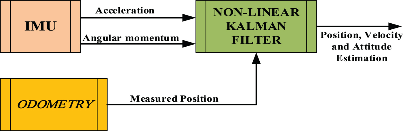
Figure 2 shows the block diagram of data fusion by using extended Kalman filters. As shown in this figure, the difference between the estimated position from INS and the measured position from the odometry are considered as the computed input of the EKF.
 $$\matrix{ {y = \left[ {\matrix{ {\delta P_{INS,X} - \delta P_{odometry,X}} \cr {\delta P_{INS,Y} - \delta P_{odometry,Y}} \cr } } \right]} \hfill \cr } $$
The Algorithm of Integrating INS/ODOMETRY by EKF.

The process equation is considered as:
 $$ \eqalign{{\delta x_k} \hfill & = {F(\delta x_{k - 1},u_{k - 1})} \hfill \cr {\delta x} \hfill & = {{\left[ {\matrix{ {\delta L} & {\delta l} & {\delta V_n} & {\delta V_E} & {\phi _N} & {\phi _E} \cr } } \right]}^T} \cr {\bf u} \hfill & = {{\left[ {\matrix{ {\delta {\bf f}^B} & {\delta {\bf \omega }_{IB}^B } \cr } } \right]}^T}} $$
where δ x includes the vector of attitude error, the vector of velocity error and the vector of rotating attitude error. The input u includes the main sources of errors that are known as errors of accelerometers and gyroscopes.
Now, the EKF is exploited to estimate INS errors. By applying these errors, INS parameters will be updated to rectify errors and prevent instability of the system. It should be mentioned that these errors are calculated after data sampling.
5.2. Data fusion by using nonlinear Kalman filters
In Figure 3, the general structure of fusion algorithm for the navigation system using nonlinear Kalman filters is shown. It is clear from this figure that this structure consists of an auxiliary navigation system (i.e. odometry) and an estimation algorithm such as an unscented or cubature Kalman filter, which estimate the navigation states.
The algorithm of integrating INS/ODOMETRY using a CKF.

In this structure, linear and angular acceleration and position of the body are measured at each step by using IMU and auxiliary navigation systems, respectively. Then, the state estimator (unscented or cubature Kalman filter) estimates the navigation system states (position, velocity and the situation of moving the body) without any error. The process state equation is expressed as follows:
 $$ \eqalign{ {x_k} \hfill & = {F(x_{k - 1},u_{k - 1})} \hfill \cr x \hfill & = {{\left[ {\matrix{ L & l & {V_n} & {V_E} & {\phi _N} & {\phi _E} \cr } } \right]}^T} \hfill \cr {\bf u} \hfill & = {{\left[ {\matrix{ {{\bf f}^B} & {{\bf \omega }_{IB}^B } \cr } } \right]}^T}} $$
where x denotes the position, velocity and rotational position vector. Input u includes the linear and angular velocities measured by the IMU. Also, the measurement equation for fusion by using nonlinear filters is expressed in Equation (26):
 $$y = \left[ {\matrix{ {P_{odometry,X}} \cr {P_{odometry,Y}} \cr } } \right]$$
The proposed data fusion approach in this section is not only simple to implement, but can also reduce the computational complexity and improve the accuracy of the localisation. Moreover, the main advantage of using this method is that correction can be completed using at least one available measurement signal (y) or IMU. The more measurement signals become available, the more accurate the estimation will be.
6. SIMULATION RESULTS
In this section, the suggested algorithm has been analysed based on a set of simulated data that was obtained from a robot movement over 600 seconds. The goal in this simulation is to examine the applicability of the proposed approach for short and long runs.
The gyroscopes and accelerometers' scaling factor error and biases are considered as follows:
 $$\eqalign{S_g &= diag\left[ {\matrix{ {{10}^{ - 2}} & {{10}^{ - 2}} & {{10}^{ - 2}} \cr } } \right]\quad ({\rm deg}/h) \cr S_a &= diag\left[ {\matrix{ {{10}^{ - 2}} & {{10}^{ - 2}} & {{10}^{ - 2}} \cr } } \right]\quad \,(m/s^2) \cr \varepsilon _{const}^B &= \left[ {\matrix{ {0\cdot 2} & {0\cdot 2} & {0\cdot 2} \cr } } \right]\quad \,\,\,\,\,\,\,\,\,\,\,\,\,\,\,\,\,\,({\rm deg}/h) \cr \eta _{const}^B &= \left[ {\matrix{ {{10}^{ - 4}g_0} & {{10}^{ - 4}g_0} & {{10}^{ - 4}g_0} \cr } } \right] \;(m/s^2)} $$
where S
g
and S
a
are 3 × 3 diagonal matrices whose principal diagonal elements are valued considering the gyroscopes and accelerometers' scaling factor error. Furthermore,
 $\varepsilon^{B}$
and η
B
are the gyroscopes and accelerometers' biases.
In addition, numerical values of measurement noise covariance R, process noise covariance Q, initial estimation of the states
 $\hat x_0$
and initial error of the covariance P
0 for the nonlinear Kalman filters are considered as follows:
 $$\matrix{ R \hfill & { = [{10}^{ - 12}\quad {10}^{ - 12}]} \hfill \cr Q \hfill & { = diag[{10}^{ - 4}\quad {10}^{ - 4}\quad {10}^{ - 4}\quad {10}^{ - 4}\quad {10}^{ - 4}]} \hfill \cr {\hat x} \hfill & { = {[53\quad - 1\cdot 7\quad 0\quad 1\cdot 41\quad 0]}^T} \hfill \cr {P_0} \hfill & { = diag[{10}^{ - 3}\quad {10}^{ - 3}\quad {10}^{ - 2}\quad {10}^{ - 2}\quad {10}^{ - 1}]} \hfill \cr } $$
It is worth mentioning that roll and pitch angles are equal to zero due to the robot movement on the ground. Moreover, the downward acceleration in the vertical direction (centre of the Earth) will not be considered. Therefore, in this study, only the heading and angular velocity along the East and North directions are estimated.
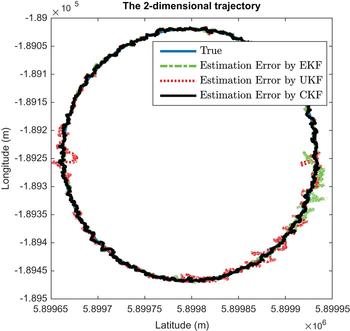
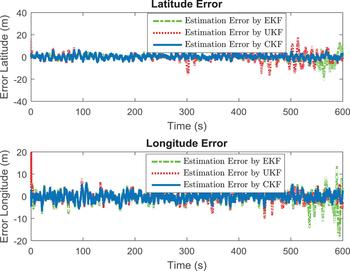
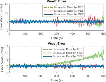
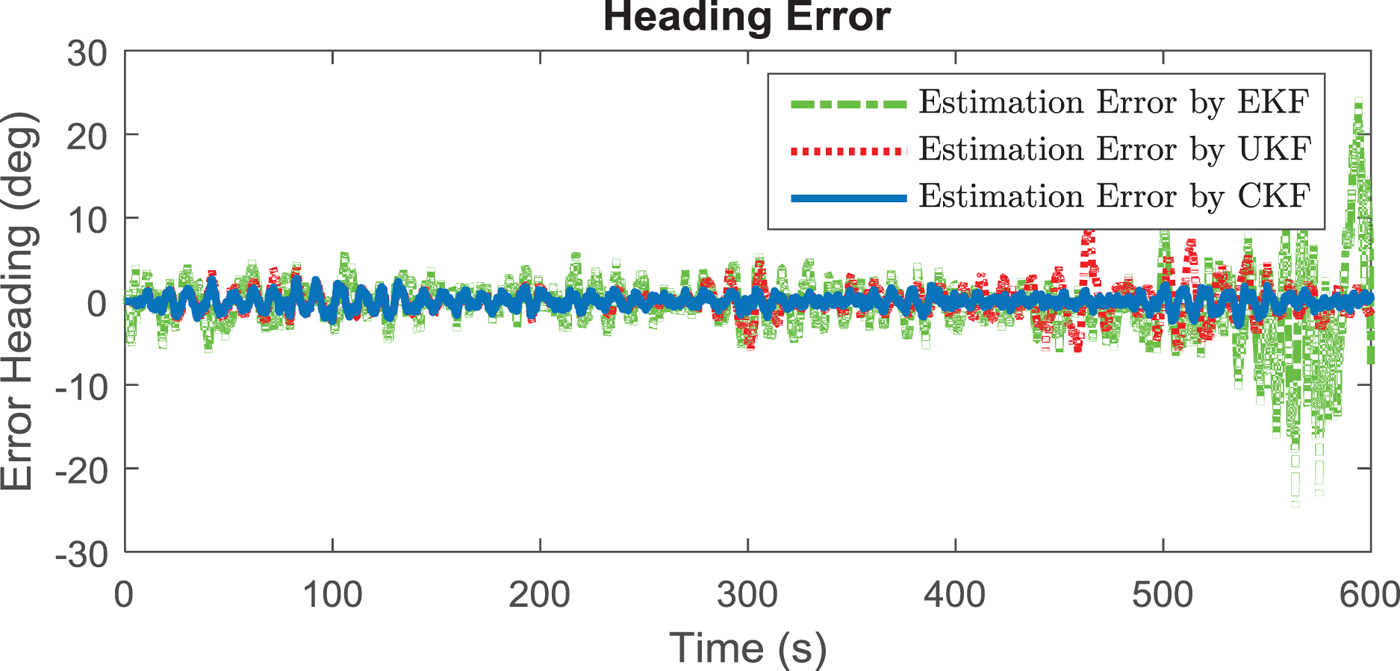
The robot's final position and orientation are recorded and the estimates of the robot's position along the North and East and the orientation based on the EKF, UKF, and CKF, using information from the INS, and odometry are compared with the actual trajectory. Width, length, and the velocity in North and East directions are calculated by the EKF, UKF and CKF algorithms and are compared with the real quantity of these parameters. The obtained results are shown in Figures 4 to 7.
Two-dimensional trajectory of the robot.

Latitude estimation error (above), longitude estimation error (below).

Vnorth estimation error (above), Veast estimation error (below).

Heading estimation error.

To analyse the reliability of the approach the experiment was repeated twenty times. The averages of final position and orientation errors for twenty runs are listed in Table 1. Based on the obtained results, it can be argued that the CKF provides position and orientation that are more precise than other positioning systems such as odometry, IMU and those corrected by the EKF.
RMSE of Position and Orientation Errors for Twenty Runs.

7. CONCLUSION
In this paper, a new method that exploits the cubature Kalman filter is proposed to increase the accuracy and authenticity of the estimation of a mobile robot position and orientation. The obtained results derived from simulation tests show that using the CKF algorithm, compared to the EKF, and UKF can noticeably increase the precision of the position and velocity of the vehicle since this algorithm is inherently nonlinear. In future works, this algorithm can be used to decrease errors of the system and integrate measured data from other aided navigation systems such as magnetic systems, terrain navigation systems and others.