Introduction
Multiple-input-multiple-output (MIMO) technology exploits the spatial and polarization diversity through different channel communication [Reference Paulraj, Gore, Nabar and Bolcskei1]. Dual-polarized antennas (DPAs) are investigated with different structures over the past decade. Most of the designs are implemented with crossed dipole and patch antennas [Reference Cheng, Li and Lu2–Reference Yang, Zeng, Wen, Zou and Pan5]. In [Reference Fusco and Rao6] four circularly polarized antennas are utilized to provide dual slant 45° polarization. Wide bandwidth antennas with polarization diversity increase the high channel capacity. In recent years, many efforts have been made to develop antennas that possess low-profile, wideband, and dual polarization characteristics [Reference Zhou, Wong and Yeung7–Reference Wu, Geng, Wang, Zhou, Zhao, He, Liang, Zhu and Jin10]. When the distance between dipole antenna and perfect electric ground plane approaches zero, the total radiating electric field diminishes in all directions [Reference Huang, De, Zhang, Sarkar and Carlo11]. To avoid the degradation of antenna performance, several approaches have been implemented using artificial surfaces such as electromagnetic bandgaps (EBGs) and artificial magnetic conductors (AMCs).
AMCs exhibit unique property that is in-phase reflection coefficient at a certain frequency which makes them similar to magnetic conductors. A wideband bow-tie dipole antenna with an AMC reflector reported in [Reference Zhu, Li, Liao and Xue12] achieved 7 dBi gain, 31% bandwidth, with a height of 0.19λ0. A wideband omnidirectional antenna was proposed in [Reference Wu, Yang, Chen, Qu and Nie13], where the antenna backed with an AMC reflector achieved 45% impedance bandwidth at a height of 0.25λ0. By using a wideband AMC reflector with 54.8% reflection phase bandwidth for a dual-polarized dipole antenna in [Reference Li, Li, Wang, Zhou and Cheung14] an isolation of more than 25 dB is achieved. Nonuniform metasurface is utilized for a low-profile DPA in [Reference Zhu, Qiu and Wei15] for reducing overall height by 0.1λ0. A low-profile printed dipole is proposed in [Reference Zhai, Xi, Zang and Li16] to achieve a bandwidth of 22% and a height of 0.07λ0. A dual band AMC reflector is designed to achieve a low profile for a dual polarized antenna in [Reference Liu, Liu, He and He17] at a height of 0.013λ0 with port to port isolation of 20 dB.
Mitigation of mutual coupling with sensible isolation is extremely tight in closely spaced MIMO antennas. Some of the proposed techniques to reduce the mutual coupling are by using decoupling networks, complementary split ring resonators (SRRs), and defected ground structures as reported in [Reference Nadeem and Choi18]. For dual-band DPAs a frequency selective surface (FSS) is developed for coupling reduction of −20 dB [Reference Zhu, Chen and Yang19]. A metasurface wall is constructed between two MIMO antennas for minimizing the mutual coupling more than 38 dB [Reference Yin, Feng and Gu20]. A decoupling method by using a periodic array of SRRs loaded with transmission line between two MIMO antennas for LTE band 40 antennas is proposed in [Reference Bellary, Kandasamy and Rao21]. Recently, EBG structure with defected ground is utilized as decoupling technique to obtain 10–40 dB isolation between slotted patch antennas [Reference Sokunbi and Attia22].
In this paper, a low profile, wideband dual-polarized MIMO antenna with FSS decoupling technique is presented. The novelty of the proposed antenna configuration is by introducing rectangular slots on the bow-tie antenna placed on either side of the FR4 substrate and a square ring surrounding it for obtaining a wide bandwidth. Compactness of the bow-tie antenna is obtained by miniaturizing the radiator to 0.4λ0. The proposed chessboard-based AMC surface is loaded with a dual-polarized MIMO antenna by maintaining the profile height of 0.125λ0. For 1 × 2 MIMO, an FSS wall is constructed with wide bandstop characteristics from 2.85 to 4.75 GHz to mitigate the near-field coupling between the DPA elements. From simulated and measured results mutual coupling reduction of 27 dB over the existing coupling and bandwidth of 57.14% (2.95–4.95 GHz) for VSWR<2 with port isolation of more than 25 dB are achieved.
Antenna design
Dual-polarized bow-tie antenna on chessboard AMC reflector
The geometry of the proposed DPA on a chessboard AMC reflector is shown in Fig. 1(a). The dual-polarized MIMO antenna consists of radiator, feed lines, and chessboard AMC surface. The dual polarization is achieved by two crossed bow-tie antennas represented as bow-tie antenna 1 and 2 and chessboard-based AMC reflector is constructed with two different AMC unit cells. The main radiator of the proposed antenna is made up of two planar-printed bow-tie elements in the orthogonal orientation placed on either side of the FR4 substrate with a relative dielectric constant of 4.4. The rectangular slots on each arm of the radiator are provided to improve isolation between the antenna elements. The chamfering on edges of each arm enhances the port to port isolation and also suppresses the cross polarization levels. The two 50 Ω coaxial cables are utilized to feed the two independent bow-tie antenna elements as shown in Fig. 1(b). In addition, a square ring is designed around the radiator for proper impedance matching and for improving the bandwidth. The compactness of the radiator is achieved by miniaturizing the radiating structure to 0.4λ0. The top patches on the substrate acts as radiator and the corresponding two patches at bottom side of substrate refers to ground for both the bow-tie antenna elements. The AMC reflector is fabricated on an FR4 substrate with a relative dielectric constant of 4.4. AMC surface consists of a periodic structure with 5 × 5 unit cells, which consists of a square patch having a side length of 0.21λ0. Optimizations are carried out using FEM-based 3D electromagnetic (EM) simulation software Ansoft HFSS 19.0. The optimized dimensions for the proposed DPA are tabulated in Table 1.
(a) Geometry of the proposed low-profile DPA configuration. (b) Side view of low-profile DPA.

Optimized dimensions of the proposed 1 × 2 MIMO antenna

Measured and simulated S-parameters for the DPA element are shown in Fig. 2(a). From measured results it is observed that with a VSWR of <2 and an isolation of more than 25 dB is reported for the entire band of interest. The measured gains for both the antenna elements are shown in Fig. 2(b). An average gain of 8 dB is observed for both polarized antenna elements.
(a) Simulated and measured S-parameters of DPA. (b) Measured gain plot of DPA.

AMC reflector design and analysis
The geometry of the AMC unit cell at 3.5 GHz is designed with a square patch consisting of four rectangular slots and a crossed slot at center of the square as shown in Fig. 3(a). Similarly, the geometry of the dual-band AMC unit cell at 3.1 and 4.5 GHz includes a square patch, metallic ground placed on either side of the dielectric FR4 substrate with thickness of 1.6 mm and relative permittivity of 4.4 as shown in Fig. 3(b). The individual unit cells of the proposed chessboard AMC surface, as shown in Fig. 1(a), has a size of 0.21λ0. From the in-phase property of the AMC surface the phase of the reflected wave varies from −90 to +90°. The performance evaluation of an infinite repetition of the unit cells is simulated by using EM simulation software Ansoft HFSS 19.0. Since, in the design the bow-tie antenna elements are oriented with slant 45° angles a linearly polarized EM wave with 45° incident angle is applied to both the AMC surface unit cell via port 1. Due to the symmetry of AMC cells about the x-axis it exhibits same properties for ϕ = 45° incident angle. Figures 4(a) and 4(b) show the reflection phase with various incident angles θ increasing from 0 to 60° for AMC cells 1 and 2 respectively. The optimized dimensions of the designed AMC unit cells are tabulated in Table 1.
(a) Geometry of the proposed AMC unit cell at 3.5 GHz. (b) Geometry of the proposed dual-band AMC unit cell at 3.1 and 4.5 GHz.

Simulated reflection phase diagram of plane wave with polarization angle ϕ = 45° for different incident angles θ: (a) AMC cell 1 and (b) AMC cell 2.

1 × 2 MIMO antenna design and analysis
Wide bandstop FSS unit cell
The proposed FSS unit cell is based on fractal structures with two square metal rings, printed on either side of the FR4 substrate with a dielectric constant of 4.4 and a thickness of 1 mm. The structure of FSS unit cell element is shown in Fig. 5(a). The frequency response of the proposed FSS unit cell is simulated by EM simulation software Ansoft HFSS 19.0. Figure 5(b) shows the simulated result with scattering parameters of the proposed FSS unit cell. It was found that, when the outer square ring is absent, the FSS structure yields a narrow bandstop of 1.3 GHz. With the ring printed on the substrate, the FSS yields a wide bandstop from 2.85 to 4.75 GHz. A wide bandstop of 1.9 GHz in the range of 2.85–4.75 GHz was achieved at −10 dB. The optimized dimensions of the designed wide bandstop FSS unit cell are tabulated in Table 1.
(a) Geometry of the proposed wide bandstop FSS unit cell. (b) Simulated S-parameters of wide bandstop FSS unit cell.

1 × 2 MIMO antenna with decoupling structure design
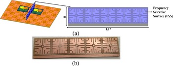
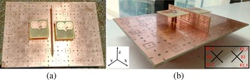
The 1 × 2 MIMO antenna configuration with dual-polarized bow-tie antennas is shown in Fig. 6(a). The edge to edge spacing between the elements is considered as 0.18λ0. To analyze the effect of mutual coupling between the each polarized antenna element specific nomenclature is given for the 1 × 2 MIMO configuration as shown in Fig. 7(b). By introducing the FSS wall, the effect of mutual coupling is analyzed between two MIMO antennas. The schematic and fabricated prototype of the FSS wall is shown in Fig. 6(b). By inserting FSS wall between the two adjacent antenna elements it reduces the mutual coupling by attenuating the entire operating band of the bow-tie antenna elements. The additional horizontal strip at the bottom of FSS wall is utilized for mounting the FR4 vertical strips in between the MIMO antenna elements which also provides the return path to the ground plane by isolating the each MIMO antenna element. By optimizing the dimensions and position of the array of FSS it is observed that there is significant reduction of mutual coupling between MIMO antenna elements. The fabricated prototype of the complete 1 × 2 MIMO antenna configuration is shown in Fig. 7.
(a) Low-profile 1 × 2 MIMO antenna configuration with FSS wall. (b) Fabricated prototype of FSS wall.

(a) Top view and (b) isometric view of the fabricated low-profile 1 × 2 MIMO antenna with FSS wall.

Decoupling mechanism of FSS wall
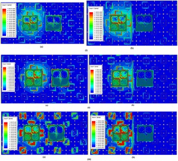
The surface current has great impact on port to port isolation and mutual coupling in MIMO antennas. The designed 1 × 2 MIMO antenna and its surface current distributions with/without FSS wall when port E1-1 is activated are analyzed in Fig. 8. It is observed that the surface current concentrates at bow-tie antenna elements and at the feed position where two coaxial feed structures are inserted. Hence the field lines mainly occur around the square ring and bow-tie antenna elements in both cases. To understand the effect of FSS wall over the band of interest the current distributions are observed at various frequencies. Figures 8(i), 8(ii), and 8(iii) depict the surface current plots at 3.1, 3.5, and 4.5 GHz, respectively.
Surface current distribution of the 1 × 2 MIMO antenna when port E1-1 is activated at (i) 3.1 GHz, (ii) 3.5 GHz, and (iii) 4.5 GHz for (a) without FSS wall and (b) with FSS wall.

In the case without the FSS wall (Fig. 8(a)), a significant amount of current mutually induces on the other antenna element. In the case with the FSS wall (Fig. 8(b)), less current induces on the other antenna elements due to the presence of vertical FSS wall inserted in between two antenna elements. Since the array of FSS couples the majority of mutual field it enables to minimize the surface currents generated between the adjacent antenna elements. The height of the FR4 vertical substrate is also optimized for effective mitigation of mutual coupling among the MIMO antenna elements. The port to port isolation between the antenna ports with and without FSS wall is shown in Fig. 9(a). Without FSS wall low isolation is reported (<22 dB) is observed between ports E1-1, E1-2 and ports E2-1, E2-2. However, noticeably there is improved isolation (<25 dB) between the ports E1-1, E1-2 and ports E2-1, E2-2 for entire band of interest. Effects of mutual coupling between each polarized antenna element in both the scenarios that is with and without FSS wall are shown in Fig. 9(b). In the absence of FSS wall between the antenna elements coupling is around 20–22 dB between ports E1-1, E2-1 and ports E1-2, E2-2. By introducing wide bandstop FSS wall the coupling reduction of 27 dB is achieved between ports E1-1, E2-1 and ports E1-2, E2-2 in band of interest.
Measured (a) port to port isolation and (b) mutual coupling reduction with and without FSS wall in 1 × 2 MIMO antenna.

Results and discussion
Measured results of 1 × 2 MIMO antenna
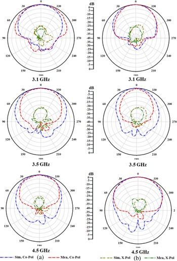
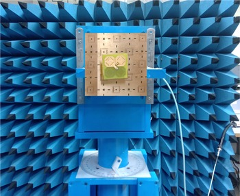
Figure 10(a) depicts the simulated and measured S-parameters plot for both the antenna elements. It is observed that the antenna operates for wideband from 2.95 to 4.95 GHz with VSWR of <2. From the measured results antenna provides a good isolation of 25–30 dB as shown in Fig. 10(b). The simulated and measured radiation patterns at various frequencies of 3.1, 3.5, and 4.5 GHz for dual-polarized MIMO antenna element in both E and H planes when port E1-1 is excited are shown in Figs 11(a), 11(b), and 11(c), respectively. The measured cross polarization levels are less than −25 dB in both E- and H-planes with a high front-to-back ratio of 28 dB. The difference in simulated and measured results may be attributed to the measurement and manufacturing errors. The measurement setup for the proposed MIMO antenna element is shown in Fig. 12. The performance comparison of the proposed MIMO antenna with and without chessboard AMC surface is given in Table 2. The purpose of loading the dual-polarized bow-tie antenna with chessboard AMC surface is to obtain low profile and enhance the gain over complete band of interest. To understand the necessity of the low-profile, wideband DPAs, the proposed antenna is compared with already existing antennas and results are tabulated in Table 3.
Measured and simulated results: (a) reflection coefficient and (b) port to port isolation in 1 × 2 MIMO antenna.

Simulated and measured normalized radiation patterns when port E1-1 is excited for MIMO antenna element: (a) E-plane and (b) H-plane.

Measurement setup of MIMO antenna element.

Performance of proposed MIMO antenna element with and without chessboard AMC surface

Performance comparison of the proposed MIMO antenna element with previous antenna designs

MIMO performance analysis
To evaluate the performance of MIMO antenna system, the basic important parameters envelope correlation coefficient (ECC), diversity gain (DG) and total active reflection coefficient (TARC) are considered. Due to complex tedious far-field measurement in this paper, ECC and DG are calculated using measured S-parameters and supported by simulated far-field radiation patterns. ECC by using S-parameters is computed by using the following formula [Reference Sharawi23]:

where (i, j) ∈ (i, j) |1 ≤ i < j ≤ 4, i, j ∈ N|.
ECC by using far-field pattern of the antennas with both phase and polarization information is given by following formula [Reference Sharawi23]:

where F i (θ,ϕ) is the radiated field of the “i” antenna.
For far-field measurement the simple equivalence principle infinitesimal dipole models technique along with Ansys HFSS field calculator are utilized. With source current distributions J m(r) = J mx($\hat {x}$ ) + J my($\hat {y}$
 ) + J mz($\hat {z}$
 ) and m = 1 to n; here n = 4, ECC for MIMO antennas is computed by using the formula in [Reference Sarkar and Srivastava24]. By considering the functions are Gaussian in elevation and uniform in azimuth the angular density functions $P_\theta$
 = $P_\theta$
 (θ,ϕ) and $P_\phi$
 = $P_\phi$
 (θ,ϕ) are calculated by using formulas given in [Reference Sarkar and Srivastava24].
Under far-field conditions, generally two different scenarios are considered. For first case, isotropic power distribution having cross polarization power ratio that is XPR = 0 dB is assumed and the diversity performance is calculated as an ideal case. For understanding the realistic behavior under outdoor scenario, Gaussian power distribution for both horizontal and vertical components having m v = m h = 80°, σv = σh = 15° with XPR = 1 dB is assumed for the second case. Similarly the other parameter DG related to ECC is calculated by using the following formula [Reference Sharawi25]:

The evaluated data for ECC and DG are given in Table 4. Measured ECC using S-parameters for the 1 × 2 MIMO antenna with and without the proposed FSS is shown in Fig. 13(a). It is observed that the ECC of the MIMO antenna with FSS is less than 0.05 in operating band. TARC is defined as the ratio of the square root of the total reflected power divided by the square root of the total incident power in a multi-port antenna system [Reference Sharawi25]. It can be computed by using S-parameters of MIMO antenna system. For two port antenna system TARC is given as,

where θ is the input feeding phase. Measured TARC using S-parameters for 1 × 2 MIMO antenna is shown in Fig. 13(b). From the obtained results it indicates that the proposed decoupling structure when integrated with MIMO antenna have better diversity performance. The performance comparison of the proposed the 1 × 2 MIMO antenna with other referenced antennas are reported in Table 5.
Measured (a) ECC and (b) TARC of the proposed 1 × 2 MIMO antenna with and without FSS.

Simulated ECC and DG using far-field patterns

Performance comparison of the 1 × 2 MIMO antenna with referenced antennas

Note: E-E refers to edge to edge spacing between MIMO antenna elements.
Conclusion
A low-profile, wideband dual-polarized 1 × 2 MIMO antenna with FSS decoupling technique is presented. Low profile is realized by chessboard-based AMC surface designed with two different AMC cells operating at 3.5, 3.1, and 4.5 GHz. The compactness of the antenna is achieved by miniaturizing the antenna to 0.4λ0. A wide bandstop FSS wall from 2.85 to 4.75 GHz is designed to suppress near-field coupling between the MIMO antenna elements. Measured results show by inserting FSS wall vertically, coupling reduction of 27 dB is achieved. The low-profile antenna with bandwidth of 57.14% (2.95–4.95 GHz) for a VSWR of <2 with port isolation of more than 25 dB are obtained for entire band of operation.
 Anudeep Bellary received his B.Tech. degree in Electronics and Communication Engineering from JNTUA, Andhra Pradesh, India in 2013 and M.Tech. degree in Communication Engineering from VIT University, Tamil Nadu, India in 2015. He is the student member of IEEE. He worked as research scientist for more than 1 year at SAMEER-Center for Electromagnetics, Chennai, India. He is presently a Ph.D. research scholar at the Department of Electronics and Communication Engineering, National Institute of Technology Karnataka, Mangalore, India. His field of research includes antennas, multi-in multi-out (MIMO) antennas, mutual coupling, and metamaterials.
 Krishnamoorthy Kandasamy received the B.E. degree in electronics and communication engineering from Bharathiar University, Coimbatore, India, in 2003, his M.E. degree in communication systems from the College of Engineering, Guindy, Anna University, Chennai, India, in 2007, and his Ph.D. degree in electrical engineering from IIT Bombay, Mumbai, India, in 2016. He is currently an Assistant Professor with the Department of Electronics and Communication Engineering, National Institute of Technology, Surathkal, India. His current research interests include metamaterials, antenna engineering, microwave integrated circuits (MICs), and monolithic MICs.
 Patnam Hanumantha Rao received his B.Tech. degree from Sri Venkateswara University, Tirupati, India, his M.S. degree from the Birla Institute of Technology and Science, Pilani, India, and his Ph.D. degree from the Queen's University of Belfast, Belfast, U.K. He was with the Space Applications Center, Indian Space Research Organization, Ahmedabad, India, for 2 years. After that, he joined the SAMEER-Center for Electromagnetics, Chennai, India. He has more than 30 years of research experience in antennas and electromagnetics. In 2010, he steered a computational electromagnetic cell, a joint collaborative project by IISc–SAMEER to analyze complex electromagnetic problems such as antennas on ship, satellite, and aircraft. He has authored over 100 papers in journals and conferences and presented papers in various national and international conferences. His current research interests include antenna designs for multi-in multi-out (MIMO), massive MIMO, and switched beam antenna arrays for 5G communications applications.