Introduction
In recent decades, after Sinclair has introduced the concept of the scatter matrix [Reference Sinclair1, Reference Sinclair2] and Huynen did essential research in this field [Reference Huynen3, Reference Huynen4], the benefit of polarimetric sensor systems has been discussed intensively and the number of approaches getting the desired information is vast. According to the field of application, proposed systems vary in the selection of the frequency band, as well as the types of polarizations, used. Especially in automotive applications, the usage of linearly polarized electromagnetic waves measuring a full polarimetric scatter matrix is very common [Reference Visentin, Hasch and Zwick5]. These systems deliver complete polarimetric information and several theories for decomposition have been introduced [Reference Cloude and Pottier6]. The same result can be achieved using the four possible combinations of circularly polarized radar waves. Both sets are equivalent in their content of information and can be mathematically transformed from one into each other. Calibration of both systems is necessary, which can be accomplished using particular in-scene reflectors [Reference Wiesbeck and Riegger7, Reference Visentin, Hasch and Zwick8].
At the turn of the millennium, the idea of compact polarimetric modes was developed for SAR systems. In these approaches, the completeness of the scatter matrix is not necessary and lower effort for calibration accrues [Reference Raney9]. The decreasing number of required antennas and the amount of data storage space, energy budget and system requirements for data evaluation form benefits while comparable performances can be achieved. The usage of compact polarimetric modes has been proven and compared in SAR-satellite systems for decades [Reference Nord, Nord, Ainsworth, Lee and Stacy10] or are even well known as they have been used to detect the presence of ice in our planetary system since the 1990s [Reference Slade, Butler and Muhleman11]. However, even though they are not popular in automotive applications, they could increase the measurement repetition rate and downsize the architecture of radar systems. Furthermore, reducing the amount of transmitting devices to one, leads to a decrease of observation periods which simplifies and improves the data evaluation of strongly time depended automotive scenarios [Reference Schmid, Feger, Pfeffer and Stelzer12, Reference Niemeijer13].
There are different compact polarimetric modes, which can be distinguished into three different types regarding polarization. The  $\pi /4$-mode is the most famous one using just linearly polarized waves [Reference Souyris, Imbo, Fjortoft, Mingot and Lee14]. The transmitting antenna, which is rotated by
 $45^\circ $ with respect to the two orthogonally oriented linear receiving antenna, led to this denotation. The dual-circular polarimetric mode (DCP) deals with circularly polarized waves only and transmits one sense of rotation while receiving both [Reference Stacy and Preiss15]. Because types of the last category use linearly as well as circularly polarized waves, they have been named systems with hybrid polarization architecture [Reference Raney9]. Accordingly, circular-transmit-linear-receive (CTLR) systems transmit circularly polarized waves and receive coherent dual linear polarization.
There will be a mass of different issues in the near future by developing driving assistance systems or cars with autonomous driving implementation. Each of the before mentioned modes may be appropriate for one or more of these particular missions. In order to compare which approach fits best, a sensor system, which is able to measure a variety of compact polarimetric modes and full polarimetric, too, has been designed and put into operation. The system's center frequency is set to 77 GHz. Continuous or frequency modulated waves (CW or FMCW ) within 1 GHz bandwidth can be transceived. The architecture of the sensor system is kept modular to adjust the amplifying or beam-forming component to specific assignments and modulation schemes.
After some theoretical basics concerning compact polarimetric approaches, the following section deals with the characterization of the sensor system. Afterward a closer look will be taken on the radiation patterns of the microstrip antennas and a planoconvex dielectric lens which is used to form the beam in subsequent measurement set-ups. These set-ups are arranged to check the functionality of the sensor systems and to reproduce an automotive scenario, the double bounce recognition. The usability of DCP and CTLR will be analyzed and compared with full polarimetric results.
Scattering vectors
In comparison with full polarimetric mode, the number of values which have to be measured can be reduced, leading to the name compact polarimetry. The scattering vector of full polarimetric systems can be written as
 $$ {\vec {k}}_L = [S_{HH};S_{HV};S_{VH};S_{VV}], $$
where  $S_{ab}$ represent the complex backscattering terms. These can be transformed into a circular basis using
 $$\left[ {\matrix{ {S_{LL}} & {S_{LR}} \cr {S_{RL}} & {S_{RR}} \cr } } \right] = 0.5\left( {\left[ {\matrix{ 1 & {-i} \cr 1 & i \cr } } \right]\left[ {\matrix{ {S_{HH}} & {S_{HV}} \cr {S_{VH}} & {S_{VV}} \cr } } \right]\left[ {1\,\quad 1-i\,\quad i} \right]} \right),$$
according to [Reference Knott, Tuley and Shaeffer16], while the indices H, V and L, R represent linear horizontal or vertical and circular left- or right-handed polarizations.
The scattering vector of DCP is reduced to just two values. If a right-handed circularly polarized antenna is used to transmit, the target vector will contain the values
 $$ {\vec {k}}_{DCP} = [S_{RR};S_{RL}]. $$
If a left-handed corresponding antenna transmits, all subscripts have to be inverted. The target vector of the hybrid mode CTLR, which will be used in this contribution, can be declared as
 $$ {\vec {k}}_{CTLR} = [S_{RH};S_{RV}], $$
if a right-handed circularly polarized antenna is used. For left-handed transmission, the subscript R has to be replaced by L.
Sensor system
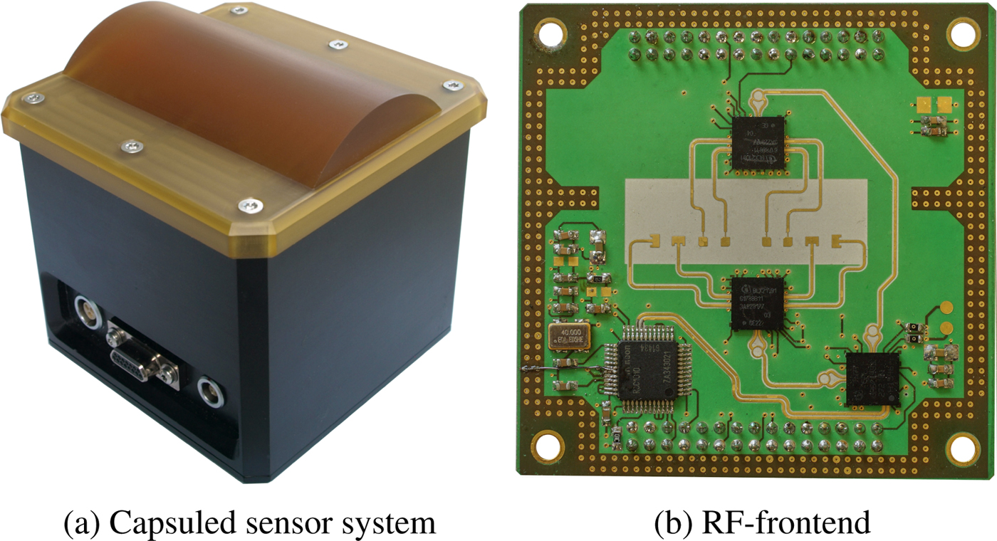
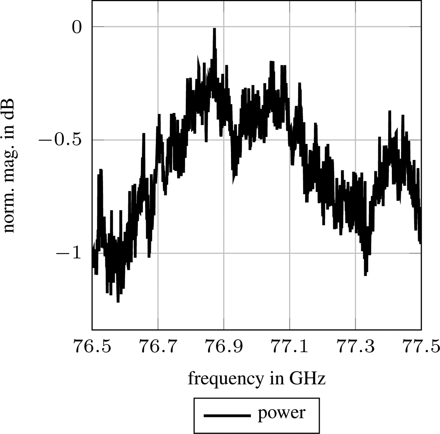
The presented sensor system, which can be seen assembled in Fig. 1(a), has been designed to compare many different possibilities of several classification issues in automotive applications especially for solutions concerning compact polarimetry. Detailed information about the basic set-up and the circuit of the RF-fronted ofFig. 1(b) can be found in a previous contribution [Reference Erhart, Lutz, Walter, Mantz, Hügler and Weigel17]. The generated waveform can be programmed to CW or FMCW. Measurements in the following sections are conducted using frequency ramps of 1 GHz bandwidth and 1 ms duration. The transmitted power deviation over frequency can be seen plotted in (Fig. 2).
Presented sensor system. (a) Capsuled sensor system (b) RF-frontend.

Deviation of transmitted power during frequency chirp.

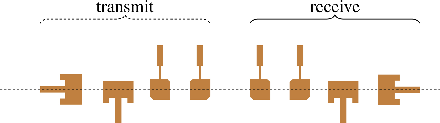
The two types of antennas will be explained in the subsequent subsection. Both have been rotated or mirrored to achieve linear and circular polarizations in both alignments or directions of rotation respectively. Each antenna is placed twice on the RF-PCB so that all combinations can be measured in bi-static mode and direct comparisons are possible. This array can be seen in the middle of Fig. 1(b) and sketched and magnified in Fig. 3. The amplification, as well as the control of the system via SPI, is done on separate PCBs. The A/D conversion is done externally, thus compact geometrical dimensions and a modular setup are guaranteed. During operation, the power amplifiers of the TRX modules can be controlled using a USB connection.
Patch array of the microstrip antennas with different polarizations.

Microstrip patches
Linearly polarized patch
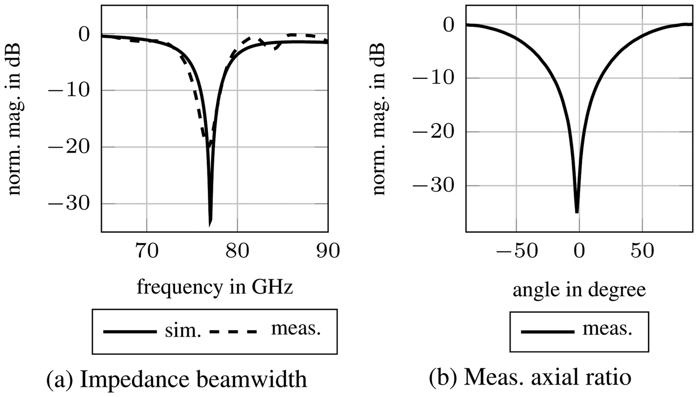
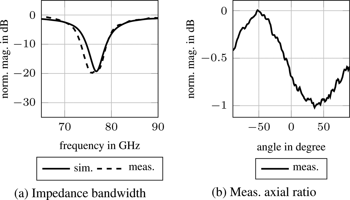
The linearly polarized microstrip antenna, which is represented in Fig. 4, excited in  ${\rm TM}_{10}$ mode exclusively, radiates a wave that is polarized linearly and parallel to the direction of the feed. Its impedance matching is adjusted to a frequency bandwidth from about 76–78 GHz. The quality of this matching is shown in Fig. 5(a). To measure the polarization which is transmitted by the microstrip patch, a pyramidal horn was used as a receiving component placed in and turned around boresight direction of the microstrip antenna which is transmitting a constant frequency of 77 GHz [Reference Golio18, p. 6–127]. The axial ratio, which is defined as the ratio between the minor and major axis of the polarization ellipse, can be gathered from the diagram in Fig. 5(b) by dividing greatest by smallest value. While ideal linearly polarized antennas would exhibit infinite axial ratio values, the measured value of about 35 dB is sufficient for the kind of technical usage in this contribution.
Sketch of a linearly polarized microstrip antenna.

Impedance bandwidth and axial ratio measurement results of a linearly polarized microstrip antenna. (a) Impedance beamwidth (b) Meas. axial ratio.

Circularly Polarized Patch
In general, there are two different ways to radiate circular polarization using microstrip antennas [Reference Richards, Lo and Harrison19]. Firstly, there are dual-feed antennas which rely on feeding networks that accomplish equal amplitudes and a  $90^\circ $ phase difference between two orthogonal excitation points. Secondly, there are antennas with just one feed which are dependent on the existence of two modes orthogonal to each other. In comparison, the dual-feed antennas offer a higher impedance and axial ratio bandwidth but a lower 3 dB axial ratio beamwidth and they are in need of more space due to the feeding network [Reference Lo and Lee20, p. 10–57]. Because the two latter mentioned properties are important criteria for a good performance of our sensor system, microstrip antennas with one feed have been chosen.
Many different shapes of radiating devices with a single feed have been investigated, yet[Reference Gao, Luo and Zhu21, p. 1–9]. The presented sensor system is equipped with truncated corner square microstrip patches, which are designed to obtain a resonance frequency of 77 GHz in both diagonal directions. The truncation of two corners, which is shown in Fig. 6, leads to the presence of a higher mode with a phase difference of  $90^\circ $. These two radiating electric fields are not parallel to the linearly polarized microstrip patches resulting in low crosstalk. By truncation of the other two remaining corners, the sense of direction can be reversed. The impedance bandwidth is shown in Fig. 7(a). The axial ratio measurements have been performed using a pyramidal horn antenna as the receiving component and turning around boresight direction in the same way as before. The two extremes can be found at the expected angles around
 $\pm 45^\circ $ and lead to an axial ratio value of about 1 dB.
Sketch of a truncated corner square microstrip antenna transceiving right-handed circular polarization.

Impedance matching and axial ratio measurement results of a circularly polarized truncated corner square microstrip antenna. (a) Impedance bandwidth (b) Meas. axial ratio.

Dielectric Lens
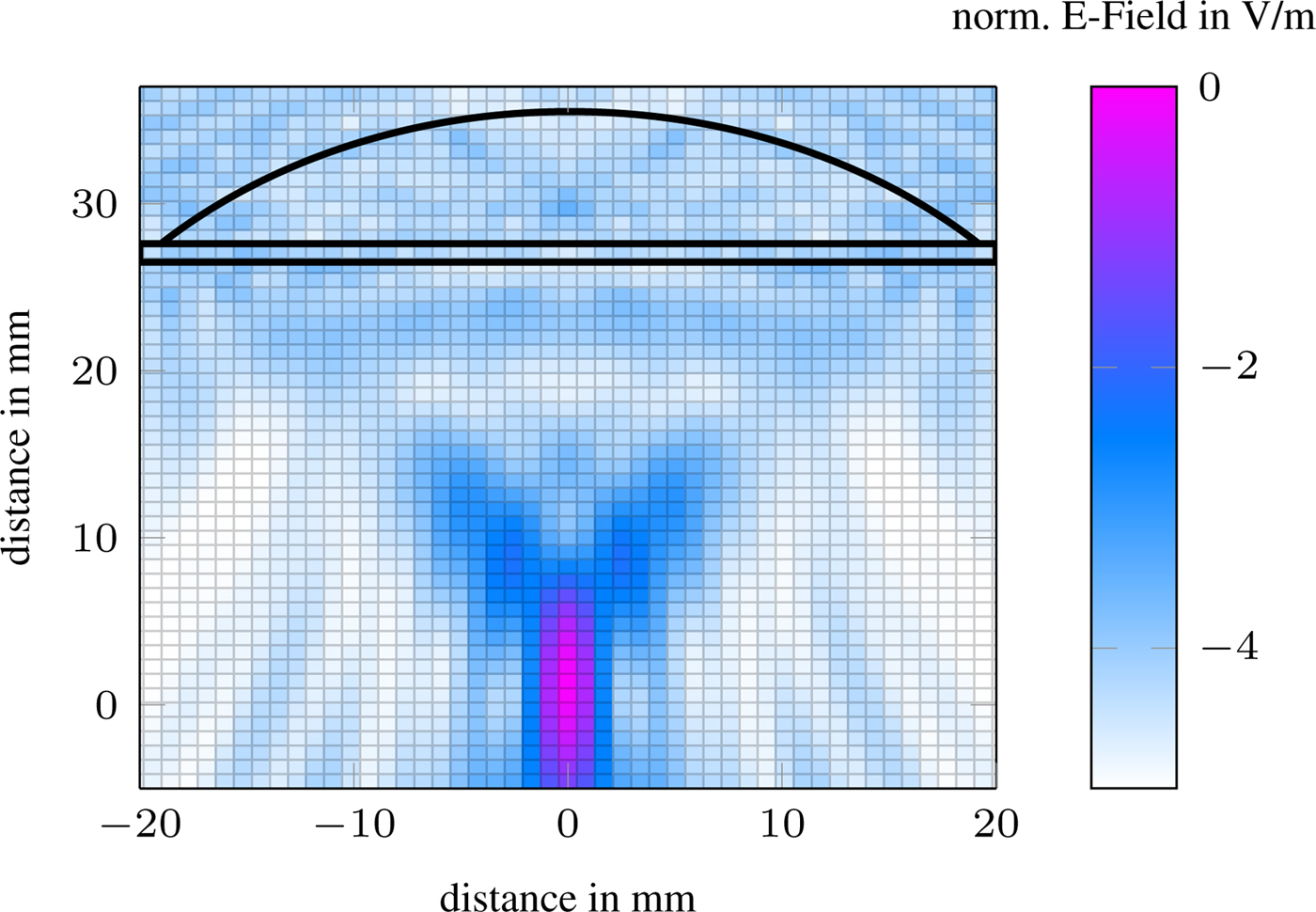
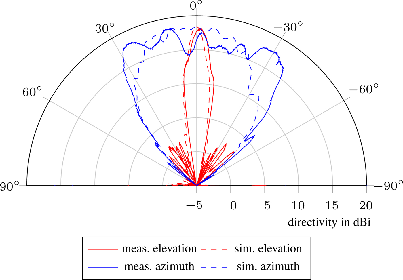
The shape of the dielectric lens, as shown in Fig. 1(a), is used to focus the linearly and circularly polarized waves. Because of the recognition of double bounces and the characterization of surface textures are of primary interest, focusing is requested in elevation direction only. Hence, a planoconvex cylindrical lens, which is made of polyetherimide, has been chosen as the beam-forming component. By optimizing this lens two aims have to be achieved. Firstly, the focal plane has to be adapted to the distance between the lens and the before mentioned mircrostrip antennas. The simulated results regarding the distribution of the electric field are represented in the contour plot in Fig. 8. The microstrip antennas are placed at the origin of this Cartesian coordinate system. Secondly, the geometry of the lens has to be adjusted until the desired emission attunes. As described before, a narrow focusing in the direction of elevation is required while the electromagnetic waves should spread widely orthogonal thereto. A one-way antenna diagram of the dielectric lens fed by one of the circular microstrip antennas is plotted in Fig. 9. Dashed lines represent results from simulations, solid ones are based on measurements.
Simulated distribution of the E-Field effected by a plane wave approaching from top.

One-way antenna diagram of the dielectric lens fed by a microstrip antenna.

Evaluation measurements
A perfect object to check or calibrate a polarimetric radar system is a square angled dihedral. The polarimetric backscattering depends on the angle between the orientation of the polarization plane of the antenna and the axis of the dihedral. The scattering matrix can be evaluated by
 $$\left[ {\matrix{ {S_{HH}} & {S_{HV}} \cr {S_{VH}} & {S_{VV}} \cr } } \right] = \left[ {\matrix{ {\cos (2\psi )} & {\sin (2\psi )} \cr {\sin (2\psi )} & {-\cos (2\psi )} \cr } } \right],$$
in which ψ represents the rotation angle of the dihedral in boresight direction [Reference Huynen4]. The results from several measurements conducted with linearly polarized antennas and varying angle ψ can be depicted descriptively using the Pauli decomposition [Reference Jong-Sen Lee22, p. 214f]. Here the scatter matrix is divided into the Pauli basis and the corresponding coefficients α, β, and γ.
 $$\left[ {\matrix{ {S_{HH}} & {S_{HV}} \cr {S_{VH}} & {S_{VV}} \cr } } \right]{\rm } = \displaystyle{1 \over {\sqrt 2 }}\left( {\alpha \left[ {\matrix{ 1 & 0 \cr 0 & 1 \cr } } \right] + \beta \left[ {\matrix{ 1 & 0 \cr 0 & {-1} \cr } } \right] + \gamma \left[ {\matrix{ 0 & 1 \cr 1 & 0 \cr } } \right]} \right).$$
Furthermore, to check the circularly polarized results, they can be transformed into a linear basis using
 $$\left[ {\matrix{ {S_{HH}} & {S_{HV}} \cr {S_{VH}} & {S_{VV}} \cr } } \right] = 2\left( {\left[ {\matrix{ 1 & 1 \cr i & {-i} \cr } } \right]\left[ {\matrix{ {S_{LL}} & {S_{LR}} \cr {S_{RL}} & {S_{RR}} \cr } } \right]\left[ {\matrix{ 1 & i \cr 1 & {-i} \cr } } \right]} \right),$$
before the Pauli decomposition can be applied [Reference Knott, Tuley and Shaeffer16, p. 74]. The coefficients can then be calculated by the following equations
 $$\eqalign{\alpha = & S_{HH} + S_{VV} \cr \beta = & S_{HH}-S_{VV} \cr \gamma = & S_{HV} + S_{VH}.} $$
These coefficients are squared and plotted in its common color code red, blue, and green in Fig. 10. As expected, the values of the first Pauli coefficient, α, which corresponds to single and odd bouncing, are very low compared with the other ones in both diagrams. Values ofthe second and third coefficient, β and γ represent double- and even-bouncing with the difference of having their maximum at  $0^\circ $ and
 $\pm 90^\circ $ or at
 $\pm 45^\circ $, respectively. Theoretical values, calculated according to equations (5) to (7), confirm the reliability of the sensor system and are plotted in the same figure in dashed lines of the same color. Simulated coefficient α is
 $-\inf $ at all angles and has been omitted for clarity.
Measured and simulated Pauli values calculated from linearly and circularly polarized sets of the antenna. (a) linearly polarized (b) circularly polarized.

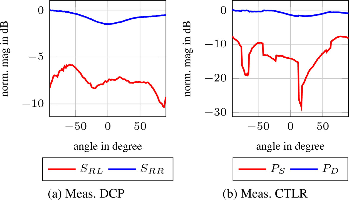
If single or double bounce is the only information which is desired, compact polarimetric approaches can be taken in consideration, too. Using DCP, the interpretation of measured values is straightforward regarding the differentiation of single and double bounces. Because circularly polarized waves change their sense of rotation at each bounce, it is sufficient to compare the amplitudes of the two receiving channels. The magnitude at the cross-polarized configuration  $S_{RL}$ represents the amount of single and odd bounces while the co-polarized channel
 $S_{RR}$ receives the power of double and even bounces, so no further calculations have to be executed. The two values of the target vector from equation (3) are plotted in Fig. 11(b) using the same measurement set-up as before.
Compact polarimetric approaches to distinguish single from double bounces. (a) Meas. DCP (b) Meas. CTLR.

This simple analysis is in contrast to the evaluation process of CTLR-mode. Using this compact polarimetric approach, desired ratios of even and odd bounces have to be calculated. In this contribution, the three-component compact decomposition proposed by Cloude et al. [Reference Cloude, Goodenough and Chen23] will be applied. Initially, the Stokes vector of the received signal has to be calculated. This can be done using the values of the corresponding target vector from equation (4) and the following equations.
 $$\eqalign{S_0 = & \vert S_{RH}\vert ^2 + \vert S_{RV}\vert ^2 \cr S_1 = & \vert S_{RH}\vert ^2-\vert S_{RV}\vert ^2 \cr S_2 = & 2 \Re(S_{RH}S_{RV}^{\ast}) \cr S_3 = & -2\Im(S_{RH}S_{RV}^{\ast}).}$$
In these equations,  $S_{kl}$ denotes the complex voltage in the subscripted combination of polarization, asterisks denote the complex conjugate and ℜ and ℑ the real and imaginary part of the value in brackets, respectively. The Stokes vector can be used to calculate the amount of the dihedral power
 $P_D$, the surface scattering power
 $P_S$ and the volume power
 $P_V$.
 $$\eqalign{P_D = & \displaystyle{{1} \over {2}} \left(\sqrt{S_1^2 + S_2^2 + S_3^2} + S_3\right) \cr P_S = & \displaystyle{{1} \over {2}}\left(\sqrt{S_1^2 + S_2^2 + S_3^2}-S_3\right) \cr P_V = & S_0-\sqrt{S_1^2 + S_2^2 + S_3^2}.} $$
The values of  $P_S$ and
 $P_D$ are plotted in Fig. 11(b) for the same measurements as before using a dihedral asa target witha varying angle in boresight direction.
Double bounce recognition
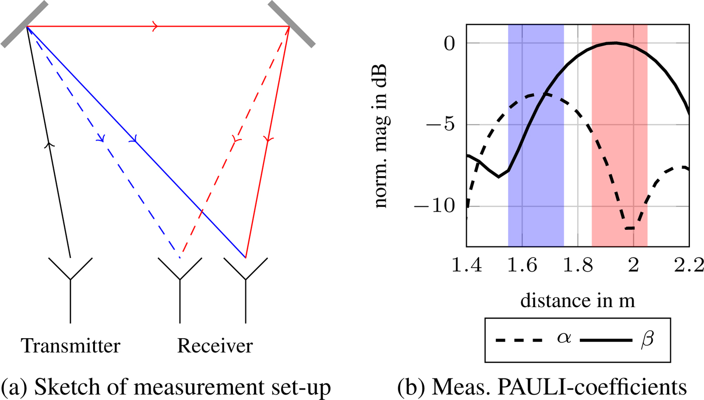
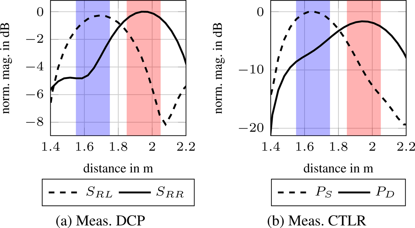
The recognition of double bounces is an issue in automotive applications which is mentioned frequently regarding false targets caused by additional reflections at crash barriers. Because these signals have been modified by a car or other moving targets, they are much harder to distinguish as signals reflected by stationary targets without a Doppler modification. Figure 12a shows a measurement set-up to create double bounce reflections and single bounce scatters. Two plates have been adjusted at  $\pm 10^\circ $ from boresight direction. In Fig. 12(b), in which the results of the Pauli-decomposition are plotted against the distance, the shorter single bounce path is highlighted with blue color and the longer double bounce path is marked in red color. The first Pauli coefficient, α is plotted dashed and reaches its maximum in the blue highlighted area while the second coefficient climaxes in the red area. Thus a separation of single and double bounces using the Pauli-decomposition is possible. Subsequent diagrams in Fig. 13 show the results gathered from the two compact polarimetric modes explained in the sections before. Again, solid lines represent the measured double bounce results and dashed lines the single bounce correspondents. As a separation in these diagrams is clearly visible, both compact polarimetric modes can be utilized in this field of application.
Sketch and measurement results of feasibility set-up for double bounce recognition using PAULI decomposition. (a) Sketch of measurement set-up (b) Meas. PAULI-coefficients.

Measurement results of feasibility set-up for double bounce recognition using DCP and CTLR. (a) Meas. DCP (b) Meas. CTLR.

Conclusion
A sensor system, which is able to perform compact polarimetric as well as full polarimetric measurements has been designed and put into operation successfully. The antennas, which were used to perform the polarized transceiving have been explained and the dielectric lens as the beam-forming component has been characterized. Measurements to characterize the radar system and to separate single from double bounces have been conducted with full polarimetric as well as the two compact polarimetric approaches DCP and CTLR. These led to good and comparable results in this chosen automotive scenario and further investigations are planned. One subsequent field of application is the characterization of surface textures particularly with respect to the classification of road conditions.
Acknowledgements
The authors would like to thank the European Regional Development Fund and the Ministry of Science, Research and the Arts of Baden-Württemberg, Germany, for financial funding via ZAFH MicroSens as well as Infineon Technologies, Munich, Germany for providing the SiGe-MMICs.
 Christian Erhart was born in Ulm, Germany, in 1987. He received his B.Sc. in Physical Engineering at the University of Applied Sciences Ravensburg-Weingarten. After completing his master degree in Electrical Engineering, he focused on polarimetric radar systems, doing his research at the University of Applied Sciences in Ulm. He is currently working towards his Ph.D. about building up classifiers using polarimetric backscattering from objects and surfaces.
 Steffen Lutz (S'2011-M'2015) was born in Ulm in 1986. He received his Bachelor in Mechatronics and his Master's degree in Systems Engineering in 2009, 2011, respectively. Afterward he worked as a research assistant at the Laboratory of Microtechnology of the University of Applied Sciences Ulm, where he focused on mm-wave MIMO radar system design. In 2015 he received his Ph.D. in electrical engineering from the University of Erlangen-Nuremberg and joined Airbus Defence and Space (meanwhile: Hensold Sensors) as radar system engineer. His research interests include system design for active and multi static passive radar systems and future trends in military radar and electronic warfare. He has authored and co-authored more than 20 technical reviewed papers and patents.
 Marc A. Mutschler received the B.Eng. degree in mechatronics from the University of Applied Sciences Ulm, Ulm, Germany, in 2013, and the M.Sc. degree in electrical engineering from the University of Ulm, Ulm, Germany, in 2016. Currently, he is pursuing the Dr.-Ing. degree at the University of Applied Sciences Ulm in cooperation with the department of Microwave Engineering of the University of Ulm. He is currently involved in research of cooperative Radar sensor systems and applications.
 Philipp A. Scharf received the M.Eng. degree in electrical engineering from Constance University of Applied Sciences, Constance, Germany, in 2015. Currently, he is working toward the Ph.D. degree at Ulm University of Applied Sciences in cooperation with the Institute of Microwave Engineering, Ulm University. His current research activities include frequency-dependent backscattering effects and multiband radar sensors.
 Thomas Walter was born 1963 in Sigmaringen / Germany. He received a diploma degree in electrical engineering from Stuttgart University in 1990. As a student, he was granted a scholarship from “Studienstiftung des deutschen Volkes”. During this time, he studied for 1 year at the University of Northumbria in Newcastle/GB. In 1995, he received his Ph.D. from Stuttgart University for research on electrical defects in thin film semiconductors. Afterward he joined Robert Bosch in Stuttgart working on microsystem technology, optical communication technology, and high-frequency electronics for automotive radars. During his R&D in industry, he was responsible for the introduction of SiGe-technology into 77 GHz radar sensors. In 2005, he joined the University of Applied Sciences Ulm (Germany) as a professor for microtechnology. He conducts several research projects on thin film solar cells and microwave sensors. In 2012, he was awarded the “Wissenschaftspreis der Stadt Ulm” for his research on microwave sensors.
 Hubert Mantz (born in 1976) studied Mathematics, Physics, and Computer Science at the University of Ulm, the Max Planck Institute for Metals Research, Stuttgart and the University of New York at Stony Brook, USA. He received a scholarship from the Cusanuswerk, the sponsorship organization of the German Bishops' Conference. He received his Ph.D. from Saarland University in Saarbrücken, Germany for studies about protein adsorption on substrates. During his subsequent industrial career at Carl Zeiss Microscopy, he was responsible for developing new detection mechanisms in electron microscopes as the project manager for analytics. More than 10 patents were granted to him from this topic. In 2011, he joined the University of Applied Sciences in Ulm. He specializes in the theory and application of physical measuring methods in various fields of application. Furthermore, he works on different research projects in the areas of radar sensors, E-mobility and fuel cell applications.
 Robert Weigel was born in Ebermannstadt, Germany, in 1956. He received the Dr.-Ing. and the Dr.Ing.habil. degrees, both in electrical engineering and computer science, from the Munich University of Technology in Germany where he respectively was a Research Engineer, a Senior Research Engineer, and a Professor for RF Circuits and Systems until 1996. During 1994–1995, he was a Guest Professor for SAW Technology at Vienna University of Technology in Austria. From 1996 to 2002, he has been Director of the Institute for Communications and Information Engineering at the University of Linz, Austria where, in August 1999, he co-founded the company DICE, meanwhile split into an Infineon Technologies (DICE) and an Intel (DMCE) company which are devoted to the design of RFICs for mobile radio and MMICs for vehicular radar applications. In 2000, he has been appointed a Professor for RF Engineering at the Tongji University in Shanghai, China. Since 2002 he is Head of the Institute for Electronics Engineering at the Friedrich-Alexander-University at Erlangen-Nürnberg, Germany. There, respectively in 2009, in 2012, and in 2015 he co-founded the companies eesy-id, eesy-ic and eesy-innovation.
Dr. Weigel has been engaged in research and development of microwave theory and techniques, electronic circuits and systems, and communication and sensing systems. In these fields, he has published more than 900 papers. He received the 2002 VDE ITG-Award, the 2007 IEEE Microwave Applications Award and the 2016 IEEE MTT-S Distinguished Educator Award.
Dr. Weigel is a Fellow of the IEEE, an Elected Member of the German National Academy of Science and Engineering (acatech), and an Elected Member of the Senate of the German Research Foundation (DFG). He is and has been serving on numerous advisory boards of government bodies, research institutes and companies in Europe and Asia. Furthermore, he is and has been serving on various editorial boards such as that of the Proceedings of the IEEE. He also has been founding editor of the Proceedings of the European Microwave Association (EuMA) which in 2008 where transformed into EuMAs International Journal of Microwave and Wireless Technologies. He has beena member of numerous conference steering and technical program committees. He was General Chair of several conferences such as the 2013 European Microwave Week in Nuremberg, Germany and Technical Program Chair of several conferences such as the 2002 IEEE International Ultrasonics Symposium in Munich, Germany. He served in many roles for the IEEE MTT and UFFC Societies. He has been Founding Chair of the Austrian COM/MTT Joint Chapter, Region 8 MTT-S Coordinator, Distinguished Microwave Lecturer, MTT-S AdCom Member, and the 2014 MTT-S President.