





1. Introduction
The impact of a liquid drop on a solid target has been extensively studied (Yarin Reference Yarin2006; Josserand & Thoroddsen Reference Josserand and Thoroddsen2016; Yarin, Roisman & Tropea Reference Yarin, Roisman and Tropea2017) since Worthington's pioneering observations (Worthington Reference Worthington1877). The dynamics of the spreading liquid can now be described using analytical expressions once the drop touches the substrate (Gordillo, Riboux & Quintero Reference Gordillo, Riboux and Quintero2019). The initial stage of spreading is governed by inertia so that the wetted radius follows Wagner's theorem (Riboux & Gordillo Reference Riboux and Gordillo2014). Later, viscous and capillary forces oppose the outwards motion and ultimately balance the initial inertia as the maximal radius is reached (Laan et al. Reference Laan, de Bruin, Bartolo, Josserand and Bonn2014; Wildeman et al. Reference Wildeman, Visser, Sun and Lohse2016). Yet, before spreading starts, the air trapped between the falling drop and the substrate must drain for contact to occur. This phase, during which the drop levitates on an air cushion, can affect the outcome of impact as revealed by the dramatic influence of ambient pressure on splashing (Xu, Zhang & Nagel Reference Xu, Zhang and Nagel2005; Driscoll & Nagel Reference Driscoll and Nagel2011). This levitation phase can even dominate and last during the whole impact for low impact velocities (Kolinski, Mahadevan & Rubinstein Reference Kolinski, Mahadevan and Rubinstein2014a). This holds even more when the substrate is heated far above the boiling point of the liquid, as then the impacting drop is separated from the substrate by a cushion of its own vapour, a situation called the dynamic Leidenfrost effect (Tran et al. Reference Tran, Staat, Prosperetti, Sun and Lohse2012).
The Leidenfrost effect (Leidenfrost Reference Leidenfrost1756; Quéré Reference Quéré2013) has received a lot of attention owing to its relevance in heat transfer applications such as spray cooling (Kim Reference Kim2007; Breitenbach, Roisman & Tropea Reference Breitenbach, Roisman and Tropea2018), the cooling of fuel rods in case of a nuclear incident (Hamdan, Kim & Moon Reference Hamdan, Kim and Moon2015) or spray combustion (Moreira, Moita & Panao Reference Moreira, Moita and Panao2010). As the presence of gas between the liquid and the solid dramatically reduces the heat flux, phase diagrams distinguishing levitation and contact behaviours have been obtained for many liquid–solid combinations based on side-view imaging (Yao & Cai Reference Yao and Cai1988; Bernardin & Mudawar Reference Bernardin and Mudawar2004) and, more recently, on the direct bottom-view observation of contact (Tran et al. Reference Tran, Staat, Prosperetti, Sun and Lohse2012; Staat et al. Reference Staat, Tran, Geerdink, Riboux, Sun, Gordillo and Lohse2015; Shirota et al. Reference Shirota, van Limbeek, Sun, Prosperetti and Lohse2016). Understanding the dynamics of the air and vapour film (together referred to as gas from now on) trapped at impact on superheated substrates is thus key to predicting the heat transfer.
When the liquid and the solid are both at ambient temperature, the drainage of the air film trapped between the falling drop and the substrate has been thoroughly investigated. In this situation, that we call an isothermal impact, the pressure buildup under the drop results in the formation of a dimple whose edge is marked by a localized region of high curvature, called the neck (Mandre, Mani & Brenner Reference Mandre, Mani and Brenner2009; Hicks & Purvis Reference Hicks and Purvis2010; Mani, Mandre & Brenner Reference Mani, Mandre and Brenner2010; Bouwhuis et al. Reference Bouwhuis, van der Veen, Tran, Keij, Winkels, Peters, van der Meer, Sun, Snoeijer and Lohse2012). This region eventually moves downwards, leading either to the wetting of the substrate and the entrapment of an air bubble (Chandra & Avedisian Reference Chandra and Avedisian1991; Thoroddsen et al. Reference Thoroddsen, Etoh, Takehara, Ootsuka and Hatsuki2005), or, for low enough impact velocities and sufficiently smooth substrates, to the creation of a relatively flat air film that can enable drop bouncing (Kolinski et al. Reference Kolinski, Mahadevan and Rubinstein2014a). In the latter case, the dimple and neck have a fixed radial position and height as the liquid spreads (Kolinski et al. Reference Kolinski, Rubinstein, Mandre, Brenner, Weitz and Mahadevan2012; Kolinski, Mahadevan & Rubinstein Reference Kolinski, Mahadevan and Rubinstein2014b). For impacts on superheated substrates, however, it is yet unclear how evaporation contributes to the evolution of the gas film, although it is already known that the dimple and neck structure also appears (Shirota et al. Reference Shirota, van Limbeek, Sun, Prosperetti and Lohse2016).
In this article, we aim to disentangle the effects of gas drainage and vapour generation on the short-time drop impact dynamics to provide insight into the transition from drop levitation to contact. In order to do so, we probed the dynamics of the gas layer squeezed between the liquid and the substrate at impact and monitored the failure of the gas film. We observed hitherto unreported vertical oscillations of the drop bottom interface, specific to superheated conditions, that can trigger contact events. We thus seek to understand the role of these oscillations on the transition towards the dynamic Leidenfrost effect. The experimental set-up and procedure are detailed in § 2. In § 3, we discuss the evolution of the film shape at short times and the influence of surface temperature on its characteristic features. We also report the measurements of the minimum thickness at short times and provide a model to account for them. In § 4, the transition from levitation to contact is discussed, based on identifying the type of collapse of the gas layer in the parameter space spanned by the surface temperature and the impact velocity. Finally, we model the vertical oscillations of the drop's base and discuss their role in the transition towards the dynamic Leidenfrost effect. The paper ends with conclusions and an outlook (§ 5).
2. Experimental set-up and procedure
Our experiments, sketched in figure 1, consist of impacting ethanol drops (with density  $\rho_l$, viscosity
 $\eta_l$ and surface tension
 $\gamma$) on an optically smooth sapphire disk. We chose this liquid–solid combination as (i) it allows us to neglect vapour cooling effects during impact and (ii) the excellent thermal conductivity of sapphire (
 $k_s = 35$ W K
 $^{-1}$ m
 $^{-1}$) approximates isothermal substrate conditions (Van Limbeek et al. Reference Van Limbeek, Shirota, Sleutel, Sun, Prosperetti and Lohse2016, Reference Van Limbeek, Schaarsberg, Sobac, Rednikov, Sun, Colinet and Lohse2017). The sapphire substrate is coupled to a glass dove prism using silicone oil and mounted in an aluminium heating block. The substrate temperature
 $T_s$ is set to a fixed value between
 $105\,^\circ$C and
 $270\,^\circ$C using a proportional-integral-derivative controller, and measured with an external surface probe. From this, we deduce the superheat
 $\Delta T = T_s - T_b$, where
 $T_b = 78\,^\circ$C is the boiling temperature of ethanol. Drops with radius
 $R = 1.0 \pm 0.1$ mm are released from a calibrated needle, whose height is adjusted to obtain impact velocities
 $U$ ranging from 0.3 to 1.2 m s
 $^{-1}$. The chosen drop radii and impact velocities correspond to a Reynolds number
 ${\textit {Re}} = \rho _l R U/\eta _l$ and an Ohnesorge number
 ${\textit {Oh}} = \eta _l/\sqrt {\rho _l R \gamma }$, with typical values of 500 and 0.01, respectively, i.e. initially viscous effects can be neglected compared with inertia and capillarity. The Weber number
 ${\textit {We}} = \rho _l RU^2/\gamma$, ranging from 3 to 50, further indicates that experiments are conducted in the inertial regime, as evidenced by Bouwhuis et al. (Reference Bouwhuis, van der Veen, Tran, Keij, Winkels, Peters, van der Meer, Sun, Snoeijer and Lohse2012) in their study of dimple formation. Table 1 gives an overview of the properties of the liquid and of the two components of the gas phase: air (with ambient temperature
 $T_a$) and ethanol vapour. Note that the material properties of the fluids are temperature dependent (see Appendix A) and the temperature at which they should be evaluated will be discussed throughout the manuscript.
Ethanol drops with equilibrium radius  $R$ and velocity
 $U$ impact a heated sapphire substrate with temperature
 $T_s$. We record side views and use reflection interference (RI) and total internal reflection (TIR) imaging to measure the thickness of the gas film squeezed between the liquid and the solid with three synchronized high-speed cameras. We define in the sketch the dimple and neck height,
 $h_d$ and
 $h_n$, respectively, as well as the radial extent of the neck region
 $\ell$ (sketch not to scale).

Physical properties of ethanol in the liquid (l) and vapour (v) phase and of air.

We study the impact dynamics using three synchronized high-speed cameras to obtain side views and interferometric measurements of the gas film (figure 1). We record side views at 20 000 frames per second (Photron Fastcam SA1.1) from which we determine the drop radius  $R$ and the impact velocity
 $U$. We measure the gas film thickness profile by coupling two interferometry techniques that have been successfully applied in the context of drop impact: single-wavelength reflection interference (RI) (Driscoll & Nagel Reference Driscoll and Nagel2011; Li & Thoroddsen Reference Li and Thoroddsen2015; Staat et al. Reference Staat, Tran, Geerdink, Riboux, Sun, Gordillo and Lohse2015) and total internal reflection (TIR) imaging (Kolinski et al. Reference Kolinski, Rubinstein, Mandre, Brenner, Weitz and Mahadevan2012; Shirota et al. Reference Shirota, van Limbeek, Sun, Prosperetti and Lohse2016). Simultaneously using these two techniques allows us to realize the benefits of both of them: RI enables relative thickness measurements of thin films up to tens of micrometres while TIR imaging provides an absolute information on the evanescent length scale of the order of 100 nm. The combination of both techniques gives access to the absolute thickness of the entire profile of the gas layer during drop impact.
We implement these two techniques simultaneously by expanding a diode laser spot with wavelength  $\lambda = 643$ nm into a collimated beam that we split into two optical paths leading to the substrate. The beam used for RI imaging is introduced through the bottom face of the dove prism at a slight angle to only observe interferences generated by reflections at the top of the substrate and the bottom of the drop. The interference patterns are composed of dark and bright fringes that we image using a long distance microscope (Navitar telecentric 12
 $\times$) mounted on a high-speed camera (Photron SA-Z) to obtain a typical resolution of 8
 $\mathrm {\mu }$m px
 $^{-1}$ at a frame rate of 700 000 frames per second. The TIR beam is p-polarized and introduced through one of the sloped faces of the prism so that it undergoes TIR at the top of the substrate. The interaction of the emitted evanescent wave and the impinging drop results in a decrease of the reflected intensity that enables the measurement of the film thickness. When the drop touches the surface, light transmits through the liquid creating a sharp change in grey scale intensity that allows us to distinguish wetted from dry areas. The resulting images are recorded at 225 000 frames per second (Photron Nova S12) with a long distance microscope with resolution
 $10\,\mathrm {\mu }$m px
 $^{-1}$. The details of image processing and calibration of interferometric measurements are further discussed in Appendix B.
3. Short-time dynamics of the gas film
Side views of the impact event of an ethanol drop in the dynamic Leidenfrost regime are presented in figure 2(a) ( $U = 0.5$ m s
 $^{-1}$,
 ${\textit {We}} = 9.9$ and
 $T_s = 164\,^\circ$C). The impinging liquid spreads, recoils and finally detaches from the substrate after a time of the order of 10 ms. This time, that we call the rebound time, is set by the inertio-capillary time scale
 $\tau _c = \sqrt {\rho _lR^3/\gamma }$ (Richard, Clanet & Quéré Reference Richard, Clanet and Quéré2002; Biance et al. Reference Biance, Chevy, Clanet, Lagubeau and Quéré2006). Here, we define the origin of time (
 $t=0$) as the time of the first frame where the drop enters within the evanescent length scale. We focus on the dynamics of the gas film squeezed between the liquid and the hot substrate at the first instant of impact, that is for
 $0 < t < \tau _i$ where
 $\tau _i = R/U$ is the inertial time scale. For a drop with radius 1 mm impacting at 1 m s
 $^{-1}$, this inertial time is
 $\tau _i = 1$ ms and therefore much shorter than the inertio-capillary time
 $\tau _c \approx 10$ ms.
(a) Side-view snapshots of the impact of an ethanol drop ( $R = 1.1$ mm,
 $U = 0.5$ m s
 $^{-1}$ and
 ${\textit {We}} = 9.9$) on a substrate heated at
 $T_s = 164\,^\circ$C. The liquid detaches after 18.1 ms. Note that the side view is recorded at a slight angle from the horizontal. (b) Short-time TIR snapshots taken during the impact pictured in (a). The origin of time (
 $t=0$) is chosen as the first frame where the liquid enters within the evanescent length scale. The original grey scale image and reconstructed height field with a cutoff height of 800 nm are shown. (c) Synchronized RI snapshots showing approximately one fourth of the drop's bottom interface. Videos (S1–S2) are in the supplementary material available at https://doi.org/10.1017/jfm.2021.843.

3.1. Phenomenology
3.1.1. Sequence of events
In figure 2(b,c), we present synchronized TIR (figure 2b) and RI (figure 2c) images recorded during the first instants of the impact presented in figure 2(a). The TIR snapshots combine the original grey scale image and the calculated height field colour map. The liquid first enters within the evanescent length scale as a faint ring ( $t = 0.018$,ms). This ring expands as its height decreases, indicating that the liquid comes closer to the substrate as it starts spreading (
 $t = 0.035$ ms). The full film profile can be inferred by combining the information extracted from TIR with the axisymmetric interference patterns observed in RI images. The brightest fringes are localized at the same radial position as the TIR ring evidencing the region closest to the substrate which is called the neck. The liquid–air interface displays a dimple shape, sketched in the inset, as already observed in both isothermal and superheated conditions (Shirota et al. Reference Shirota, van Limbeek, Sun, Prosperetti and Lohse2016). Eventually, the whole bottom interface of the drop moves away from the substrate and escapes from the TIR measurement range (
 $t = 0.28$ ms) while we continue to observe the spreading liquid as the RI fringe pattern remains visible.
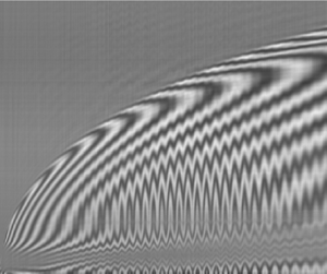
Combining TIR and RI, we are able to visualize the dynamics of the whole gas layer and to compare them with their isothermal counterpart. We azimuthally average each RI and TIR snapshot and stack the one-dimensional information obtained at each instant in space–time two-dimensional graphs (figures 3(a) and 3(b)). From this representation, we are able to distinguish three phases in the early evolution of the squeezed film:
(i) The initial approach during which the liquid–gas interface first deforms, creating the central dimple bordered by a region of high curvature (see the first profile of the liquid–gas interface,
 $\Delta t = 0$ ms, in figure 3c). This region, which is called the neck region, moves down and outwards until the minimum thickness is reached at the neck, here at $t = 0.031$ ms, marking the end of this first phase. During this initial phase, the motion of the liquid–gas interface is qualitatively similar to that reported in the absence of substrate heating (Mandre et al. Reference Mandre, Mani and Brenner2009; Hicks & Purvis Reference Hicks and Purvis2010; Mani et al. Reference Mani, Mandre and Brenner2010; Bouwhuis et al. Reference Bouwhuis, van der Veen, Tran, Keij, Winkels, Peters, van der Meer, Sun, Snoeijer and Lohse2012).
(ii) A second phase, for
$0.031 < t<0.4$ ms, in which the centre of the dimple and the neck have markedly different vertical motion. The thickness at the centre ($r=0$) is constant, as evidenced by the absence of crossings between iso-height lines (i.e. fringes) and the centreline in figure 3(a). In the same time interval, the neck thickness increases, as shown by the TIR data (figure 3b) and by the multiple crossings between the dashed red line, materializing the neck location, and iso-height lines in figure 3(a). Here, the radial and upwards motion of the neck allows us to distinguish the superheated from the isothermal case where the neck has a fixed radial position and height (Kolinski et al. Reference Kolinski, Rubinstein, Mandre, Brenner, Weitz and Mahadevan2012, Reference Kolinski, Mahadevan and Rubinstein2014b).(iii) In the final phase (
$t>0.4$ ms), both the thickness at the centre and at the neck increase as the liquid keeps spreading. This global film thickness increase, which occurs at different instants at the neck and at the dimple, further differentiates the hot and the cold case and is characteristic of the influence of vapour generation.


(a,b) Space–time plots of the short-time film dynamics obtained by azimuthally averaging the RI and TIR snapshots for the impact shown in figure 2(a) ( $R = 1.1$ mm,
 $U = 0.5$ m s
 $^{-1}$,
 ${\textit {We}} = 9.9$ and
 $T_s = 164\,^\circ$C). The dashed lines in (a,b) and (d,e) are a guide to the eye indicating the position of the neck extracted from the RI space–time plots. (c) Successive liquid–gas profiles extracted from (b). The colour code stands for the time difference from the instant at which the minimum thickness is reached. (d,e) Space–time plots obtained for similar impact parameters as in (a,b) (
 $R = 1.0$ mm,
 $U = 0.48$ m s
 $^{-1}$ and
 ${\textit {We}} = 8.3$) but with
 $T_s = 105\,^\circ$C. ( f) Successive height profiles extracted from (e). The colour code is the same as in (c). Video (S3) is available in the supplementary material.

3.1.2. Recovering the isothermal behaviour
We observe the transition from the superheated to the isothermal behaviour by performing impacts on substrates heated just above the boiling temperature of ethanol. For similar impact parameters as in figure 2(a) ( $U = 0.48$ m s
 $^{-1}$,
 ${\textit {We}} = 8.3$) but with
 $T_s = 105\,^\circ$C, the liquid–gas interface transiently forms a wide flat region that is closer to the substrate (figure 3e), while the dimple shape remains frozen, as shown by the horizontal fringes in figure 3(d): we recover the film shape reported for isothermal conditions (Kolinski et al. Reference Kolinski, Mahadevan and Rubinstein2014b). The collapse of the successive height profiles at the neck region plotted in figure 3( f) illustrates the transition from a neck sweeping motion (figure 3c) to a quasi-invariant film shape with decreasing superheat. The growth of the thickness at the neck and, later, at the centre indicates that vapour is still generated and distinguishes this case from the isothermal impact.
We now seek to quantitatively characterize the effect of the superheat on the gas layer. To do so, we describe the neck motion and measure the film thickness at the neck and at the centre, when there is no liquid–solid contact at short time, for different superheats and impact velocities.
3.2. Neck dynamics
We track the azimuthally averaged neck radius  $r_n(t)$ (figure 4a) and distance to the substrate (i.e. neck height)
 $h_n(t) = h(r_n(t),t)$ (figure 4b) for varying impact velocities and substrate temperatures at short times. As the neck spreads, its height decreases, with a velocity
 $\textrm {d} h_n/\textrm {d} t$ of the order of the impact velocity, until it reaches a minimum value
 $h_m$ that corresponds to the global minimum of the azimuthally averaged gas layer thickness. Later, the neck height grows at a slower rate. The evolution of
 $r_n(t)$ seems to be only affected by the impact velocity. In contrast, the neck height
 $h_n(t)$ is strongly influenced also by the substrate temperature
 $T_s$. This behaviour suggests that the spreading dynamics evidenced for isothermal impacts (Rioboo, Marengo & Tropea Reference Rioboo, Marengo and Tropea2002; Mongruel et al. Reference Mongruel, Daru, Feuillebois and Tabakova2009; Thoroddsen, Takehara & Etoh Reference Thoroddsen, Takehara and Etoh2012) could describe the neck motion. Notably, the Wagner prediction,
 $r_n(t) = \sqrt {3URt}$, shown to be accurate for the radius of the liquid–solid contact by Riboux & Gordillo (Reference Riboux and Gordillo2014) and Gordillo et al. (Reference Gordillo, Riboux and Quintero2019) on cold surfaces and by Shirota et al. (Reference Shirota, van Limbeek, Sun, Prosperetti and Lohse2016) on superheated substrates, could also be relevant in the levitated regime. We indeed observe a good agreement of that prediction with the data by plotting the normalized neck radius
 $r_n/R$ as a function of the dimensionless time
 $tU/R$ for three different impact velocities and superheats (figure 4c). The data collapse, in quantitative agreement with Wagner's prediction represented by the solid line. We conclude that vapour generation strongly affects the vertical motion of the liquid–gas interface at the neck, but has negligible influence on its horizontal dynamics.
(a) Time evolution of the azimuthally averaged neck radius  $r_n(t)$ for varying impact velocities
 $U$ and substrate temperatures
 $T_s$. The data are extracted from TIR images such as figure 3(b). The solid lines represent predictions from the Wagner theory,
 $r_n(t) = \sqrt {3URt}$. (b) Azimuthally averaged height at the neck
 $h_n(t)$ at short time. We denote
 $h_m$ the azimuthally averaged minimum film thickness. (c) Normalized azimuthally averaged neck radius
 $r_n/R$ as a function of the dimensionless time
 $tU/R$. The solid line shows the Wagner prediction. (d) Central dimple height
 $h_d$ plotted as a function of
 $U$ for the impact of drops for various
 $T_s$. Note that
 $h_d$ has a non-monotonic dependence on
 $T_s$. The solid line corresponds to the scaling
 $h_d/R \sim {\textit {St}}^{-2/3}$, taking the viscosity of the gas,
 $\eta _{g}$, as the viscosity of air at 20
 $^\circ$C. The dashed and dotted lines correspond to two limiting choices for the gas viscosity, that of air at 230
 $^\circ$C, and that of ethanol vapour at
 $T_b$, respectively. The square symbols are obtained in cases in which the liquid touches the solid. (e) Minimum film thickness
 $h_m$ as a function of the impact speed
 $U$ for various
 $T_s$. The dashed lines are guides to the eye with a slope of
 $-2$. ( f) Normalized minimum film thickness
 $h_m/R$ as a function of the prediction of (3.21), the data are consistent with this prediction and a fit gives a prefactor of
 $4.0 \pm 0.2$ in (3.21).

3.3. Thickness at the dimple and the neck
We now focus on the effect of  $T_s$ on the thickness of the gas film. In figure 4(d), we show the dimple height
 $h_d$ measured at the same instant as the minimum thickness
 $h_m$ is reached and, for the two lowest substrate temperatures, also at the instant when contact occurs at the neck (square markers), enabling us to probe velocities up to 2 m s
 $^{-1}$. We obtain
 $h_d$ as the sum of the thickness at the neck
 $h_m$, determined using TIR, and of the height difference between the dimple and the neck, which we extract from the RI monochromatic fringe pattern. Coupling these two techniques, we are not limited by the 800 nm cutoff height and observe dimple heights of the order of 1 to 5
 $\mathrm {\mu }$m, decreasing with increasing impact velocity. We compare our measurements with the scaling relation for
 $h_d$ derived in the absence of heating,
 $h_d/R \sim {\textit {St}}^{-2/3}$, where
 ${\textit {St}} = \rho _lRU/\eta _g$ is the Stokes number (Mandre et al. Reference Mandre, Mani and Brenner2009; Mani et al. Reference Mani, Mandre and Brenner2010; Bouwhuis et al. Reference Bouwhuis, van der Veen, Tran, Keij, Winkels, Peters, van der Meer, Sun, Snoeijer and Lohse2012), and
 $\eta _g$ the viscosity of the gas layer. Note that we define the Stokes number as the inverse of that proposed by Mandre et al. (Reference Mandre, Mani and Brenner2009) but consistent with other publications on the subject. The data are compatible with the isothermal scaling: for a fixed superheat
 $\Delta T$ and drop radius
 $R$, the dimple height decrease with increasing impact velocity
 $U$ is consistent with a power-law behaviour with an exponent
 $-2/3$. Yet, we observe a weak influence of the substrate temperature on
 $h_d$ that has a non-monotonic dependence with increasing superheat.
In figure 4(e), we show the minimum distance  $h_m$ separating the drop from the substrate as a function of the control parameters
 $U$ and
 $T_s$. This minimum distance is of the order of a few hundred nanometres, and strongly increases with the superheat, in contrast to the weak non-monotonic influence observed for
 $h_d$. For example, increasing
 $T_s$ from 178 to 230
 $^\circ$C leads to a doubling of the thickness at the neck for
 $U = 0.7$ m s
 $^{-1}$. For a fixed substrate temperature and drop radius, the data suggest a power-law decrease of
 $h_m$ with the impact velocity
 $U$ with an exponent
 $-2 \pm 0.2$. This exponent is close to that predicted for the minimum thickness at the neck in the isothermal case
 $-20/9$ (Mandre et al. Reference Mandre, Mani and Brenner2009; Mani et al. Reference Mani, Mandre and Brenner2010), but the strong influence of
 $\Delta T$ evidences the role of evaporation and distinguishes this case from an impact on a substrate at ambient temperature .
3.4. Model for the initial approach
We now seek to model the initial approach, i.e. the evolution of the gas film until the minimum thickness is reached at the neck. Typically, this phase lasts until  $tU/R < 0.01$, a time much shorter than that associated with the purely inertial spreading that is valid up to
 $tU/R < 0.1$. We build on the work of Mani et al. (Reference Mani, Mandre and Brenner2010), who treated the case of isothermal impacts, and extend it to take into account the effect of vapour production. Indeed, our measurements of the dimple thickness in superheated conditions show the same scaling relation with the Stokes number as for isothermal impacts, indicating that liquid inertia and viscous drainage are still the relevant mechanisms when the substrate is heated. Yet, the thickness at the neck strongly depends on the superheat, suggesting that, to describe the movement of the liquid–gas interface, one also needs to capture the influence of vapour generation.
For completeness, we reproduce the equations of motion for the liquid and for the gas film in the incompressible regime as already derived by Mani et al. (Reference Mani, Mandre and Brenner2010). Following them, we consider a two-dimensional geometry and make further simplifications as in the isothermal case: in the liquid, we neglect viscosity and nonlinear inertia owing to, respectively, the large Reynolds number ( ${\textit {Re}} = \rho _l R U/\eta _l = 330$ for the impact of a millimetre-sized drop at
 $U = 0.5$ m s
 $^{-1}$) and the absence of velocity gradients within the drop before it interacts with the substrate. We also neglect the influence of surface tension, as for a typical impact the Weber number,
 ${\textit {We}} \approx 10$, is considerably larger than unity. With these assumptions, we have potential flow in the liquid and the equation of motion reads
 \begin{equation} \rho_l \frac{\partial\boldsymbol{u}}{\partial t} + \boldsymbol{\nabla} p_l = 0,\quad \boldsymbol{\nabla}\boldsymbol{\cdot} \boldsymbol{u} = 0, \end{equation}
where  $\boldsymbol {u} = (u,v)$ are the liquid velocity components in the
 $x$ (replacing
 $r$ in this two-dimensional model) and
 $z$ directions, respectively, and
 $p_l$ is the liquid pressure. Projecting (3.1a,b) in the vertical direction and using the kinematic boundary condition at the liquid–gas interface
 $\partial h/\partial t = v - u \partial h/\partial x$, we obtain at
 $z=0$
 \begin{equation} \rho_l \frac{\partial^2 h }{\partial t^2} + \frac{\partial p_l}{\partial z} ={-} \rho_l \frac{\partial}{\partial t}\left(u\frac{\partial h}{\partial x}\right), \end{equation}
where, in the spirit of the boundary layer approximation (Prandtl Reference Prandtl1904), the term on the right-hand side can be neglected. Then, the vertical pressure gradient at the interface can be expressed as the Hilbert transform of the horizontal pressure gradient by taking advantage of the two-dimensional nature of the problem and the harmonic pressure field (Smith, Li & Wu Reference Smith, Li and Wu2003)
 \begin{equation} \rho_l \frac{\partial^2 h }{\partial t^2} -\mathcal{H}\left[\frac{\partial p_l}{\partial x}\right] = 0. \end{equation}
We now come to the description of the gas flow between the drop and the substrate. Here, the viscous lubrication approximation is justified as the gas film is thin ( $h \ll R$) and the typical value of the Reynolds number is low in the gas phase (
 ${\textit {Re}} = \rho _g h_d U/\eta _g = 0.05$ for air at 20
 $^\circ$C). This approximation is valid when considering heating as the value of the Reynolds number is not significantly altered by the presence of ethanol vapour (
 ${\textit {Re}} = \rho _v h_d U/\eta _v = 0.15$ for ethanol vapor at
 $T_b$), nor by the dependence of the gas viscosity and density on temperature. With these assumptions, we obtain the lubrication equation
 \begin{equation} \frac{\partial h}{\partial t} - \frac{\xi}{12 \eta_g}\frac{\partial}{\partial x} \left(h^3 \frac{\partial p_g}{\partial x}\right) = 0, \end{equation}
where  $\xi$ is a numerical coefficient which accounts for the choice of boundary condition at the liquid–gas interface. If the no-slip condition holds at the interface,
 $\xi = 1$. In contrast, if a zero tangential stress condition is chosen,
 $\xi =4$ (Guyon, Hulin & Petit Reference Guyon, Hulin and Petit2012).
We now introduce an additional term in the lubrication equation to take into account the effect of evaporation. We consider that heat is transferred through the gas layer by conduction, similarly as in the static Leidenfrost situation, as this mechanism acts on a relevant time scale for impact,  $h^2/\kappa _v \approx 0.1\,\mathrm {\mu }$s, much shorter than the initial approach time. The energy input from the heated solid is used to heat liquid at the bottom interface from the ambient temperature
 $T_a$ to the boiling temperature
 $T_b$, creating a thermal boundary layer with thickness
 $\sqrt {\kappa _l t}$, and to vaporize it. The Jakob number
 $Ja = C_{p,l}(T_b - T_a)/\mathcal {L}$, which compares the sensible heat with the latent heat
 $\mathcal {L}$, is
 $0.16$ so that we consider the energetic cost coming from the latent heat to be dominant. With this assumption, which overestimates the vapour production, the evaporation rate per unit area,
 $e$, is given by balancing the heat flux
 $k_g\Delta T/h$ with the released latent heat
 $\mathcal {L}e$, yielding
 $e = k_g\Delta T/(\mathcal {L}h)$. We thus obtain a modified lubrication equation
 \begin{equation} \frac{\partial h}{\partial t} - \frac{\xi}{12 \eta_g}\frac{\partial}{\partial x} \left(h^3 \frac{\partial p_g}{\partial x}\right) = \frac{1}{\rho_g}\frac{k_g \Delta T}{\mathcal{L}h}, \end{equation}
where the term on the right-hand side takes into account evaporation (Biance, Clanet & Quéré Reference Biance, Clanet and Quéré2003; Sobac et al. Reference Sobac, Rednikov, Dorbolo and Colinet2014).
3.4.1. Dimple height
Having obtained the governing equations for the liquid and the gas, we recall the dimple height scaling derived for isothermal impacts (Mani et al. Reference Mani, Mandre and Brenner2010; Bouwhuis et al. Reference Bouwhuis, van der Veen, Tran, Keij, Winkels, Peters, van der Meer, Sun, Snoeijer and Lohse2012). It is obtained by balancing liquid inertia with viscous drainage in the squeezed gas film. The pressure in the liquid can be estimated from (3.2) or (3.3)
 \begin{equation} p_l/L \sim \rho_l U^2/h_d, \end{equation}
where  $L \sim \sqrt {h_dR}$ is the radial extent of the dimple computed as the radius of a spherical cap with height
 $h_d$. The gas pressure is deduced from the two-dimensional incompressible lubrication equation (3.4)
 \begin{equation} p_gh^3/\eta_gL^2 \sim U. \end{equation}
The dimple height is set when the liquid–gas interface first deforms, that is when the pressure in the liquid and in the gas become comparable
 \begin{equation} h_d \sim R\left(\frac{\eta_g}{\rho_lRU}\right)^{2/3} \sim R {\textit{St}}^{{-}2/3}, \end{equation}
where  ${\textit {St}} = \rho _lRU/\eta _g$ is the Stokes number. The solid line (figure 4d) represents (3.8) with
 $\eta _g$ taken as the viscosity of air at 20
 $^\circ$C and a prefactor of 2.8 extracted from the results of Bouwhuis et al. (Reference Bouwhuis, van der Veen, Tran, Keij, Winkels, Peters, van der Meer, Sun, Snoeijer and Lohse2012) for the impact of ethanol drops on a substrate at room temperature. The isothermal scaling gives a correct order of magnitude of
 $h_d$ and recovers the velocity dependence in superheated conditions, confirming that the viscous drainage of the gas layer dominates vapour generation as suggested by the weak influence of substrate temperature on the dimple height in our experiments.
We propose to explain the observed influence of  $T_s$ also through (3.8), although it does not explicitly involve temperature. Indeed,
 $\eta _g$ depends on temperature in two ways. (i) The viscosity of the air squeezed between the drop and the surface increases with
 $T_s$, and (ii) as ethanol vapour is generated, the squeezed layer becomes a – possibly non-homogeneous – mixture of warm air and ethanol vapour, whose viscosity is lower than that of air at the same temperature. The interplay between these two antagonistic effects could be the cause of the non-monotonic behaviour of
 $h_d$ with
 $T_s$. In figure 4(d), we plot the scalings associated with each effect by taking
 $\eta _g$ as the viscosity of air at 230
 $^\circ$C (dashed line) and as the viscosity of ethanol vapour at the boiling point (dotted line): all measurements lie in between the two bounds.
3.4.2. Neck thickness
We next focus on the subsequent formation of the neck. Here, we extend the calculation of Mani et al. (Reference Mani, Mandre and Brenner2010) to incorporate the effect of evaporation, as our experimental observations show a strong influence of the substrate temperature on the thickness at the neck. We non-dimensionalize the governing equations (3.3) and (3.5) with the scales involved in the dimple formation, namely with the transformations
 \begin{align} h = R {\textit{St}}^{{-}2/3}\tilde{h},\quad x = R {\textit{St}}^{{-}1/3}\tilde{x},\quad t = \frac{R {\textit{St}}^{{-}2/3}}{U}\tilde{t}, \quad p_l = \frac{\eta_g U}{R {\textit{St}}^{{-}4/3}}\tilde{p}_l, \quad p_g = P_0 \tilde{p}_g, \end{align}
where  $P_0$ is the atmospheric pressure. Then, the equations of motion of the liquid and gas respectively become
 $$\begin{gather} \frac{\partial^2 \tilde{h}}{\partial \tilde{t}^2} - \varepsilon \mathcal{H}\left[ \frac{\partial \tilde{p}_l}{\partial \tilde{x}}\right] = 0, \end{gather}$$
 $$\begin{gather}\frac{\partial \tilde{h}}{\partial \tilde{t}} - \delta \frac{\xi}{12}\frac{\partial}{\partial \tilde{x}}\left(\tilde{h}^3\frac{\partial \tilde{p}_g}{\partial \tilde{x}}\right) = \frac{\mathcal{E}{\textit{St}}^{5/3}}{{\textit{We}} \tilde{h}}. \end{gather}$$
Here, we have introduced two extra dimensionless quantities:
(i) the ratio of the atmospheric pressure to the pressure build-up below the drop,
(3.12)\begin{equation} \delta = \frac{P_0 RSt^{{-}4/3}}{\eta_gU}; \end{equation}(ii) and the evaporation number
$\mathcal {E}$ defined by Sobac et al. (Reference Sobac, Rednikov, Dorbolo and Colinet2014) in the study of static Leidenfrost drops,
(3.13)\begin{equation} \mathcal{E} = \frac{\eta_g k_g \Delta T}{\gamma \rho_g R \mathcal{L}}. \end{equation}


The pressure buildup in the gas film below the drop is a small correction to the atmospheric pressure. We thus consider the limit  $\delta \gg 1$, that is the incompressible limit, and assume the following pressure expansion
 $\tilde {p}_g = 1 + \tilde {p}/\delta$ which we introduce in the governing equation:
 \begin{equation} \frac{\partial^2 \tilde{h}}{\partial \tilde{t}^2} - \mathcal{H}\left[ \frac{\partial \tilde{p}}{\partial \tilde{x}}\right] = 0,\quad \frac{\partial \tilde{h}}{\partial \tilde{t}} - \frac{\xi}{12}\frac{\partial}{\partial \tilde{x}} \left(\tilde{h}^3\frac{\partial \tilde{p}}{\partial \tilde{x}}\right) = \frac{\mathcal{E}{\textit{St}}^{5/3}}{{\textit{We}} \tilde{h}}, \end{equation}
where we used the pressure continuity at the interface (i.e.  $p_g = p_l$). As the motion of the liquid–gas interface is similar in the isothermal and the superheated cases, we adopt the same self-similar ansatz as in Mani et al. (Reference Mani, Mandre and Brenner2010) and construct a self-similar solution for the behaviour in the neck region. The height and the pressure are given by
 \begin{equation} \tilde{h}(\tilde{x},\tilde{t}) = \tilde{h}_n(\tilde{t})H(\varTheta),\quad \tilde{p}(\tilde{x},\tilde{t}) = \tilde{p}_n(\tilde{t})\varPi(\varTheta), \end{equation}
where  $\varTheta (\tilde {x},\tilde {t}) = (\tilde {x}-\tilde {x}_n(\tilde {t}))/\widetilde {\ell }(\tilde {t})$ is the self-similarity variable,
 $\tilde {x}_n(\tilde {t})$ the neck's radial coordinate,
 $\tilde {p}_n(\tilde {t})$ the pressure at
 $\tilde {x} = \tilde {x}_n(\tilde {t})$ and
 $\widetilde {\ell }(\tilde {t})$ the horizontal length scale associated with the high-curvature region, i.e. the neck region. The time derivatives of the height or pressure field have three contributions coming respectively from the height's temporal variation, the change of horizontal extent, and the radial motion of the neck
 \begin{equation} \frac{\partial \tilde{h}}{\partial \tilde{t}} = \frac{\textrm{d} \tilde{h}_n}{\textrm{d}\tilde{t}}H - \frac{\tilde{h}_n \varTheta}{\widetilde{\ell}} \frac{\textrm{d} \widetilde{\ell}}{\textrm{d}\tilde{t}} \frac{\textrm{d} H}{\textrm{d} \varTheta} - \frac{\tilde{h}_n}{\widetilde{\ell}} \frac{\textrm{d} \tilde{x}_n}{\textrm{d}\tilde{t}}\frac{\textrm{d} H}{\textrm{d} \varTheta}. \end{equation}
Mani et al. (Reference Mani, Mandre and Brenner2010) hypothesized that the advection term is dominant and proposed that the neck region has a wave-like behaviour:  $\textrm {d}/\textrm {d}\tilde {t} \approx \tilde {c} \textrm {d}/\textrm {d}\tilde {x}$ where
 $\tilde {c} = \textrm {d} \tilde {x}_n/\textrm {d}\tilde {t}$ is the neck radial velocity that is considered to be constant during the initial approach. This hypothesis seems to be at odds with our description of the neck dynamics using Wagner theory where
 $x_n$ evolves as
 $\sqrt {t}$. This apparent contradiction can be resolved by comparing the time scales associated with the initial approach phase and the motion captured by Wagner's theory. Typically, the minimum thickness is reached for
 $tU/R < 0.01$ while Wagner's theory is valid up to dimensionless times of the order of
 $0.1$. This separation of time scales validates the use of a linear approximation for the neck position during the initial approach. Introducing the self-similar fields in (3.14a,b) and using the wave like nature of the solution we obtain
 $$\begin{gather} \tilde{h}_n\frac{\tilde{c}^2}{\widetilde{\ell}^2}\frac{\textrm{d} H}{\textrm{d}\varTheta} = \frac{\tilde{p}_n}{\widetilde{\ell}}\mathcal{H}\left[\frac{\textrm{d}\varPi}{\textrm{d}\varTheta}\right], \end{gather}$$
 $$\begin{gather}\tilde{h}_n\frac{\tilde{c}}{\widetilde{\ell}}\frac{\textrm{d} H}{\textrm{d}\varTheta} - \frac{\xi}{12}\frac{\tilde{h}_n^3\tilde{p}_n}{\widetilde{\ell}^2} \frac{\textrm{d}}{\textrm{d}\varTheta}\left(H^3\frac{\textrm{d}\varPi}{\textrm{d}\varTheta}\right) = \frac{\mathcal{E}{\textit{St}}^{5/3}}{{\textit{We}}\tilde{h}_n H}. \end{gather}$$
This set of equations is identical to that obtained by Mani et al. (Reference Mani, Mandre and Brenner2010) in the isothermal case except for the additional term on the right hand side of (3.18) that incorporates the influence of evaporation in the viscous lubrication flow.
If the liquid's latent heat tends towards infinity or no superheat is applied, the evaporation number  $\mathcal {E}$ tends towards zero and the terms on the left-hand side balance as in the isothermal case (see Mani et al. (Reference Mani, Mandre and Brenner2010) and Appendix C). On the contrary, if evaporation plays a dominant role as suggested by the strong influence of superheat on the minimum thickness at the neck, the evaporation term balances the downwards motion of the interface (the first term in (3.18)). Equation (3.18) then gives a relationship between the horizontal and the vertical length scales
 \begin{equation} \widetilde{\ell} \sim \tilde{c} \tilde{h}_n^2 \mathcal{E}^{{-}1} {\textit{St}}^{{-}5/3} {\textit{We}}, \end{equation}
that we combine with the scaling extracted from (3.17),  $\tilde {p}_n \sim \tilde {h}_n \tilde {c}^2/\widetilde {\ell }$, to obtain a relation between the pressure and height at the neck
 \begin{equation} \tilde{p}_n \sim \tilde{c}\tilde{h}_n^{{-}1}\mathcal{E}{\textit{St}}^{5/3}{\textit{We}}^{{-}1}. \end{equation}
As  $h_n$ decreases, the initially neglected Laplace pressure at the neck
 $\gamma h_n/\ell ^2$, that scales as
 $h_n^{-3}$, diverges quicker than the gas pressure at the neck
 $p_n$, that evolves as
 $h_n^{-1}$. The hypothesis to neglect surface tension is no longer valid as the drop approaches the solid, similarly as for isothermal impacts. The balance between
 $p_n$ and the Laplace pressure sets the minimum film thickness
 $h_m$
 \begin{equation} \frac{h_m}{R} \sim {\textit{We}}^{{-}1}\mathcal{E}^{1/2}. \end{equation}
Equation (3.21) predicts a power-law decrease of the minimum thickness as a function of impact velocity  $U$ with an exponent
 $-2$ when fixing the drop radius and superheat, consistent with the experimental findings displayed in figure 4(e), where the dashed lines are guides to the eye with a slope of
 $-2$. This power-law decrease,
 $h_m \propto U^{-2}$, is close to that numerically predicted in the isothermal case where the minimum thickness follows a power law with exponent
 $-20/9$ (Mani et al. Reference Mani, Mandre and Brenner2010). In Appendix C, we derive this isothermal scaling and show that it does not allow us to capture the effect of substrate temperature, contrary to (3.21) which explicitly involves superheat. Testing the effect of the substrate temperature
 $T_s$ requires us to take into account the temperature-dependent values of the gas viscosity, density and thermal conductivity as well as the value of the liquid surface tension. The viscous effects are introduced by the gas drainage associated with dimple formation. We thus use the temperature-dependent gas viscosity extracted from our measurements of the dimple height. The gas density and thermal conductivity, on the contrary, are related to vapour generation at the neck. Given the conduction time scale
 $h^2/\kappa _v\approx 0.1\,\mathrm {\mu }$s, we consider steady heat transfer in the lubrication layer. The temperature profile is linear between the substrate temperature
 $T_s$ and the temperature at the liquid–gas interface where evaporation occurs, that is
 $T_b$. We then evaluate the gas density
 $\rho _g$ and thermal conductivity
 $k_g$ at
 $(T_s+T_b)/2$, assuming that the gas phase in the neck region is constituted of ethanol vapour only, and taking the surface tension
 $\gamma$ at temperature
 $T_b$. In figure 4( f), we compare the normalized minimum thickness
 $h_m/R$ with the prediction of (3.21). The data for different superheats and impact velocities collapse onto a line with prefactor
 $4.0\pm 0.2$. This prefactor can be rationalized by coming back on the hypothesis to neglect the subdominant gas drainage contribution to levitation at the neck. This assumption leads us to underestimate the minimum thickness. We thus expect a prefactor larger than one in (3.21), which is consistent with what we see in experiments. The influence of drainage might also explain the deviation from the scaling, observed in figure 4( f) for the largest values of
 $We^{-1}\mathcal {E}^{1/2}$, as these discrepancies correspond to the largest thicknesses, for which we expect the relative importance of drainage compared with evaporation to increase.
4. Transition from levitation to contact
As the minimum film thickness decreases with the impact velocity, one expects that, for large enough impact velocities, the liquid wets the solid at short times; an event that indeed occurs. In this section, we report our observations of the collapse of the gas film and discuss the transition from levitation to contact. We first map this transition in the parameter space spanned by surface temperature and impact velocity (figure 5a). We report three distinct types of breakdowns, namely a short-time contact (filled red diamonds), a late-time contact (filled orange dots) and a contact induced by oscillations of the gas film (open red diamonds). We now discuss the phenomenology of these contacts, starting from large velocities in figure 5(a), and then going to lower and lower ones.
(a) Phase diagram of the levitation and contact regimes for ethanol drops in the parameter space spanned by impact velocity  $U$ and substrate temperature
 $T_s$. (b) TIR snapshots for an impact with
 $U = 0.76$ m s
 $^{-1}$,
 $R = 1.0$ mm (i.e.
 ${\textit {We}} = 21$) and
 $T_s = 178\,^\circ$C. Contact occurs at short time and we observe a partial wetting pattern (
 $t = 0.17$ ms) characteristic of transition or contact boiling. (c) Synchronized side view and TIR images (
 $R = 1.0$ mm,
 $U = 0.33$ m s
 $^{-1}$,
 ${\textit {We}} = 3.9$ and
 $T_s = 105\,^\circ$C) showing late-time contact induced by the jet formed during the retraction process. (d) Space–time RI and TIR plots for an impact with
 $U = 0.68$ m s
 $^{-1}$,
 $R = 1.0$ mm (i.e.
 ${\textit {We}} = 17$) and
 $T_s = 178\,^\circ$C. Axisymmetric oscillations of the gas film, with frequency
 $f = 27 \pm 3$ kHz, appear as the central film thickness starts to increase. Their amplitudes eventually decrease and no contact occurs during the whole rebound. Oscillations are not visible using TIR imaging. (e) Space–time plots extracted from RI and TIR for an impact with
 $U = 0.78$ m s
 $^{-1}$,
 $R = 1.0$ mm (i.e.
 ${\textit {We}} = 22$) and
 $T_s = 178\,^\circ$C. The oscillations, initially only visible using RI, grow and appear within the evanescent length scale as the interference pattern disappears. ( f) TIR snapshots for the same impact as in (e), showing the growth of oscillations and the creation of a circular contact (
 $t = 0.5$ ms). Videos (S4–S7) are available in the supplementary material.

4.1. Phenomenology
4.1.1. Short-time contact
We begin by describing the prevalent mode of contact that occurs for all the probed substrate temperatures. Short-time contact is characterized by the occurrence of localized liquid–solid contact at the neck for  $t \ll \tau _i$ (figure 5(b),
 $t= 0.031$ ms). As one would expect, the impact velocity
 $U$ above which short-time contact is observed increases with the substrate temperature
 $T_s$ (filled red diamonds, figure 5a). After the contact nucleates, we observe partial wetting patterns typical of transition or contact boiling (
 $t = 0.098$ and
 $t= 0.17$ ms), as previously described by Shirota et al. (Reference Shirota, van Limbeek, Sun, Prosperetti and Lohse2016). For moderate impact velocities (
 $U < 0.8$ m s
 $^{-1}$, corresponding to
 ${\textit {We}} = 23$), we have sufficient space and time resolution to determine the film height at the instant before the film collapses (see Appendix D). The thicknesses at rupture are broadly distributed, with an average value of 0.36
 $\mathrm {\mu }$m, in agreement with data obtained for isothermal impacts on glass substrates (De Ruiter et al. Reference De Ruiter, Oh, van den Ende and Mugele2012; Kolinski et al. Reference Kolinski, Mahadevan and Rubinstein2014a). Here,
 $h_c$ is typically much larger than the root mean square roughness of the sapphire substrate, or the range of the attractive surface forces, suggesting that surface asperities or contamination play a dominant role in triggering liquid–solid contact. This hypothesis was confirmed by Kolinski et al. (Reference Kolinski, Mahadevan and Rubinstein2014a), who reported similarly distributed rupture thicknesses on all but atomically smooth surfaces, such as freshly cleaved mica, for which they measured nanometric values of
 $h_c$.
4.1.2. Late-time contact
Next, we discuss the late-time contact mode. It occurs for  $T_s < 150\,^\circ$C and at lower velocities than the short-time rupture discussed above (filled orange dots in figure 5a). In this situation, the drop spreads (figure 5(c),
 $t = 0.087$ and
 $t = 2.7$ ms) and starts to recoil (figure 5(c),
 $t = 5.3$ ms) while floating on a gas cushion. Yet, at
 $t = 5.3$ ms, we observe a decrease of the gas film thickness at the centre of the drop that eventually results in wetting (figure 5(c),
 $t = 6.3$ ms). We deduce from the observation of synchronized side views and TIR snapshots (figure 5c) that the rupture of the gas film coincides with the ejection of a liquid jet, originating from the collapse of the air cavity during the recoil stage of the rebound.
The formation of air cavities during impact is not specific to superheated substrates: their appearance has been linked to the oscillations of capillary waves excited at impact (Renardy et al. Reference Renardy, Popinet, Duchemin, Renardy, Zaleski, Josserand, Drumright-Clarke, Richard, Clanet and Quéré2003). The collapse of these cavities produces the upwards ejection of a thin jet (Bartolo, Josserand & Bonn Reference Bartolo, Josserand and Bonn2006), reminiscent of the bursting of a bubble at a free surface (Boulton-Stone & Blake Reference Boulton-Stone and Blake1993; Deike et al. Reference Deike, Ghabache, Liger-Belair, Das, Zaleski, Popinet and Séon2018). Similarly, the ejection of a downwards jet during drop impact has been recently observed using X-ray imaging (Lee et al. Reference Lee, Rump, Harth, Kim, Lohse, Fezzaa and Je2020). Bartolo et al. (Reference Bartolo, Josserand and Bonn2006) showed that the jet ejection velocity can be one order of magnitude larger than the impact velocity, qualitatively explaining why the film rupture can occur at late times for lower impact speeds than at short times.
4.1.3. Contact induced by oscillations of the gas film
Finally, for  $T_s > 150\,^\circ$C, we observe vertical axisymmetric oscillations of the gas film squeezed below the impacting drop in the transitional regime between levitation and short-time contact (open symbols in figure 5a). Figure 5(d) shows a typical space–time RI plot of the initial gas layer dynamics for an impact (
 $U = 0.68$ m s
 $^{-1}$,
 ${\textit {We}} = 17$, and
 $T_s = 178\,^\circ$C) that lies in the transition region. Oscillations of the liquid–gas interface appear at the centre of the gas film after the initial approach phase, when the dimple height starts to grow, and quickly perturb the whole bottom interface as their amplitude increase. The dynamics of the gas film after the minimum thickness is reached can be decomposed into two contributions that act on separate time scales. (i) A slow evolution, that corresponds to the dynamics of the gas film described in § 3, with a characteristic time of the order of one millisecond and (ii) fast oscillations with a period of the order of a few tens of microseconds. The displacement of the iso-height lines associated with these fast oscillations occurs in phase: iso-height contours are crossed at the same time at every radial location (figure 5d). The oscillations of the drop bottom interface thus correspond to a vertical movement of the entire bottom interface and not to wave propagation. The amplitude of oscillations cannot grow indefinitely, but either saturates and decreases or finally induces film collapse. The former situation corresponds to the impact pictured in figure 5(d), where the drop is in the levitated regime as further evidenced by the space–time TIR data (figure 5d) where the oscillations are invisible. The latter is illustrated in the space–time representations of figure 5(e). As the amplitude increases, the fringe pattern disappears and the oscillating interface comes closer to the substrate and enters within the evanescent length scale once again (figure 5e). The TIR snapshots of figure 5( f) allow us to visualize the film collapse. Contact occurs along a ring (figure 5( f),
 $t = 0.50$ ms) of a much larger diameter than that of the dimple, and leads to the appearance of partial wetting patterns (figure 5( f),
 $t = 0.55$ ms).
4.2. A comment on the dynamic Leidenfrost temperature
Having described the phenomenology of the three collapse modes present in the phase diagram, we now discuss their influence on the dynamic Leidenfrost transition. Figure 5(a) contains two key pieces of information that give us new insight on the dynamic Leidenfrost temperature. (i) In the low-velocity limit, the static Leidenfrost temperature, that is approximately 150  $^\circ$C for ethanol, does not act as a lower asymptote for the dynamic Leidenfrost temperature. The later can fall below the static value as a consequence of the transient stability of the gas cushion promoted by drainage. Thus, remarkably, dynamic levitation can be less demanding than static levitation. This observation reveals the existence of metastable Leidenfrost drops at impact (Baumeister, Hamill & Hendricks Reference Baumeister, Hamill and Hendricks1966; Harvey, Harper & Burton Reference Harvey, Harper and Burton2021) and evidences that the static Leidenfrost temperature does not express the hydrodynamic ability of the vapour layer to support the liquid, in agreement with the recently proposed understanding of the Leidenfrost effect as a directed percolation phase transition (Chantelot & Lohse Reference Chantelot and Lohse2021). (ii) The gas film collapse can be driven by multiple mechanisms: namely short-time contact, late-time contact and contact induced by vertical oscillations of the gas film. Below 150
 $^\circ$C, the transition to the Leidenfrost state is controlled by short and late-time contact, similarly as on isothermal substrates. For larger substrate temperatures, gas film oscillations occur for lower impact velocities than short-time contact, thus becoming the relevant mechanism in the transition towards the dynamic Leidenfrost effect. More generally, we expect the interplay between the different types of gas film collapse to be sensitive to liquid and substrate properties, such as roughness. Predicting the dynamic Leidenfrost temperature thus requires a better understanding of each collapse mode, especially the oscillation induced contact mode, which we further investigate.
4.3. Oscillations: a minimal model
We now focus on understanding the appearance of oscillations in the squeezed gas layer, a feature specific to impacts on superheated surfaces unlike short or late-time contact. Our observations are reminiscent of the rapid vibrations that appear at the base of soft sublimable solids and liquid drops, as contact occurs with a hot substrate during an impact (Khavari & Tran Reference Khavari and Tran2017; Waitukaitis et al. Reference Waitukaitis, Zuiderwij, Souslov, Coulais and Van Hecke2017; Waitukaitis, Harth & Van Hecke Reference Waitukaitis, Harth and Van Hecke2018). Oscillations can also spontaneously develop, without contact, at the bottom interface of drops in the static Leidenfrost state (Liu & Tran Reference Liu and Tran2020; Bouillant et al. Reference Bouillant, Cohen, Clanet and Quéré2021; Graeber et al. Reference Graeber, Regulagadda, Hodel, Küttel, Landolf, Schutzius and Poulikakos2021) or levitated by a steady airflow (Bouwhuis et al. Reference Bouwhuis, Winkels, Peters, Brunet, Van Der Meer and Snoeijer2013). Such vibrations are responsible for the vertical rebounds of Leidenfrost drops (Liu & Tran Reference Liu and Tran2020; Graeber et al. Reference Graeber, Regulagadda, Hodel, Küttel, Landolf, Schutzius and Poulikakos2021), and for the subsequent emergence of star shapes (Holter & Glasscock Reference Holter and Glasscock1952; Brunet & Snoeijer Reference Brunet and Snoeijer2011; Bouillant et al. Reference Bouillant, Cohen, Clanet and Quéré2021). For both levitation mechanisms, the appearance of vertical oscillations has been linked to the coupling of drop motion and flow in the thin gas film. Although the frequencies reported in these systems are of the order of  $100$ Hz, two orders of magnitude smaller than those we measure at impact, our observations can be related to this hydrodynamic mechanism. (i) Oscillations grow as the dimple height starts to increase, that is when the vapour flow influences the whole liquid–gas interface. (ii) There is a temperature threshold below which vibrations do not appear, i.e. a sufficient gas flow is needed to make the interface unstable.
We thus build a hydrodynamic model that accounts for the motion of the bottom interface after the minimum thickness is reached at the neck by adapting the model of Bouillant et al. (Reference Bouillant, Cohen, Clanet and Quéré2021) to the impact situation. We reproduce here for completeness the derivation of the equation coupling the drop motion and the lubrication flow created by vapour generation. We apply Newton's second law to the vaporizing drop in the vertical direction. The momentum variation has two sources: the motion of the drop's centre of mass,  $m\mathrm {d}^2 z_{cm}/\mathrm {d} t^2$, and the ejection of vapour,
 $v_{e}\mathrm {d} m/\mathrm {d} t$ where
 $m(t)$ is the drop mass,
 $z_{cm}(t)$ the vertical position of its centre of mass and
 $v_{e}(t)$ the vertical ejection velocity of vapour in the reference frame of the drop. We consider a simplified geometry, that of a gas layer with uniform thickness
 $h(t)$ and constant radial extent
 $R$, allowing us to derive the evaporation rate and the lubrication force analytically (Biance et al. Reference Biance, Clanet and Quéré2003). Indeed, we obtain the evaporation rate
 $\mathrm {d} m/\mathrm {d} t$ by integrating the evaporation rate per unit area
 $e = - k_v\Delta T/(\mathcal {L} h)$, derived in § 3.4, over the bottom interface of the drop assuming that evaporation predominantly occurs in the gas layer. The lubrication force is obtained by integrating the pressure
 $p_g(r,t)$, derived from the lubrication equation (3.5), over the gas layer:
 $F_L(t) = \int _0^R p_g(r,t) 2{\rm \pi} r \,\mathrm {d}r$. We then write the momentum balance
 \begin{equation} m\frac{\mathrm{d}^2 z_{cm}}{\mathrm{d} t^2} + \frac{k_v \Delta T{\rm \pi} R^2}{\mathcal{L} h} v_{e} ={-}\frac{6\eta_v{\rm \pi} R^4}{\xi h^3} \left(\frac{\mathrm{d}h}{\mathrm{d}t} - \frac{1}{\rho_v}\frac{k_v\Delta T}{\mathcal{L} h}\right) -mg, \end{equation}
and express the ejection velocity  $v_e$ as the sum of the absolute ejection velocity
 $-k_v\Delta T/(\rho _v\mathcal {L}h)$, derived from a mass balance, and of the interface velocity
 $-\mathrm {d}h/\mathrm {d}t$
 \begin{align} m\frac{\mathrm{d}^2 z_{cm}}{\mathrm{d} t^2} + \left(\frac{6\eta_v{\rm \pi} R^4}{\xi h^3}-\frac{k_v \Delta T {\rm \pi}R^2}{ \mathcal{L} h} \right) \frac{\mathrm{d}h}{\mathrm{d}t} - \frac{k_v^2 \Delta T^2 {\rm \pi}R^2}{\rho_v \mathcal{L}^2 h^2} - \frac{6\eta_v k_v \Delta T {\rm \pi}R^4}{\xi\rho_v \mathcal{L} h^4} - mg = 0. \end{align}
Equation (4.2) is identical to that obtained by Bouillant et al. (Reference Bouillant, Cohen, Clanet and Quéré2021) in the static Leidenfrost situation. Relating the motion of the bottom interface of the drop with that of its centre of mass is the critical step where the static and impact situations differ. At short times, i.e. for  $t \ll \tau _i = R/U$, the drop is in the kinematic phase. The motion of the drop's centre of mass is approximately ballistic:
 $z_{cm}(t) \approx h(t) + R - Ut$, allowing us to recover an equation for the vertical motion of the liquid–gas interface from (4.2) which we non-dimensionalize using the following transformations:
 \begin{equation} h = h_d \hat{h},\quad t = \tau \hat{t}, \end{equation}
where we chose the dimple height  $h_d$ as length scale as it gives the correct order of magnitude of the film thickness after the initial approach and denote as
 $\tau$ the characteristic time of the oscillations of the gas film. Plugging these non-dimensional variables in (4.2) allows us to identify the physical phenomena and time scales involved in the gas film dynamics
 \begin{align} & \frac{\mathrm{d}^2 \hat{h}}{\mathrm{d} \hat{t}^2} + \tau \frac{\beta}{m} \left(\frac{6{\rm \pi}}{\xi}\left(\frac{R}{h_d}\right)^3\hat{h}^{{-}3} - {\rm \pi}\frac{\rho_v}{\rho_l}\frac{\mathcal{E}{\textit{St}}^2}{{\textit{We}}}\frac{R}{h_d} \hat{h}^{{-}1} \right) \frac{\mathrm{d}\hat{h}}{\mathrm{d}\hat{t}} \nonumber\\ &\quad -\tau^2 \frac{\gamma}{m}\left( {\rm \pi}\frac{\rho_v}{\rho_l}\frac{\mathcal{E}^2{\textit{St}}^2}{{\textit{We}}} \left(\frac{R}{h_d}\right)^3\hat{h}^{{-}2} + \frac{6{\rm \pi}}{\xi}\mathcal{E} \left(\frac{R}{h_d}\right)^5\hat{h}^{{-}4}\right) - \tau^2\frac{g}{h_d} = 0, \end{align}
where we introduced the damping coefficient  $\beta = \eta _v R$, and the evaporation number
 $\mathcal {E}$ already defined in (3.13). We further simplify (4.4) by noticing that the change of momentum linked to the absolute ejection velocity, that is proportional to
 $1/h^2$, and the gravity term are orders of magnitude smaller than the contribution from the lubrication equation, that varies as
 $1/h^4$. We can therefore approximate (4.4) by
 \begin{align} \frac{\mathrm{d}^2 \hat{h}}{\mathrm{d} \hat{t}^2} + \tau \frac{\beta}{m} \left(\frac{6{\rm \pi}}{\xi}\left(\frac{R}{h_d}\right)^3\hat{h}^{{-}3} - {\rm \pi}\frac{\rho_v}{\rho_l}\frac{\mathcal{E}{\textit{St}}^2}{{\textit{We}}}\frac{R}{h_d} \hat{h}^{{-}1} \right) \frac{\mathrm{d}\hat{h}}{\mathrm{d}\hat{t}} - \tau^2 \frac{\gamma}{m}\frac{6{\rm \pi}}{\xi}\mathcal{E}\left(\frac{R}{h_d}\right)^5\hat{h}^{{-}4} = 0. \end{align}
Equation (4.5) describes a nonlinear oscillator and allows us to identify the three time scales involved in the evolution of the gas film. We start by discussing the characteristic time linked to the  $\hat {h}^{-4}$ term, that we denote
 $\tau _o$. It is proportional to
 $\sqrt {m/\gamma }$, indicating that it can be understood as the characteristic time of a spring–mass system. This suggests that the lubrication force acts as a nonlinear spring with time scale
 $\tau _o$. Plugging in typical values, we obtain
 $\tau _o \approx 10\,\mathrm {\mu }$s, a value of the same order of magnitude as the period reported in figure 5(d). Equation (4.5) thus gives us insight into the mechanism that can lead to vertical oscillations. If the bottom interface is perturbed towards the substrate, we compress the spring and the lubrication force increases. The interface is then repelled and it can either come back to its initial position or overshoot it. In the latter situation, the lubrication pressure decreases and the interface moves down starting an oscillatory motion. The appearance of these vibrations is controlled by the damping term, whose time scale is proportional to
 $m/\beta$. It is composed of a viscous damping term, with characteristic time
 $\tau _d = \xi m h_d^3/(6{\rm \pi} \beta R^3)$, and an amplification term (i.e. negative damping), with time scale
 $\tau _a = m\rho _l{\textit {We}} h_d/({\rm \pi} \beta \rho _v\mathcal {E}{\textit {St}}^2 R)$, associated with vapour ejection. Using typical numerical values at impact, we find that the viscous damping time scale
 $\tau _d \approx 1\,\mathrm {\mu }$s is one order of magnitude smaller than the oscillation period
 $\tau _o$ and that the amplification characteristic time
 $\tau _a \approx 1$ s is larger than the inertio-capillary time
 $\tau _c$. These findings are in contradiction to the observations reported in figure 5(d) where we observe fast oscillations modulated by a slower envelope that acts on a characteristic time of the order of 1 ms (figure 5d). Yet, the qualitative interplay of damping and amplification reproduces some of our observations. For a fixed thickness
 $h_d$, viscous dissipation always dominates at low substrate temperatures, but, as the superheat increases (i.e.
 $\mathcal {E}$ increases), the damping coefficient decreases, leading to the appearance of damped oscillations and finally to unbounded oscillations as the total damping term becomes negative. This behaviour is in qualitative agreement with the existence of a temperature threshold, here
 $T_s = 150\,^\circ$C, below which we do not observe oscillations (figure 5a). When fixing the superheat
 $\Delta T$ and investigating the role of the film thickness, viscous damping becomes dominant as
 $h_d$ decreases. This evolution contradicts our observations which show that with increasing impact velocity, that is decreasing film thickness, damped oscillations appear first, followed by unbounded ones (figure 5a). Our overestimation of viscous dissipation likely results from the assumption of a simplified, time-independent geometry. Similarly as for static Leidenfrost drops, we expect the detailed interplay of viscous dissipation and evaporation to depend on the film geometry (Sobac et al. Reference Sobac, Rednikov, Dorbolo and Colinet2014).
Although the minimal model does not correctly capture the detailed balance of viscous dissipation and evaporation, it provides a mechanism for oscillations that we can test against our observations. We assume in the following that damping and amplification act on a longer time scale than the fast oscillations, as observed experimentally. We introduce this hypothesis in (4.4) by choosing  $\tau _o$ as characteristic time and taking the ratio
 $\varepsilon = \tau _o/\tau _d$ as the fundamental small parameter of the problem
 \begin{equation} \frac{\mathrm{d}^2 \hat{h}}{\mathrm{d} \hat{t}^2} + \varepsilon\left(\hat{h}^{{-}3} - \frac{\tau_d}{\tau_a}\hat{h}^{{-}1} \right) \frac{\mathrm{d}\hat{h}}{\mathrm{d}\hat{t}} - \hat{h}^{{-}4} = 0. \end{equation}
We separate the fast oscillations from the slow envelope using a multiscale approach (Hinch Reference Hinch1991). We define a fast time  $\hat {t}_0 = \hat {t}$ and a slow time
 $\hat {t}_1 = \varepsilon \hat {t}$ and introduce the asymptotic expansion
 $\hat {h}(\hat {t},\varepsilon ) = \hat {h}_0(\hat {t},\hat {t}_1) + \varepsilon \hat {h}_1(\hat {t},\hat {t}_1) + O(\varepsilon \hat {t})$ into (4.6). At leading order, we obtain an equation that describes the dynamics of the gas film on the fast time scale
 \begin{equation} \frac{\partial^2 \hat{h}_0}{\partial \hat{t}^2} -\hat{h}_0^{{-}4} = 0. \end{equation}
We now look for oscillations as a perturbation to the film thickness. We define a perturbation of the form  $\hat {h}_0(\hat {t},\hat {t}_1) = \hat {H}_0(\hat {t},\hat {t}_1) + \zeta \hat {H}_0'(\hat {t},\hat {t}_1)$ where
 $\zeta \ll 1$ and
 $\hat {H}_0(\hat {t},\hat {t}_1)$ is a solution of (4.7) that we assume to verify the initial conditions set at the end of the initial approach. At leading order, (4.7) becomes a harmonic oscillator
 \begin{equation} \frac{\partial^2 \hat{H}'_0}{\partial \hat{t}^2} + \frac{4}{\hat{H}_0^5}\hat{H}'_0 = 0, \end{equation}
which admits oscillatory solutions with pulsation  $\hat {\omega } = \sqrt {4/\hat {H}_0^5}$. Physically, the film thickness after the initial approach varies between the constant dimple height
 $h_d$ and the increasing thickness at the neck
 $h_n(t)$. As the oscillations appear at the dimple, we choose
 $h_d$ as a typical scale for the initial film thickness. With this choice, we obtain the oscillation frequency
 \begin{equation} f_{th} = \frac{1}{2{\rm \pi}}\sqrt{\frac{24{\rm \pi}}{\xi}\frac{\gamma}{m}\mathcal{E} \left(\frac{R}{h_d}\right)^5} = \frac{1}{2{\rm \pi}\tau_c}\sqrt{ \frac{18}{\xi}\mathcal{E} \left( \frac{R}{h_d} \right)^5}. \end{equation}
We now compare the observed value of  $f$ with the prediction of (4.9). In figure 6(a), we show the measured frequency
 $f$, extracted from the space–time representation of the RI data (figure 5d), as a function of the impact velocity
 $U$ for various substrate temperatures
 $T_s$. The frequency
 $f$ ranges from
 $22$ to
 $48$ kHz. For a fixed superheat,
 $f$ increases with the impact velocity. This variation is in qualitative agreement with the prediction of (4.9) as, combining it with the scaling relation linking the dimple height to the Stokes number (3.8), we obtain a power-law relationship with exponent
 $5/3$ between
 $f_{th}$ and the impact velocity
 $U$, or in dimensionless form, the Stokes number St
 \begin{equation} f_{th}\tau_c \sim {\textit{St}}^{5/3}\mathcal{E}^{1/2}.\end{equation}
This power-law behaviour is consistent with the experimental variation displayed in figure 6(a), where the dashed lines are drawn as guides to the eye with a slope  $5/3$. Equation (4.10) also reveals the power law, with exponent
 $-1/3$, that links the frequency
 $f_{th}$ and the radius
 $R$. This weak dependence justifies, a posteriori, our hypothesis to disregard the time variation of the vapour film radius. Probing the effect of the substrate temperature
 $T_s$ is more subtle, as it affects both the evaporation number
 $\mathcal {E}$ and the dimple height
 $h_d$. To quantitatively test the frequency prediction, we evaluate the temperature-dependent gas properties. As the conduction time scale
 $h_d^2/\kappa _v$ is of the order of
 $0.1\,\mathrm {\mu }$s, we consider steady heat transfer in the vapour film. We evaluate the density, thermal conductivity and viscosity at
 $(T_s+T_b)/2$ and plot the measured frequency
 $f$ normalized by the prediction
 $f_{th}$ as a function of
 $U$ (figure 6b). In this plot, the dimple heights
 $h_d$ are measured. We choose
 $\xi = 4$, as the ratio of the liquid to the vapor viscosity
 $\eta _l(T_b)/\eta _v((T_s+T_b)/2) \approx 35$ is smaller than the viscosity contrast at the liquid/air interface under ambient conditions (
 $\eta _l/\eta _g \approx 55$), favouring slip. The data collapse on a constant
 $0.25 \pm 0.1$ when varying
 $T_s$. The hydrodynamic model captures both the effect of superheat and impact velocity, but consistently overpredicts by a factor four the oscillation frequency. This discrepancy can be explained by the simplicity of the model that disregards the spatial variation of the gas film thickness and the temporal variation of its radial extent. More elaborate models could also introduce a slip length at the liquid/gas interface, and discuss liquid entrainment driven by the vapour flow.
(a) Oscillation frequency  $f$ of the gas film for impacts at velocity
 $U$ on substrates with different
 $T_s$ (same legend as in (b)). Dashed lines with slope
 $5/3$ are drawn as a guide to the eye. (b) Measured frequency
 $f$ divided by the frequency
 $f_{th}$ predicted from (4.9) as a function of
 $U$ for various substrate temperatures. The data collapse on a constant value
 $0.25 \pm 0.1$. Although the data are consistent with the scaling of (4.9), the prefactor in that expression is approximately four times too large.

5. Conclusion and outlook
We have studied the impact of volatile drops on superheated substrates, revealing new features of the gas film dynamics and of the Leidenfrost transition. First, using high-speed interferometry, we disentangled the role of gas drainage and evaporation on the short-time dynamics of the gas layer. We found that the superheat noticeably affects the vertical position of the liquid–gas interface. The role of vapour production is dominant at the neck, close to the hot solid, where the gas pressure is set by a balance of inertia and evaporation. Ultimately, this pressure is balanced by the capillary pressure as the interfacial curvature increases, setting the minimum film thickness. On the contrary, the initial drop deformation, that is dimple formation, is determined by a balance of gas drainage and liquid inertia, similarly as for isothermal impacts. The subtle role of evaporation suggests limits to our description. Liquids with markedly different thermal properties could have different balances between drainage, evaporation and further effects. Particularly, liquids with low latent heat could extend the influence of vapour generation to dimple formation. Also, performing experiments in vacuum would provide insight into the limit where only evaporation contributes to levitation.
Second, we showed that the dynamic Leidenfrost transition is affected by both gas drainage and evaporation. (i) The transient stability of the draining gas film can enable drop rebound, remarkably resulting in a dynamic Leidenfrost temperature lower than its static value in the low impact velocity limit. (ii) We found a hitherto unreported collapse mode of the gas layer specific to impact on superheated substrates. For large superheat, contact at the transition to the dynamic Leidenfrost effect is induced by vertical axisymmetric oscillations of the drop's bottom interface that are the result of the coupling of drop motion and of the gas flow generated by evaporation. The transition to contact cannot be understood by only accounting for the minimum film thickness: multiple mechanisms can trigger wetting during the different time scales associated with drop impact. The minimal hydrodynamic model we propose, while accounting for the influence of impact velocity and substrate temperature, does not allow us to predict the transition to contact. We expect that predicting the threshold for the appearance of oscillations would require us to take into account the shape of the gas film, a task that is beyond the scope of the present study.
Supplementary movies
Supplementary movies are available at https://doi.org/10.1017/jfm.2021.843.
Funding
We thank A. Bouillant, P. Kant and J.M. Gordillo for fruitful discussions and acknowledge funding from the ERC Advanced Grant DDD under grant no. 740479.
Declaration of interests
The authors report no conflict of interest.
Appendix A. Variation of the physical properties with temperature
In this section, we report on the determination of the temperature dependence of the physical properties used throughout the manuscript. On the one hand, we take the temperature-dependent surface tension  $\gamma$, liquid viscosity
 $\eta _l$ and vapour thermal conductivity
 $k_v$ from tabulated values out of the Dortmund Data Bank. On the other hand, we estimate the vapour density
 $\rho _v$ by treating the vapour as an ideal gas
 \begin{equation} \rho_v(T) = \frac{P_0M}{R_g T}, \end{equation}
where  $P_0$ is the athmospheric pressure,
 $M$ the molar mass and
 $R_g$ the universal gas constant. The temperature dependence of the vapour viscosity is given by the kinetic gas theory as
 \begin{equation} \frac{\eta_v(T)}{\eta_v(T_b)} = \sqrt{\frac{T}{T_b}}, \end{equation}
where the value  $\eta _v(T_b) = 10.5\,\mathrm {\mu }$Pa s is taken from Silgardo & Storrow (Reference Silgardo and Storrow1950).
Appendix B. TIR and RI image processing and calibration
B.1. Image analysis
B.1.1. Total internal reflection
TIR image processing has been described in detail by Shirota et al. (Reference Shirota, van Limbeek, Lohse and Sun2017), we recall here the main steps of the analysis. (i) First, we compensate for the optical transformation of the set-up: a circular object becomes an ellipse with a principal axis ratio  $D_S/D_L$ that is related to the angle of incidence
 $\phi$ of the laser beam. We report here the modified function linking
 $D_S/D_L$ to
 $\phi$, a consequence of the presence of the optically coupled sapphire window
 \begin{align} \frac{D_S}{D_L} = \frac{\cos\left( \sin^{{-}1}\left( \dfrac{n_s}{n_{g}}\sin\phi \right)\right)} {\cos\left(\sin^{{-}1}\left(\dfrac{n_s}{n_{g}}\sin\phi\right) -\dfrac{\rm \pi}{4}\right)} \cos\left(\sin^{{-}1}\left(n_{g}\sin\left(\sin^{{-}1}\left(\frac{n_s}{n_{g}}\sin\phi\right)- \frac{\rm \pi}{4}\right)\right)\right), \end{align}
where  $n_s$ and
 $n_g$ are the optical indices of the sapphire window and of the glass prism respectively. (ii) The transformed images are then divided by the background image to obtain intensity normalized snapshots. (iii) Finally the grey scale images can be converted into absolute height fields using a lookup table relating the normalized intensity to the height.
B.1.2. Reflection interference
We process RI images by performing background subtraction and azimuthal averaging, taking advantage of the axisymmetry of the problem, to improve the signal to noise ratio. The interference patterns obtained at each instant are then transformed into one-dimensional intensity profiles that can be stacked in space–time diagrams that allow us to visualize the impact dynamics. Each fringe is an iso-height line and adjacent bright (dark) fringes correspond to a thickness variation  $\lambda /2$. We use standard peak detection algorithms to detect the peaks in the one-dimensional profiles and track their position in time using particle tracking. This representation enables to visualize height contours in space and time, a property that allows us to determine the absolute thickness at any time from its knowledge at a single instant.
B.2. Calibration
We calibrate the set-up before each set of experiments by measuring the gap between a concave lens with known radius of curvature ( $R_{lens} = 206$ mm) and the sapphire disk. Figures 7(a) and 7(b) respectively show the TIR and RI images after data processing. From these, we extract azimuthally averaged intensity profiles (figure 7c,d). Note that we observe an unexpected light spot in the centre of the lens in figure 7(a) which might be attributed to the presence of dust. In figure 7(e), we plot the gap thickness between the lens and substrate as a function of
 $r$ as determined from TIR (red squares) and RI (blue dots) and compare it with the known lens profile (black solid line). The inset enables us to visualize the overlap between TIR and RI measurements that allows us to obtain the absolute film thickness from
 $\sim 10$ nm to
 $\sim 10\,\mathrm {\mu }$m by matching the absolute information from TIR with the relative information of RI.
(a) TIR image of the gap between the lens and the substrate after transformation and intensity normalization. (b) Interference pattern generated by the gap between the lens and sapphire disk (c,d) Radial intensity profiles obtained from (a,b). The red triangles highlight the detected peaks in (d). (e) Height of the interface as a function of the radial coordinate  $r$ as determined from TIR (red squares) and RI (blue dots) and compared with the lens profile (black solid line). The inset zooms on the evanescent length scale where TIR and RI measurements overlap.

We estimate the error in TIR measurements from the calibration curve. The error is mainly caused by the uncertainty in the determination of the incidence angle and the steepness of the function relating large heights to intensity. The error is of the order of 10 nm for small heights and increases as we get close to the upper bound of the measurement range reaching typically 100 nm. For RI measurements, the main source of uncertainty comes from the limited resolution that could prevent to distinguish individual peaks in the dimple region. The error bars are an upper bound that corresponds to the blending of two successive black (white) fringes.
Appendix C. Minimum thickness for isothermal impacts
We derive the scaling for the minimum thickness of the gas film in isothermal conditions, obtained by Mani et al. (Reference Mani, Mandre and Brenner2010). We start from the self-similar set of governing equations (3.17) and (3.18), where the right-hand side term of (3.18) is set to zero. In isothermal conditions, the viscous lubrication flow opposes the liquid inertia at the neck. Combining (3.17) and (3.18) gives the following scaling relations for the pressure  $\tilde {p}_n$ and the length scale
 $\widetilde {\ell }$:
 \begin{equation} \widetilde{\ell} \sim \tilde{c}^{1/2}\tilde{h}_n^{3/2},\quad \tilde{p}_n \sim \tilde{c}^{3/2}\tilde{h}_n^{{-}1/2}. \end{equation}
As  $h_n$ decreases, the initially neglected Laplace pressure at the neck
 $\gamma h_n/\ell ^2$, which scales as
 $h_n^{-2}$, diverges faster than the gas pressure at the neck
 $p_n$ which scales as
 $h_n^{-1/2}$, indicating that the initial hypothesis to neglect surface tension is no longer valid as the drop approaches the solid. The balance between
 $p_n$ and the Laplace pressure thus sets the minimum film thickness
 $h_m$
 \begin{equation} \frac{h_m}{R} \sim {\textit{We}}^{{-}2/3}{\textit{St}}^{{-}8/9}. \end{equation}
In figure 8, we plot the measured minimum film thickness as a function of the scaling (C2) where the surface tension is evaluated at  $T_b$ and the gas viscosity is extracted from our measurements of the dimple height
 $h_d$. Even if the isothermal and superheated scalings predict similar power-law decrease of
 $h_m$ with
 $U$ with exponents
 $-20/9$ and
 $-2$, respectively, the data for different substrate temperatures do not collapse on a single line. The isothermal scaling does not capture the effect of substrate heating: the measured thicknesses are always larger than that predicted numerically (Mandre & Brenner (Reference Mandre and Brenner2012), solid line) or reported in experiments in the isothermal case (De Ruiter et al. (Reference De Ruiter, Oh, van den Ende and Mugele2012), dashed line), and the deviation increases with increasing superheat. This comparison confirms that for impacts on superheated surfaces, the liquid inertia at the neck is balanced by vapour generation.
Normalized minimum film thickness  $h_m/R$ as a function of the prediction of (C2). The solid line stands for the prefactor calculated by Mandre & Brenner (Reference Mandre and Brenner2012) and the dashed line represents the measured prefactor from the measurements of De Ruiter et al. (Reference De Ruiter, Oh, van den Ende and Mugele2012).

Appendix D. Short-time rupture of the gas film
We monitor the nucleation of point-like wetting spots that precede the collapse of the gas film. Figure 9(a) shows a sequence of TIR grey scale images associated with an impact with  $U =0.5$ m s
 $^{-1}$ (i.e.
 ${\textit {We}} = 9$) and
 $T_s = 144\,^\circ$C. The drop spreads on a gas cushion before a contact spot nucleates at
 $t = 0.12$ ms (red arrow). We measure the time evolution of the thickness at the location
 $(r=r_c,\theta =\theta _c)$ where contact occurs (figure 9b). For moderate impact velocities, we have a sufficient time resolution to distinguish the rupture from the thinning dynamics, allowing us to determine the film height before rupture, here
 $h_c = 0.64\,\mathrm {\mu }$m. We compare
 $h_c$ with the azimuthally averaged neck thickness
 $h_n$, and with the spatial minimum of the film thickness, which we extract from figure 9(c), just before nucleation of contact.
 $h_c$ is larger than both the minimum film thickness and the azimuthally averaged neck thickness, suggesting that surface contamination could be a relevant contact mechanism. In figure 9(d), we plot the histogram of
 $h_c$ for 20 experiments. The film rupture height is broadly distributed, with an average value of
 $0.36\,\mathrm {\mu }$m, in agreement with data obtained for isothermal impacts on glass (De Ruiter et al. Reference De Ruiter, Oh, van den Ende and Mugele2012; Kolinski et al. Reference Kolinski, Mahadevan and Rubinstein2014a). During impact on heated substrates, contact always occurs at the neck at short time, unlike what is observed for ambient temperature surfaces. The film shape promotes this location: there is no thin extended region bridging the dimple to the outer edge of the film.
(a) TIR image sequence of contact initiation at short time ( $U = 0.5$ m s
 $^{-1}$,
 ${\textit {We}} = 9$, and
 $T_s = 144\,^\circ$C). Contact occurs at the neck at
 $t = 0.12$ ms (red arrow). (b) Time evolution of the thickness at the contact location,
 $h(r=r_c,\theta =\theta _c,t)$, for the impact shown in (a). The change of the thinning dynamics allows us to identify the rupture thickness,
 $h_c = 0.64\,\mathrm {\mu }$m. (c) Time evolution of the azimuthally averaged height at the neck
 $h_n(t)$ and of the film minimum thickness at each instant until contact occurs, for the impact shown in (a). (d) Histogram showing the value of
 $h_c$ in 20 experiments with
 $T_s$ ranging from 105 to 164
 $^\circ$C.

After nucleation of contact, the wetting spot spreads ( $t = 0.17$ and
 $t = 0.21$ ms), preferentially in the azimuthal direction along the neck, binding the drop to the substrate similarly as during isothermal impacts. These wetting dynamics disappear when we increase
 $T_s$ as we observe the formation of boiling patterns immediately after contact (figure 5b).


 Open access

