Nomenclature
- U
-
strain energy
- F
-
force
- E
-
Young's modulus
- A
-
cross-sectional area
- I
-
second moment of cross-sectional area
- M
-
moment
- X
-
internal force
- L
-
length of flexible skin
- W
-
width of flexible skin
- S
-
length of flexible skin test section
- f
-
internal axial force
- g
-
virtual force
- a
-
geometric dimensions in corrugated unit cell
- b
-
geometric dimensions in corrugated unit cell
- h
-
height of flexible skin
-
 $\delta$
-
deformation
- l
-
length of corrugated unit cell
- w
-
width of corrugated unit cell
- t
-
thickness of the different components in the flexible skin

1.0 Introduction
Morphing is a key point for the next generation of aircraft design. The capacity of smooth and continuous deformation in morphing aircraft enables vehicle to maintain the optimal shape for aerodynamic performance in different flight missions or mission segments [Reference Dayyani, Shaw, Saavedra Flores and Friswell1]. Morphing in the aircraft can be categorized into: planform alteration (span, sweep, and chord), out of plane transformation (twist, dihedral/gull, span-wise bending), and airfoil adjustment (camber and thickness) [Reference Wang, Zhao, Xi and Tian2]. An important challenge in achieving these morphing is the exceedingly anisotropic characteristic of structures or materials. It requires high flexibility in the desired morphing direction and adequate load carrying capability in other directions [Reference Airoldi, Fournier, Borlandelli, Bettini and Sala3]. Some scholars have done a lot of work in the subject of morphing structures: Lamacchia has addressed the main challenges of describing the multistable behaviour of thin composite shells through the development of an accurate and computationally efficient energy-based method [Reference Lamacchia, Pirrera, Chenchiah and Weaver4]. Daynes has achieved structural multistability using a novel combination of material prestress and bending stiffness tailoring [Reference Daynes, Weaver and Trevarthen5]. Nicassio has explored potential configurations of the bistable plates and their dynamic behavior for designing novel morphing structure suitable for aerodynamic surfaces [Reference Nicassio, Scarselli, Avanzini and Del Core6]. Deformation behavior concerning analytical morphing models of these morphing structure has also been studied: Guest has presented a simple two-parameter model for thin cylindrical shell structures to distinguish different stable behaviours [Reference Guest and Pellegrino7]. Nicassio has developed an analytical model to provide an interpretation of the bistable shapes in terms of principal and anticlastic curvatures [Reference Nicassio8]. Yan has presented a method to easily and rapidly design bistable buckled beams subjected to a transverse point force [Reference Yan, Yu and Mehta9]. A typical morphing structure is the flexible skin, it should be stiffness to support the aerodynamic loads, simultaneously flexible to enable large continuous deformation.
Therefore, the requirements for flexible skin are conflicting, for this problem, many designs of flexible skin were proposed. Thill gave a comprehensive review of flexible skins and corresponding material system [Reference Thill, Etches, Bond, Potter and Weaver10]. Shape-memory polymers (SMPs) possess the advantages of high elastic deformation, thus they were chosen and investigated as morphing skins: Reed has addressed integration of their shape memory polymer materials into the wing skin to enable seamless morphing [Reference Reed, Hemmelgarn, Pelley and Havens11]. Sun has mixed elastic fibers into pure shape memory polymers to solve the problem that they are brittle in glassy state [Reference Sun, Liu and Leng12]. Keihl has investigated basic characterization of a shape memory polymer as a suitable structural material for morphing aircraft applications [Reference Keihl, Bortolin, Sanders, Joshi and Tidwell13]. McKnight has fabricated and tested several design of laminar morphing materials using a commercial shape memory polymer [Reference McKnight, Doty, Keefe, Herrera and Henry14]. Olympio proposed the concept of flexible skins comprising of a cellular honeycomb core covered by elastic sheets [Reference Olympio and Gandhi15]. It is found out that large global strain of this sandwich skin can be obtained by using the core fabricated from high-strain capable materials. Chen designed and fabricated a kind of morphing skin embedded with pneumatic muscle fibers from the bionics perspective [Reference Chen, Chen, Zhang, Liu and Leng16, Reference Chen, Yin, Liu and Leng17]. Comparing with above designs the sandwich skin with corrugated core is promising one. In this design, two elastic panels (such as rudder) are added to the corrugated core, then this sandwich structure has ability of large deformation in the corrugation direction and can be used as morphing skin [Reference Gilchrist, Suhling and Urbanik18]. Yokozeki firstly used corrugated core with one-sided filling of rubber to design the flexible skin [Reference Yokozeki, Takeda, Ogasawara and Ishikawa19]. After that, several corrugated structures with various geometries and materials were designed and studied [Reference Golzar and Ghabezi20, Reference Thill, Etches, Bond, Potter, Weaver and Wisnom21]. Dayyani provided an analytical homogenization model which uses the geometric and mechanical properties of panel as variables that can be applied for further optimization studies, and two analytical solutions to calculate the equivalent tensile and bending flexural properties of a coated composite corrugated core in the longitudinal and transverse directions are presented [Reference Dayyani, Friswell, Ziaei-Rad and Saavedra Flores22]. Kharati-koopaee investigated the effect of corrugated skins on the aerodynamic performance of the cambered NACA 0012 airfoils at different corrugations parameters, maximum cambers, Reynolds numbers and maximum camber locations [Reference Kharati-koopaee and Fallahzadeh-abarghooee23]. Dayyani investigated the design employs the biologically inspired compliant structure known as the FishBAC and corrugated skin to create large continuous changes in airfoil camber and section aerodynamic properties [Reference Dayyani, Friswell, Khodaparast and Woods24]. Thill have studied the application of corrugated sandwich structures, and the panels made from multiple unit cells of corrugated sandwich structures are used as morphing skin panels in the trailing edge region of a scaled morphing airfoil section [Reference Thill, Etches, Bond, Potter and Weaver25]. Recently, the shape of the corrugated core was optimized by Ermakova to obtain lager deformation [Reference Ermakova and Dayyani26]. When this sandwich structure is used for flexible skin, the corrugated core and upper and lower panels always have a smaller thickness for obtaining large deformation in the corrugation direction. Considering the skin must be subjected to aerodynamic pressure, there are two problems about stiffness: (1) Insufficient of local stiffness, there is distinct deflection in the upper or lower panel areas where is not bonded to the corrugated core, it can influence the lift and drag coefficients of aircraft. (2) Insufficient of global stiffness, there is large out-of-plane bending deformation of the whole skin structure, and it can obviously alter aerodynamic performance of aircraft. Aim at first problem, Airoldi used honeycomb stripes to support the valleys of corrugation core, and then the local waviness of skin was limited [Reference Airoldi, Fournier, Borlandelli, Bettini and Sala3].
In order to solve the second problem, Previtali added two vertical webs to each corrugated elements to enhance the bending stiffness of corrugated flexible skin [Reference Previtali, Arrieta and Ermanni27]. For the same goal, we have improved the classic corrugated flexible skin by replacing the lower elastic panel with sliding panels. In this design the large tensile deformation ability is maintained by elastic deforming of the upper panel and sliding between lower panels, at the same time bending deformation is limited by grinding against each other between lower panels. This improvement is verified by tensile and bending numerical simulation, and analytical models for calculating the equivalent tensile and bending properties of two kinds of flexible skins are also investigated. Then, the prototype of flexible skin with corrugated core and sliding panels is fabricated by 3D printing technology, and corresponding tensile and bending experiment is conducted. Moreover, a procedure for application of the improved corrugated flexible skin to aircraft structure is developed. A part of upper skin of drooping leading edge is replaced by the flexible skin to obtain the continuous deformation, and demonstrator of drooping leading edge with the flexible skin is also fabricated by 3D printing technology. Through the experiment of kinetic function, feasibility of the procedure is proved, and detail deformation of improved corrugated flexible skin is observed.
2.0 A corrugated flexible skin with high bending stiffness
2.1 Conceptual design
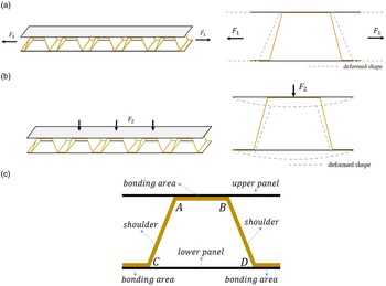
The classic corrugated flexible skin (CCFS) is composed of corrugated core and two elastic panels [Reference Kazemahvazi and Zenkert28], as shown in Fig. 1. In order to achieve large deformation in the corrugation direction, the panels are always made of super-elastic material, such as silicone rubber. The mechanical behaviors of the CCFS in different directions are as follows: (1) In the corrugation direction, when the tensile load
 ${F_1}$
is applied to the flexible skin (Fig. 1(a)), the upper and lower panels made of silicone rubber undergo large tensile deformation. At the same time, its bonding areas of corrugated core (Fig. 1(c)) are subjected to shearing force in the corrugation direction. Under this shearing force, the shoulders of corrugation core undergo bending deformation (Fig. 1(a)). Thus, the CCFS has the capability to produce large deformation in the corrugation direction. (2) In the direction perpendicular to corrugation, when distributed load
 ${F_2}$
, such as aerodynamic load, is applied to the upper panel (Fig. 1(b)), there are bending moments distributed along the corrugation direction in the whole structure, consequently, the deflection of the flexible skin along the corrugation direction occurs, which is detrimental to aerodynamic performance.
The classic corrugated flexible skin (CCFS): (a) Tensile case; (b) Bending case; (c) Configuration.

When this corrugated flexible skin is used for morphing aircraft, flexibility along corrugation direction is required to produce continuous smooth deformation, materials with low modulus are usually selected and the thickness of the panels and corrugated core is reduced. These features result in a reduction in bending stiffness, it means that the CCFS has insufficient capability to support aerodynamic loads.
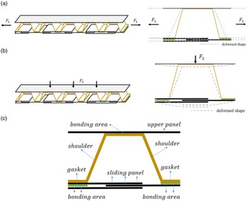
To enhance the bending stiffness, we replace the lower panel of the CCFS with multi-layer sliding panels made of high elastic modulus material such as metal, then bond them to the convex surface of the corrugated core, finally, the corrugated flexible skin with high bending stiffness is obtained. In this paper, we name it the improved corrugated flexible skin (ICFS) for short. As shown in Fig. 2, the ICFS is comprised of upper skin, corrugated core, multi-layer sliding panels and gaskets. The mechanical behaviors of the ICFS in different directions are discussed as follows: (1) In the corrugation direction, when the tensile load
 ${F_1}$
is applied to the flexible skin (Fig. 2 (a)), upper panel and corrugated core of the ICFS have the same deformation form as that of the CCFS. However, the multi-layer sliding panels are stretched by sliding. This results in a certain reduction in the tensile stiffness of the ICFS. (2) In the direction perpendicular to corrugation, when distributed load
 ${F_2}$
(such as aerodynamic load) is applied to the upper panel (Fig. 2(b)), the bending moments distributed along the corrugation direction in the whole structure have produced. In this case, the sliding panels made of high modulus material squeeze each other, the bending deformation of the ICFS can be limited effectively. Thus, the ICFS is a capable of offering a higher bending stiffness than the CCFS, and has larger aerodynamic load bearing capacity.
The improved corrugated flexible skin (ICFS): (a) Tensile case; (b) Bending case; (c) Configuration.

2.2 Analytical model
In this section, the analytical solutions are presented for calculating the equivalent tensile and bending properties of the classic and improved corrugated flexible skin. During the improvement of the corrugated flexible skin, only the lower skin was replaced, and the upper skin remained unchanged. Therefore, to simplify the analytical model used to compare the stiffness change before and after the improvement, we mainly considered the effect of the lower panel, while the upper panel will be considered in the numerical simulation. A unit cell of corrugated flexible skin is considered without the upper panel, and the shear force in the structure is ignored. Two necessary assumptions should be proposed for further simplifying the calculation process as follows: (1) For the classic flexible corrugated skin, since the ratio of the lower panel Young’s modulus to the corrugated core Young’s modulus is very small, the lower panel in the areas overlapped with the corrugated core can be ignored. (2) For the improved flexible corrugated skin, it is assumed that the sliding panels are in smooth contact with each other and cannot provide any tensile stiffness under tensile or bending conditions. In addition, in order to avoid dealing with the indeterminate loading configuration of the structure, the equilibrium and compatibility equations should be required to find the force distribution in the elastomeric members.
Geometric parameters of classic corrugated flexible skin under tensile condition are shown in Fig. 3(a), our objective is to calculate the tensile displacement which can be applied for evaluating the equivalent elastic modulus of this structure. To avoid dealing with the indeterminate loading configuration, the structure is divided into two parts including corrugated core and lower panel (Fig. 3(b)), and the compatibility equation that tensile displacement of part CABD of the corrugated core is equal to that of the lower panel is obtained. Then the force f can be calculated by this compatibility equation. At this point, the total tensile displacement of the structure is equal to the sum of the tensile displacement of part OC and DE of corrugated core and the lower panel. The specific calculation process is as follows.
A unit cell of the CCFS without upper panel under tensile condition.

The tensile displacement of part CABD of the corrugated core is obtained using Castiglione’s second theorem, and the virtual force g must be applied at node D. The strain energy of each member due to the bending moment and axial force may be calculated as:
 \begin{align}\left\{ {\begin{array}{*{20}{c}}{U_{AB}^t = \dfrac{{{{\left( {F + g - f} \right)}^2}{a_3}}}{{{E_1}{A_1}}},\;\;\;\;\;\;\;\;\;\;\;\;\;\;\;\;\;\;\;\;\;\;\;U_{AB}^b = \dfrac{{{a_3}{h^2}{{\left( {F + g - f} \right)}^2}}}{{{E_1}{I_1}}}\;\;\;\;\;\;\;\;\;\;\;\;\;}\\ \\[-5pt]{U_{AC}^t = U_{BD}^t = \dfrac{{{{\left( {F + g - f} \right)}^2}s{a_2}}}{{2{E_1}{A_1}}},\;\;\;\;\;\;\;\;U_{AC}^b = U_{BD}^b = \dfrac{{a_2^3{c^2}{{\left( {F + g - f} \right)}^2}}}{{6{E_1}{I_1}{s^3}}}}\end{array}} \right.\end{align}
Here
 ${E_1}$
,
 ${A_1}$
and
 ${I_1}$
represent Young’s modulus’ cross-sectional area and second moment of cross-sectional area of the corrugated core respectively. Moreover s and c denote
 $sin\alpha $
and
 $cos\alpha $
respectively. The total strain energy of part CABD can be expressed as:
 \begin{align}{U_{CABD}} = U_{BD}^t + U_{AC}^t + U_{AB}^t + U_{BD}^b + U_{AC}^b + U_{AB}^b\end{align}
Differentiating this strain energy respect to virtual force g, the displacement can be obtained:
 \begin{align}{\delta _{CABD}} = {\left. {\frac{{\partial {U_{CABD}}}}{{\partial g}}} \right|_{g = 0}} = \frac{{2{a_3}\!\left( {F - f} \right)\!}}{{{E_1}{A_1}}} + \frac{{2\!\left( {F - f} \right)\!{a_2}{h^2}}}{{3{E_1}{I_1}s}} + \frac{{2\!\left( {F - f} \right)\!{a_3}{h^2}}}{{{E_1}{I_1}}} + \frac{{2\!\left( {F - f} \right)\!s{a_2}}}{{{E_1}{A_1}}}\end{align}
The elongation of the lower panel is:
 \begin{align}{\delta _{panel}} = \frac{{2f\!\left( {{a_2} + {a_3}} \right)}}{{{E_2}{A_2}}}\end{align}
Where
 ${E_2}$
and
 ${A_2}$
represent Young’s modulus and cross-sectional area of the lower panel respectively. According to the compatibility equation
 ${\delta _{CABD}} = {\delta _{panel}}$
, the force f can be calculated as:
 \begin{align}\left\{ {\begin{array}{*{20}{c}}{f = \mu F}\\ \\[-6pt] {\mu = \dfrac{{{E_2}{A_2}\!\left( {{A_1}{a_2}{h^2} + 3{a_2}{I_1}{s^2} + 3{A_1}{a_3}{h^2}s + 3{a_3}{I_1}s} \right)}}{{{A_1}{a_2}{A_2}{E_2}{h^2} + 3{A_1}{A_2}{a_3}{E_2}{h^2}s + 3{A_1}{a_2}{E_1}{I_1}s + 3{A_1}{a_3}{E_1}{I_1}s + 3{A_2}{a_3}{E_2}{I_1}s + 3{a_2}{A_2}{E_2}{I_1}{s^2}}}}\end{array}} \right.\end{align}
By replacing f with above expression, the elongation of the lower panel
 ${\delta _{panel}}$
can be obtained as:
 \begin{align}{\delta _{panel}} = \frac{{2\mu F\!\left( {{a_2} + {a_3}} \right)}}{{{E_2}{A_2}}}\end{align}
Therefore, the total tensile displacement of the structure can be calculated by adding the tensile displacement of the lower panel and the part
 $OC,DE$
of the corrugated core as:
 \begin{align}\delta = \frac{{2\mu F\!\left( {{a_2} + {a_3}} \right)}}{{{E_2}{A_2}}} + \frac{{2F{a_3}}}{{{E_1}{A_1}}}\end{align}
And the equivalent tensile modulus of a unit cell of the CCFS is:
 \begin{align}E_{CCFS}^t = \frac{{Fl}}{{wh\delta }} = \frac{{{E_1}{A_1}{E_2}{A_2}\!\left( {a1 + a2 + a3} \right)}}{{wh\!\left( {\mu {E_1}{A_1}{a_2} + \mu {E_1}{A_1}{a_3} + {E_2}{A_2}{a_3}} \right)}}\end{align}
Where l, w represent length and width of a corrugated unit cell respectively.
Geometric parameters of improved corrugated flexible skin under tensile condition are shown in Fig. 4(a). Since sliding panels do not provide tensile stiffness, the structure can be simplified as shown in Fig. 4(b). According to Castiglione’s second theorem, the tensile displacement of the structure is calculated by differentiating total strain energy with respect to force F. The strain energy of each component is calculated as:
 \begin{align}\left\{ {\begin{array}{*{20}{c}}{U_{AB}^t = \dfrac{{{F^2}{a_3}}}{{{E_1}{A_1}}},\;\;\;\;\;\;\;\;\;\;\;\;\;\;\;\;\;\;\;\;\;\;\;U_{AB}^b = \dfrac{{{a_3}{h^2}{F^2}}}{{{E_1}{I_1}}}\;}\\ \\[-6pt]{U_{AC}^t = U_{BD}^t = \dfrac{{{F^2}s{a_2}}}{{2{E_1}{A_1}}},\;\;\;\;\;\;\;\;U_{AC}^b = U_{BD}^b = \dfrac{{a_2^3{c^2}{F^2}}}{{6{E_1}{I_1}{s^3}}}}\end{array}} \right.\end{align}
A unit cell of the ICFS without upper panel under tensile condition.

Adding these terms together, and total strain energy of the structure can be expressed as:
 \begin{align}U = U_{BD}^t + U_{AC}^t + U_{AB}^t + U_{OC}^t + U_{DE}^t + U_{BD}^b + U_{AC}^b + U_{AB}^b\end{align}
Therefore, the tensile displacement of the structure is:
 \begin{align}\delta = \frac{{\partial U}}{\partial F} = \frac{{2F\!\left( {{a_1} + {a_3}} \right)}}{{{E_1}{A_1}}} + \frac{{2F{a_2}{h^2}}}{{3{E_1}{I_1}s}} + \frac{{2F{a_3}{h^2}}}{{{E_1}{I_1}}} + \frac{{2Fs{a_2}}}{{{E_1}{A_1}}}\end{align}
And the equivalent tensile modulus of a unit cell of the ICFS is:
 \begin{align}E_{ICFS}^t = \frac{{Fl}}{{wh\delta }} = \frac{{3{E_1}{A_1}{I_1}{s^3}\left( {a1 + a2 + a3} \right)}}{{wh\!\left( {{A_1}a_2^3{c^2} + 3{A_1}{a_3}{h^2}{s^3} + 3{a_2}{I_1}{s^3} + 3{a_3}{I_1}{s^3} + 3{a_2}{I_1}{s^4}} \right)}}\end{align}
Geometric parameters of the classic corrugated flexible skin under bending condition are shown in Fig. 5(a). In order to avoid dealing with the indeterminate loading configuration, the structure is also divided into two parts including corrugated core and the lower panel (Fig. 5(b)), and force f could be calculated by compatibility equation that tensile displacement of part CABD of the corrugated core is equal to that of the lower panel. Then the rotation angle generated by the external moment M and force f of the corrugated core is the rotation angle of the structure. The specific calculation process is as follows.
A unit cell of the CCFS without upper panel under bending condition.

According to Castiglione’s second theorem, the virtual force g must be applied at node D and the strain energy of each component is calculated as:
 \begin{align}\left\{ {\begin{array}{*{20}{l}}{U_{AB}^t\ \ = \dfrac{{{{\left( {g - f} \right)}^2}{a_3}}}{{{E_1}{A_1}}},}\ \ {U_{AB}^b = \dfrac{{{{\left( {M + gh - fh} \right)}^2}{a_3}}}{{{E_1}{I_1}}}}\\ \\[-5pt]{U_{AC}^t = U_{BD}^t = \dfrac{{{{\left( {g - f} \right)}^2}{a_2}s}}{{2{E_1}{A_1}}},}\ \ {U_{AC}^b = U_{BD}^b = \dfrac{{{a_2}\!\left( {a_2^2{c^2}{{\left( {g - f} \right)}^2} + 3{a_2}cMs\!\left( {g - f} \right) + 3{M^2}{s^2}} \right)}}{{6{E_1}{I_1}{s^3}}}}\\ \\[-5pt]{U_{OC}^b = \dfrac{{{M^2}{a_1}}}{{{E_1}{I_1}}},}\ \ {U_{DE}^b = \dfrac{{{M^2}{a_1}}}{{{E_1}{I_1}}}}\end{array}} \right.\end{align}
The total strain energy of part CABD of the corrugated core can be expressed as:
 \begin{align}{U_{CABD}} = U_{BD}^t + U_{AC}^t + U_{AB}^t + U_{BD}^b + U_{AC}^b + U_{AB}^b\end{align}
Tensile displacement of part CABD could be obtained by differentiating total strain energy respect to force g.
 \begin{align}{\delta _{CABD}} = {\left. {\frac{{\partial {U_{CABD}}}}{{\partial g}}} \right|_{g = 0}} = - \frac{{2{a_3}f}}{{{E_1}{A_1}}} + \frac{{2{a_3}h\!\left( {M - fh} \right)}}{{{E_1}{I_1}}} - \frac{{2{a_2}fs}}{{{E_1}{A_1}}} + \frac{{{a_2}(\!-\!2a_2^2{c^2}f + 3{a_2}cMs)}}{{3{E_1}{I_1}{s^2}}}\end{align}
The elongation of the lower panel is:
 \begin{align}{\delta _{panel}} = \frac{{2f\!\left( {{a_2} + {a_3}} \right)}}{{{E_2}{A_2}}}\end{align}
The force f could be calculated by compatibility equation
 ${\delta _{CABD}} = {\delta _{panel}}$
.
 \begin{align}\left\{ {\begin{array}{*{20}{l}}{f = \mu M}\\ \\[-7pt] {\mu = \dfrac{{3{A_1}{A_2}{E_2}s\left( {a_2^2c + 2{a_3}h{s^2}} \right)}}{{2\left( {{A_1}a_2^3{A_2}{c^2}{E_2} + 3{A_1}{A_2}{a_3}{E_2}{h^2}{s^3} + 3{A_1}{a_2}{E_1}{I_1}{s^3} + 3{A_1}{a_3}{E_1}{I_1}{s^3} + 3{A_2}{a_3}{E_2}{I_1}{s^3} + 3{a_2}{A_2}{E_2}{I_1}{s^4}} \right)}}}\end{array}} \right.\end{align}
The total strain energy of the corrugated core is:
 \begin{align}{U_{OCABDE}} = U_{BD}^t + U_{AC}^t + U_{AB}^t + U_{OC}^b + U_{AC}^b + U_{AB}^b + U_{BD}^b + U_{DE}^b\end{align}
Therefore, the rotation angle of the structure is:
 \begin{align}\theta &= \frac{{\partial {U_{OCABDE}}}}{{\partial M}} = \frac{{2M{a_1} + 2{\mu ^2}M{a_3} + 2{\mu ^2}M{a_2}s}}{{{E_1}{I_1}}} + \frac{{2{a_3}\!\left( {1 - \mu h} \right)\left( {M - \mu hM} \right)}}{{{E_1}{I_1}}}\nonumber\\[3pt] &\quad + \frac{{2{a_2}M\!\left( {3{s^2} - 3\mu {a_2}cs + {\mu ^2}a_2^2{c^2}} \right)}}{{3{E_1}{I_1}{s^3}}}\end{align}
And the equivalent bending modulus of a unit cell of the CCFS is:
 \begin{align}&E_{CCFS}^b = {{Ml} \over {w{h^3}\theta }} = {1 \over {w{h^3}}}. \nonumber\\[3pt]&\frac{{3{E_1}{A_1}{I_1}{s^3}\left( {a1 + a2 + a3} \right)}}{{3{A_1}{a_2}{s^2} + 3{a_1}{A_1}{s^3} + 3{a_3}{A_1}{s^3} - 3\mu {A_1}a_2^2cs - 6\mu {A_1}{a_3}h{s^3} + \mu {A_1}a_2^3{c^2} + 3{\mu ^2}{A_1}{a_3}{h^2}{s^3} + 3{\mu ^2}{a_3}{I_1}{s^3} + 3{\mu ^2}{a_2}{I_1}{s^4}}}\;\end{align}
Geometric parameters of the improved corrugated flexible skin under bending condition are shown in Fig. 6(a). To deal with this the indeterminate loading configuration, it is necessary to cut off the structure from point D, and there are interaction forces
 ${X_1}$
,
 ${X_2}$
and
 ${X_3}$
between the corrugated core and the sliding panels at this point (Fig. 6(b)). Since smooth contact between sliding panels does not provide any tensile stiffness is assumed, the force
 ${X_1} = 0$
. The forces
 ${X_2}$
and
 ${X_3}$
can be calculated by the compatibility conditions that the deformation of corrugated core and sliding panel is consistent at point D. At this point, the rotation angle generated by the external moment M and the forces
 ${X_2}$
and
 ${X_3}$
on the corrugated core is the rotation angle of the structure.
A unit cell of the ICFS without upper panel under bending condition.

The compatibility equations can be understood as the sum of the tensile displacement of the part CABD and sliding panel in the
 ${X_2}$
or
 ${X_3}$
direction is zero. Strain energy of corresponding components are calculated as:
 \begin{align}\left\{ {\begin{array}{*{20}{l}}{U_{BD}^t = \dfrac{{X_2^2{c^2}{a_2}}}{{2{E_1}{A_1}s}},}\quad {U_{BD}^b = \dfrac{{{a_2}\!\left( {3{M^2} + a_2^2X_2^2 + 3{a_2}{X_2}{X_3} + 3X_3^2 - 3M\left( {{a_2}{X_2} + 2{X_3}} \right)} \right)}}{{6{E_1}{I_1}s}}}\\ \\[-6pt]{U_{AB}^t = 0,}\qquad\qquad\!\!\kern0.5pt {U_{AB}^b = \dfrac{{{{\left( {M - {a_2}{X_2} - {X_3}} \right)}^3} + {{\left( { - M + {a_2}{X_2} + 2{a_3}{X_2} + {X_3}} \right)}^3}}}{{6{E_1}{I_1}{X_2}}}}\\ \\[-6pt]{U_{AC}^t = \dfrac{{X_2^2{c^2}{a_2}}}{{2{E_1}{A_1}s}},} \kern0.5pt\quad {U_{AC}^b = \dfrac{{{{\left( {M - {a_2}{X_2} - 2{a_3}{X_2} - {X_3}} \right)}^3} + {{\left( { - M + 2{a_2}{X_2} + 2{a_3}{X_2} + {X_3}} \right)}^3}}}{{6{E_1}{I_1}s{X_2}}}}\\ \\[-6pt]{U_{panel}^t = 0,}\qquad\quad {U_{panel}^b = \dfrac{{ - X_3^3 + {{\left( {2\left( {{a_2} + {a_3}} \right){X_2} + {X_3}} \right)}^3}}}{{6{E_4}{I_4}{X_2}}}}\end{array}} \right.\end{align}
Where
 ${E_4}$
and
 ${I_4}$
represent the equivalent bending modulus and equivalent second moment of cross-sectional area of sliding panel CD respectively, its detail derivation is shown in Appendix. The sum of strain energy of part CABD and sliding panel CD is:
 \begin{align}{U_{CABD,CD}} = U_{BD}^t + U_{AB}^t + U_{AC}^t + U_{panel}^t + U_{BD}^b + U_{AB}^b + U_{AC}^b + U_{panel}^b\end{align}
Through the compatibility equations
 ${\theta _1} = \frac{{\partial U}}{{\partial {X_2}}} = 0$
and
 ${\theta _2} = \frac{{\partial U}}{{\partial {X_3}}} = 0$
, the forces
 ${X_2}$
and
 ${X_3}$
can be calculated as:
 \begin{align}\left\{ {\begin{array}{*{20}{l}}{{X_2} = 0\;\;\;\;\;\;\;\;\;\;\;\;\;\;\;\;\;\;\;\;\;\;\;\;\;\;\;\;\;\;\;\;\;\;\;\;\;\;\;\;\;\;\;\;\;\;\;\;\;\;\;\;\;\;\;\;\;\;\;}\\ \\[-6pt]{{X_3} = \mu M = \dfrac{{{E_4}{I_4}M\left( {{a_2} + {a_3}s} \right)}}{{{a_2}{E_4}{I_4} + {a_2}{E_1}{I_1}s + {a_3}{E_1}{I_1}s + {a_3}{E_4}{I_4}s}}}\end{array}} \right.\end{align}
The strain energy of each component of the corrugated core is:
 \begin{align}\left\{ {\begin{array}{*{20}{l}}{U_{DE}^b = U_{OC}^b = \dfrac{{{M^2}{a_1}}}{{2{E_3}{I_3}}}\;\;\;\;\;\;\;\;\;\;\;}\\ \\[-6pt]{U_{BD}^b = \;U_{AC}^b = \dfrac{{{{\left( {M - \mu M} \right)}^2}{a_2}}}{{2{E_1}{I_1}s}}\;}\\ \\[-6pt]{U_{AB}^b = \dfrac{{{{\left( {M - \mu M} \right)}^2}{a_3}}}{{2{E_1}{I_1}}}\;\;\;\;\;\;\;\;\;\;\;\;\;\;\;}\end{array}} \right.\end{align}
Where
 ${E_3}$
and
 ${I_3}$
represent Young’s modulus and second moment of cross-sectional area of the part OC and DE. The total strain energy of the corrugated core is:
 \begin{align}{U_{OCABDE}} = U_{BD}^b + U_{AB}^b + U_{AC}^b + U_{DE}^b + U_{OC}^b\end{align}
Therefore, the rotation angle of the structure is:
 \begin{align}\theta = \frac{{\partial {U_{OCABDE}}}}{{\partial M}} = \frac{{2M\left( {{a_2}{E_3}{I_3} + {a_1}{E_1}{I_1}s + {a_3}{E_3}{I_3}s - 2\mu {a_2}{E_3}{I_3} - 2\mu {a_3}{E_3}{I_3}s + {\mu ^2}{a_2}{E_3}{I_3} + {\mu ^2}{a_3}{E_3}{I_3}s} \right)}}{{{E_1}{E_3}{I_1}{I_3}s}}\end{align}
And the equivalent bending modulus is:
 \begin{align}E_{ICFS}^b = \frac{{Ml}}{{w{h^3}\theta }} = \frac{{{E_1}{E_3}{I_1}{I_3}s\left( {a1 + a2 + a3} \right)}}{{w{h^3}\left( {{a_2}{E_3}{I_3} + {a_1}{E_1}{I_1}s + {a_3}{E_3}{I_3}s - 2\mu {a_2}{E_3}{I_3} - 2\mu {a_3}{E_3}{I_3}s + {\mu ^2}{a_2}{E_3}{I_3} + {\mu ^2}{a_3}{E_3}{I_3}s} \right)}}\end{align}
After the equivalent tensile and bending modulus are obtained, it is necessary to verify the advantage of the improved corrugated flexible skin by comparing the two kinds of skins. For this purpose, the parameter values are given in Table 1. Among them,
 ${E_3}$
represents Young’s modulus of the combination of metal panel and the corrugated core, and its value is assumed as average of
 ${E_{metal}}$
and
 ${E_1}$
. According to these parameter values, the equivalent tensile and bending modulus of two kinds of skins can be calculated, and the results are shown in Table 2. The ratio of
 $E_{CCFS}^{t}$
to
 $E_{ICFS}^{t}$
is 1.04 reveals that the equivalent tensile modulus of the ICFS is slightly smaller than that of the CCFS. And the ratio of
 $E_{CCFS}^b$
to
 $E_{ICFS}^b$
is 0.39 means that the equivalent bending modulus of the ICFS is larger than double that of the CCFS. Therefore, the stiffness of the corrugated flexible skin to support bending load has been enhanced, while the flexibility is remained in the tensile direction.
Parameter values for equivalent modulus calculation

Results of equivalent modulus and ratios

2.3 Numerical simulation
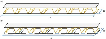
In order to verify the effectiveness of the method to improve bending stiffness of the flexible skin, two designs of the CCFS and the ICFS are provided in this section, then the corresponding numerical simulations are completed by Abaqus. The two types of flexible skin have the same total length
 $L = 399.0mm$
and width
 $W = 60.0mm$
, the corrugated cores of them are consisted of seven unit cells, as shown in Fig. 7. The specific geometric parameters of unit cell are shown in Fig. 8 and Table 3. The corrugated cores are made of flexible material, elastic modulus is
 $E = 9,000.0MPa$
(Reference Rudenko, Hannig, Monner and Horst29). The elastic panels are made of silicone rubber,
 $E = 4.5MPa$
, and the multi-layer sliding panels are made of Aluminum,
 $\;E = 72,000.0MPa$
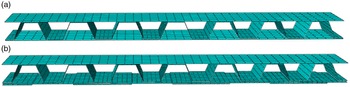
. All structure is modelled by shell elements, SR4. Tie connections are used to simulate glue bonding in corrugated flexible skin. For the ICFS, surface-to-surface contact is defined between sliding panels. The finite element models are shown in Fig. 9.
Geometric parameter values of unit cell

(a) The CCFS with seven unit cells; (b) The ICFS with seven unit cells.

Geometric parameters of unit cell: (a) The CCFS; (b) The ICFS.

Finite element model of two flexible skin: (a) The CCFS; (b) The ICFS.

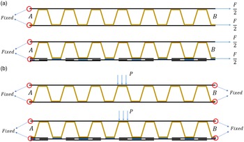
In this paper two load cases are studied to discuss abilities of stretching and supporting aerodynamic load, as shown in Fig. 10. In tensile case, the left end (A) of the structure is fixed and a force (F=2.000N) along the corrugation direction is applied on the right end(B). In bending case, both left and right ends of the structure is fixed and a uniform pressure of
 $P = 0.005{\textrm{MPa}}$
is applied in the bonding area between the upper skin and the middle unit cell of the corrugated core. The loads in tensile and bending cases are determined by the following two principles: (1) The out-of-plane displacements due to air pressure loading should be kept below 1 mm [Reference Schorsch, Nagel and Lühring30], otherwise deflection on the upper surface of the flexible skin would cause detrimental effects on aerodynamic performance [Reference Airoldi, Fournier, Borlandelli, Bettini and Sala3]. (2) The maximum strain along the length direction of rubber should be kept below 10%, otherwise it would fail due to fatigue after several loading cycles [Reference Schorsch, Nagel and Lühring30]. The numerical simulation of the two kinds of flexible skins is conducted under tensile and bending cases, as shown in Table 4.
Load cases: (a) Tensile; (b) Bending.

Load cases and results of simulation

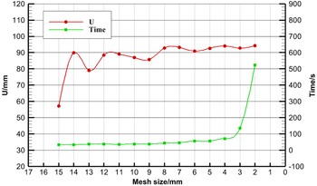
We have performed mesh convergence and computational efficiency of the finite element model by taking the improved corrugated flexible skin (ICFS) under tensile condition as an example through Abaqus software. Since the whole flexible skin is simulated by shell element, the minimum mesh size should be larger than thickness of the shell element in this study. The maximum tensile deformation (U) of the ICFS as mesh size reduced from 15 to 2mm and computation time of its finite element model is shown in Table 5 and Fig. 11. The result reveals that the tensile deformation values tend to be between 90 and 95mm as the decrease of mesh size, and its computation time increases exponentially when the mesh size is less than 3mm. Therefore, in order to obtain good time-solving and results accuracy, we have chosen 3mm as mesh size during numerical simulations of two kinds of flexible skin.
The maximum tensile deformation(U) of the ICFS and its computation time as mesh size reduced from 15 to 2mm

Meshing convergence and computational efficiency study of ICFS.

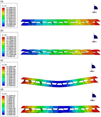
The static liner analysis is conducted by Abaqus to calculate the deformations of structure. Results are shown in Fig. 12. For the tensile condition, the maximum deformation of the ICFS is 92.800mm, which is about 1.3 times that of the CCFS (72.480mm). It means that the ICFS has smaller tensile stiffness than the CCFS. The reason is that the tensile stiffness of the lower panel is sharply reduced by replacing the lower elastic panel made of silicone rubber with multi-layer sliding metal panels. For the bending condition, the maximum deformation of the ICFS is 1.565mm, which is about 1/21 of the maximum deformation of the CCFS (21.760mm). It means that the ICFS has a higher capability to resist bending load than the CCFS. The reason is that the sliding panels can improve the bending stiffness of the flexible skin by grinding against each other. Therefore, the ICFS can obtain a high bending stiffness.
The deformation of flexible skin: (a) Tensile deformation of the CCFS; (b) Tensile deformation of the ICFS; (c) Bending deformation of the CCFS; (d) Bending deformation of the ICFS.

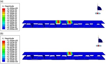
In addition, during the bending case the upper panel of the corrugated flexible skin is compressed and the buckling has to be evaluated. Similarly, the linear buckling analysis for two types of flexible skins is performed by the finite element software Abaqus and the relevant geometric and property parameters are consistent with the finite element model for static analysis. The results are shown in Fig. 13, through the numerical simulation analysis, the critical buckling pressure of the CCFS is
 $3.63 \times {10^{ - 4}}$
MPa, and that of the ICFS is
 $2.49 \times {10^{ - 3}}$
MPa.
The linear buckling analysis of flexible skin in bending case: (a) The Buckling analysis of the CCFS; (b) The buckling analysis of the ICFS.

2.4 Experiment
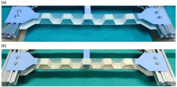
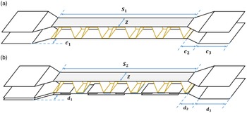
In this section, the specimens of two flexible skins (the CCFS and ICFS, as shown in Fig. 14) are designed and manufactured by 3D printing technology to examine the capacities of stretching in the corrugation direction and resisting load in the direction perpendicular to corrugation. Due to limit of capability of 3D printer, the corrugated cores of two specimens are consisted of five unit cells. The geometric parameters of corrugated unit cell are shown in Fig. 8 and Table 3, other geometric parameters are shown in Fig. 15 and Table 6. The corrugated core is printed by photosensitive resin (UTR8220), the elastic panels is made of silicone rubber and the sliding panels is made of Aluminum.
The specimens of two flexible skins: (a) The CCFS; (b) The ICFS.

The specimen concept of two flexible skins: (a) The CCFS; (b) The ICFS.

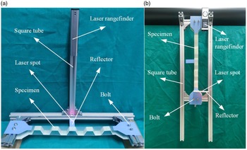
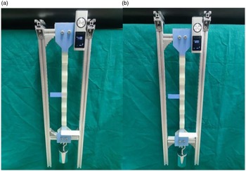
An experiment platform is set up, as shown in Fig. 16, the main frame consists of square tubes. A laser rangefinder is glued to the square tubes with 3M glue and used to measure the deformation. The specimen is fixed on the square tubes by bolts. For the bending case, the load is simulated by a weight located on the upper panel of the specimen, deformations of the specimen center point are measured by laser rangefinder. For the tensile case, the laser rangefinder is glued on the fixed end of the specimen, and the weight is hung at the free end to simulate tensile load, stretching deformations are also measured by the laser rangefinder. It should be noted that gravity will cause deformation of the specimen before experiment, and this initial deformation should be measured and subtracted from the deformation under load.
Platform of experiments: (a) Bending case; (b) Tensile case.

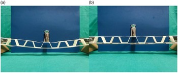
Four experiments are conducted. Experiment 1 and 2 are used to compare the bending deformations between the CCFS and the ICFS. In these two experiments a 100g weight is placed in the middle position of upper panel of the flexible skin to produce the bending moments, as shown in Fig. 17. Experiments 3 and 4 are used to compare the tensile deformations between the CCFS and the ICFS. In these two experiments a 1kg weight is hanging at the free end of the structure, as shown in Fig. 18. Load cases and results in experiments are listed in Table 7.
(a) Experiment 1; (b) Experiment 2.

(a) Experiment 3; (b) Experiment 4.

In experiment 1, deformation of center of the CCFS in length is 10mm, and that of the ICFS is 2mm in experiment 2. It shows that the bending deformation of the ICFS is significantly decreased by 5 times comparing with the that of CCFS. The reason is that the bending deformation of the ICFS is limited effectively by grinding against each other of the metal sliding panels.
In experiment 3 and 4, the tensile deformation of the CCFS is 22mm, and that of ICFS is 29mm. It shows that the larger tensile deformation is obtained by replacing elastic deformation of silicone rubber with sliding motion between metal sliding panels.
Consequently, the ICFS has more tensile flexibility in the corrugation direction, and higher bending stiffness in the direction perpendicular to corrugation. In addition, it is necessary to consider the buckling of the upper panel on two kinds of flexible skins in the bending case. In experiment 1, it can be observed that the buckling deformation occurs at both sides of upper panel on the middle-corrugated unit cell of the CCFS, this phenomenon is consistent with the results of numerical simulation. In experiment 2, the bucking deformation appears on the right side in the middle of the upper panel of the ICFS, and this result is slightly different from the numerical simulation. The reason is geometric parameters, material properties and the number of corrugated unit cells are different between the experiment and the numerical simulation.
Geometric parameters of the specimens

Load cases and results

3.0 Application in aircraft structure
3.1 Application procedure
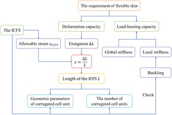
An application procedure of the improved corrugated flexible skin to morphing aircraft structure is proposed here. Through this procedure the geometric parameters of the ICFS can be determined. The flow chart in Fig. 19 gives the process in detail. For morphing aircraft, the requirements of flexible skin include load-bearing capacity and deformation capacity. The load carrying capacity is determined by local stiffness and global stiffness. Local stiffness of flexible skin determines the ability to resist aerodynamic pressure, and has a strong influence on the smoothness of the skin. In particular, the buckling deformation is a typical phenomenon that affects local stiffness of flexible skin, and it is necessary to conduct buckling analysis when the design of ICFS is finished. The bending deformation of flexible skin is determined by global stiffness of flexible skin. According to the flow chart (Fig. 19), the design process of the ICFS can be composed of five steps.
-
(1) According to movement of aircraft morphing structure, the elongation of flexible skin (
$\Delta L$
) can be determined by geometrical analysis. -
(2) According to the allowable strain of material (
${\varepsilon _m}$
) of the upper panel in the ICFS, the allowable strain of the ICFS (
${\varepsilon _{ICFS}}$
) can be determined (
${\varepsilon _{ICFS}} = {\varepsilon _m}$
). -
(3) According to definition of strain (
${\varepsilon _{ICFS}} = \varepsilon = \Delta L/L$
), the length of the ICFS (L) can be calculated. -
(4) After the length of the ICFS (L) is obtained, geometric parameters and the number of corrugated unit cells in the ICFS can be determined based on the conceptual design of the ICFS.
-
(5) Once the ICFS design is completed, a buckling analysis needs to be performed to check its local load carrying capacity.


Flow chart of application procedure.

3.2 Example of drooping leading edge
As a kind of high lift device, drooping leading edge is widely used in aviation. But it has a drawback that there is a gap appearing in the upper skin in order to achieve drooping movement (Fig. 20), it can cause airflow separation. In order to overcome this problem, the ICFS is used to replace a part of the upper skin in the drooping leading edge. And based on the purpose of verifying the stretching ability of the improved corrugated flexible skin (ICFS) and whether it can affect the deflection angle of the drooping leading edge, we have designed the movement functional experiment through 3D technology.
Classic drooping leading edge.

According to the application procedure of the ICFS described above, the elongation of flexible skin,
 $\Delta L$
, is determined by geometrical analysis firstly. As shown in Fig. 21, when the leading edge is deflected downward by angle of 6
 $^\circ $
, end point A of the upper skin moves to point B, so skin elongation of leading edge equals to the length of black curve from point A to point B,
 $\Delta L = 33.5mm$
. In tensile deformation of the ICFS, the allowable strain of the whole structure should be determined based on the part where there is maximum value of the strain in the ICFS, and the allowable strain of the ICFS equals to the limit strain of material of this part. Here, since maximum strain of silicone rubber considering fatigue failure should be kept below
 $10{\textrm{% }}$
[Reference Schorsch, Nagel and Lühring30], the allowable strain of the ICFS is determined by the silicone rubber,
 ${\varepsilon _{ICFS}} = {\varepsilon _{rubber}} = 10{\textrm{% }}$
. According to definition of strain,
 $\varepsilon = \Delta L/L$
, the length of the ICFS can be calculated,
 $L = 335mm$
. Based on the conceptual design of the ICFS, geometric parameters of corrugated unit cell are determined as shown in Fig. 22 and Table 8, the number of corrugated unit cells is
 $N = 5$
.
Measurement of skin elongation.

Geometric parameters of corrugated unit cell.

Geometric parameters of corrugated unit cell

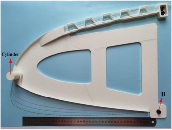
When the design of the ICFS is finished, a full-scale demonstrator of drooping leading edge with the ICFS can be manufactured by 3D printing technology, as shown in Fig. 23. The length of the demonstrator is 457mm, and the height is 331.64mm. The upper panel of the ICFS is made of silicone rubber, and other parts of demonstrator are made of PLA (Raise3D Premium PLA), 3M glue is used to bond silicone rubber and corrugated core. The right end of the ICFS is fixed by two bolts (diameter is 6mm). The lower right corner (point B) of the demonstrator is hinged and the entire leading edge can rotate around it. A cylinder near the leading-edge point is used to apply the force to make the leading edge rotate around point B.
Demonstrator of drooping leading edge with the ICFS.

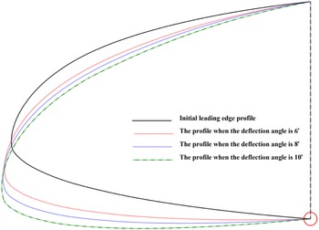
To verify the movement function of the drooping leading edge with the ICFS, a force is applied on the cylinder near the leading-edge point, the leading edge will rotate around point B. Different deflection angles of the leading edge can be obtained by altering the force. The drooping leading edge without the ICFS is deflected downward by angles of
 $6^\circ ,8^\circ ,10^\circ $
and the profiles of them are drawn by different color lines as shown in Fig. 24. These profiles are used as references to study the movement function of the droop leading edge with the ICFS.
Reference profiles when the defection angle is
 $6^\circ ,8^\circ ,10^\circ $
.

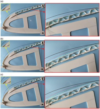
When an appropriate force is applied on the cylinder, the shape of the demonstrator approaches to the reference profile of leading edge (red line, the deflection angle is
 $6^\circ $
), as shown in the left part of Fig. 25(a). It indicates that the drooping leading edge with the ICFS has movement function of deflecting to angle of 6
 $^\circ $
. But there is a certain deviation between the reference profile and the actual shape of the ICFS after deflection, as shown in the right part of Fig. 25(a). In order to further explore the movement ability of the demonstrator, the driving force applied on the cylinder is increased and deflecting downward angle reaches to
 $8^\circ $
,
 $10^\circ $
. Then the shapes of the front of the demonstrator are close to reference profiles of the leading edge (the deflection angles are
 $8^\circ $
(blue line),
 $10^\circ $
(green line)), as shown in the left parts of Fig. 25(b), (c). But the deviations between the reference profile and the actual shape of the ICFS after deflection increase sharply, as shown in the right parts of Fig. 25(b), (c).
Demonstrator with different defection angle: (a)
 $6^\circ $
; (b)
 $8^\circ $
; (c)
 $10^\circ $
.

The results show that the drooping leading edge with the ICFS designed by the application procedure proposed in this paper has capability of movement as the classic drooping leading edge. However, there is the deviation between the reference profile and the actual shape of the ICFS after deflection. This phenomenon is caused by the influence of the position, size and way of the driver on the local deformation of the flexible skin. Therefore, the traditional design method of droop leading edge without consideration of driver effect is no longer applicable, and a new design method based on skin deformation and driver coupling needs further study in the future.
4.0 Conclusion
Aiming at the insufficient load-bearing capacity of the classic corrugated flexible skin (CCFS) in the direction perpendicular to the corrugation, the sliding panels are used to replace its lower elastic panel, as a result, an improved corrugated flexible skin (ICFS) is obtained. More aerodynamic load can be resisted by squeezing each other between the sliding panels, it means that the bending stiffness is significantly enhanced. Then, corresponding analytical solutions to calculate the equivalent tensile and bending properties of the classic corrugated flexible skin and the improved corrugated flexible skin are presented, comparisons between the two kinds of flexible skins are also studied. Moreover, the numerical simulation and experiment are conducted to analysis the deformation capacity in the corrugation direction and the loading capacity in the direction perpendicular to the corrugation. Comparing with the CCFS, it is found that the ICFS has higher bending stiffness to resist more aerodynamic loads, meanwhile, the deformability in the corrugation direction is increased.
An application procedure of the ICFS to morphing aircraft structure is proposed in this paper. According to this procedure, the ICFS is applied to the drooping leading edge to eliminate the gap on the upper skin. The experiment shows that drooping leading edge with the ICFS has the same movement function as that of drooping leading edge without the ICFS. This application procedure can be applied to other parts of the aircraft structure. However, there is a deviation between the reference profile and the actual shape of the ICFS after deflection, the reason for this deviation is local deformation of the ICFS.
For further actual application of the improved corrugated flexible skin (ICFS), it is necessary to conduct more accurate numerical simulations which should take geometric and material nonlinearity into account. When the ICFS is used to replace a certain length of upper skin of the drooping leading edge, real aerodynamic loads should be considered. In order to alleviate the local deformation, distributed drive technology is a promising solution. The corresponding research should be conducted in the future.
Acknowledgments
This work was supported by the Foundation of Key Laboratory (Grant no. 61423010301).
Supplementary material
To view supplementary material for this article, please visit https://doi.org/10.1017/aer.2022.80.
Appendix
The part CD of metal sliding panels in the improved corrugated flexible skin consists of three mental plates, as shown in Fig. A.1, the Young’s modulus and the second moment of cross-sectional area of metal plate we assumed is E and I respectively. The objective is to approximate the response of the part CD using a beam model whose properties are selected to be equivalent to those of the original panel. In order to calculate the equivalent bending modulus, the part CD should be divided into three regions including double layer, triple layer and one layer. The second moment of cross-sectional area of corresponding regions are shown in Table A.1, according to it the rotation angle of the part CD which is sum of the three regions can be calculated. Then equivalent second moment of cross-sectional area and the equivalent bending modulus can be easily obtained. The expression for these three variables is as follows, w represents the width of the structure.
 \begin{align}\theta = {{M\!\left( {729{a_2} + 52{a_3}} \right)} \over {702EI}},\,{I_4} = w{t^3},\,{E_4} = {{Ml} \over {I\theta }} = {{1404EI\!\left( {{a_2} + {a_3}} \right)} \over {w{t^3}\!\left( {729{a_2} + 52{a_3}} \right)}}\;\end{align}
The load condition of the part
 ${\textrm{CD}}$
.

Parameters and rotation angle of different regions in the part
 ${\textrm{CD}}$