1. Introduction
In recent years, industrial robots have been widely used for high-precision applications [Reference Brogårdh1]. Different types of industrial robots are developed to carry out various tasks such as painting, welding, manufacturing, assembling, and so on. The requirements for industrial robot performance are accuracy, speed, and versatility of manipulation. To meet this demand, robot control is a key element for robot manufacturers, and a great deal of development work is carried out to increase the performance of robots, reduce their cost, and introduce new functionalities. In terms of controller design, robustness, tracking accuracy, energy consumption, and computational burden must be considered [Reference Luh, Fisher and Paul2–Reference Silva-Ortigoza, Hernández-Márquez, Roldán-Caballero, Tavera-Mosqueda, Marciano-Melchor, García-Sánchez, Hernández-Guzmán and Silva-Ortigoza9]. However, robot manipulator dynamics are known to be highly nonlinear and coupled, which results in poorer control performance at high speeds [Reference Kuo and Wang10, Reference Freund11]. The complex dynamics are the result of varying inertia and interactions between the different joints, and the nonlinear coupled dynamics of the robot manipulator also increases the energy consumption and computational burden of the controller [Reference Kuo and Wang10]. Various nonlinear control strategies have been developed to resolve this problem, such as feedback linearization [Reference Poignet and Gautier12].
Feedback linearization is a tool widely used for controlling nonlinear systems and operates by canceling the nonlinearities in robot dynamics [Reference Wang and Vidyasagar13, Reference Lewis, Abdallah and Dawson14]. With this method, the closed-loop system becomes nominally linear and classical linear system control techniques can then be applied in the controller design, with relative efficiency. However, feedback linearization requires an accurate model and high sampling rate for successful implementation [Reference Spong and Vidyasagar15]. In addition, the computational burden caused by nonlinear and coupled terms cannot be avoided with complex robot structures in feedback control [Reference Slotine16, Reference Tarn, Bejczy, Isidori and Chen17].
For example, computed torque (CT) control is a well-known control law that consists of a propotional derivative (PD) term and the feedback dynamic compensation term calculated from the actual velocity and desired acceleration signals [Reference Shang and Cong18]. CT control offers a wide range of advantages, such as high tracking accuracy, low energy consumption, and more compliant control. However, its major drawback is the precise analytical dynamic models required for torque generation, which cannot always be obtained due to modeling errors and unknown disturbances [Reference Nguyen-Tuong, Seeger and Peters19]. Inaccurate models will lead to low tracking performance in practice, and a complex robot structure also requires an enormous calculations in the CT controller.
The nonlinear model can be said to increase the difficulty in designing suitable controllers for robot manipulators. Some researchers suggest canceling the nonlinearities by removing the complex inertia terms in dynamic models, as these are negligible at low speeds [Reference Sage, De Mathelin and Ostertag20, Reference Barjuei, Boscariol, Gasparetto, Giovagnoni and Vidoni21]. However, at high motion speeds, the errors in the model resulting from this approach become significant and would probably reduce stability, leading to loss of effectiveness in tracking performance.
As described above, it is challenging to find a simple and effective strategy for controlling robot manipulators due to the presence of model nonlinearities and errors. To resolve this problem, a mechatronic design methodology known as Design For Control (DFC) was proposed by ref. [Reference Zhang, Li and Guo22]. The method points out that the performance of the mechatronic system relies not only on the design of the controller but also on the design of its mechanical structure. Controller design is usually considered subsequent to mechanical design, but an appropriate mechanical structure design will lead to a simple dynamic model which makes design of the controller easier. In this paper, an effective design approach is proposed to improve the control performance of two spatial manipulators, based on development of the mechanical structure design. With dynamic decoupling, a simplified system is obtained and effective straightforward control techniques, rather than complex nonlinear control techniques, are applied. There are three ways to create dynamically decoupled manipulators through mechanical transformation: (i) via mass redistribution; (ii) via actuator relocation; and (iii) via the addition of auxiliary links.
To eliminate the coupling and nonlinear torques via mass redistribution, the inertia matrix must be diagonalized and made invariant for all arm configurations [Reference Arakelian, Geng and Lu23–Reference Youcef-Toumi and Asada26]. The linearization and dynamic decoupling of 2-DOF manipulators via mass redistribution has been considered previously [Reference Youcef-Toumi and Asada26]. In this study, all arm constructions yielding decoupled inertia matrices were identified. The proposed approach was applied to serial manipulators in which the axes of joints were not parallel; with parallel axes this approach allows linearization of the dynamic equations but not their dynamic decoupling [Reference Gompertz and Yang27] and cannot therefore be used with planar serial manipulators. As a result, the inertia matrix cannot be decoupled unless the joint axes are orthogonal to each other in serial manipulator arms with an open kinematic chain structure.
As regards the decoupling of dynamic equations via actuator relocation, a review [Reference Arakelian and Xu24] has shown that the remote actuation design concept is not optimal from the point of view of precise reproduction of the end-effector tasks, because it accumulates all errors due to intermediate transmissions. It is evidently much better to connect actuators directly to the links than to use transmission mechanisms. The clearance, flexibility, manufacturing, and assembly errors of the added transmission mechanisms have a negative impact on the robot’s precision. However, to achieve the gravity balancing, the actuator relocation technique is required for the spatial serial manipulators with high degrees of freedom.
The linearization of dynamic equations and their decoupling by adding auxiliary links to redesign the manipulator has also been developed [Reference Coelho, Yong and Alves28–Reference Arakelian, Xu and Baron30]: dynamic decoupling of the manipulator by connecting a two-link group to the initial structure, forming a Scott–Russell mechanism, was proposed by ref. [Reference Xu, Arakelian and Baron31]. Noted that dynamic decoupling via redesign of the manipulator by adding auxiliary links is a promising new approach in robotics. The main contribution of this paper is to propose a mechatronic design combining dynamic decoupling and controllers with simple structures, which results in improvement of controller performance.
As discussed above, taking into account the structural features of the 2R spatial serial manipulator, that is, orthogonality of the joint axes, it can be confidently asserted that dynamic decoupling via mass redistribution is the most expedient approach. Then, with the application of mass redistribution, the controller design is highly facilitated for the decoupled dynamic system. For the 3R spatial serial manipulator, the dynamic decoupling is achieved by combining techniques of mass redistribution and actuator relocation. This paper is organized as follows: Section 2 contains a review of the dynamic decoupling conditions of the spatial serial manipulators and the generation of motion by “bang-bang” profile, enabling reduction of the maximal input torque values. In Section 3, different conventional linear controllers are used to stabilize the decoupled system and track the desired trajectory. Numerical simulations are also carried out. In Section 4, nonlinear controls with simple structures are adopted to stabilize the decoupled dynamic system asymptotically in the presence of parameter uncertainty and external disturbances. Section 5 presents conclusions and perspectives.
2. Decoupled dynamics of the spatial serial manipulators and their motion generation via bang-bang profile
Before addressing the problem of control performance improvement, the dynamic decoupling is considered being implemented in the spatial serial manipulators with revolute joints. According to Lagrangian dynamics, the equations of motion can be written as follows:
 \begin{equation} \tau _{i} = \frac{\mathrm{d}}{\mathrm{d}t}\left (\frac{\partial L}{\partial \dot{\theta }_{i}}\right ) - \frac{\partial L}{\partial \theta _{i}}, i = 1,\cdots,n \end{equation}
where
 $n$
is the number of degrees of freedom,
 $\tau _{i}$
are the torques,
 $\theta _{i}$
are the generalized coordinates,
 $L = K_e - P_t$
is the Lagrangian,
 $K_e$
is the kinetic energy, and
 $P_t$
is the potential energy.
 $K_e$
can be expressed as:
 \begin{equation} K_e = \dfrac{1}{2}\left (\sum _{i=1}^{n} v_{c_i}^{\top }m_iv_{c_i}+\omega _i^{\top } {\mathbf{I}}_i\omega _i\right ) \end{equation}
where
 ${\bf{I}}_i$
is the inertia tensor of the body
 $i$
with respect to a frame that the origin is its center of mass
 $C_i$
,
 $v_{c_i}$
is the absolute velocity of
 $C_i$
, and
 $\omega _i$
is the rotational speed of the body
 $i$
.
 $P_t$
can be expressed as:
 \begin{equation} P_t = -\sum _{i=1}^{n}m_i{\bf{g}}^{\top }({\bf{L}}_{0,i}+\bf{O_i C_i}) \end{equation}
where g is the gravitational acceleration,
 $\bf{L}_{0,i}$
is the position vector from origin
 $O_0$
of frame
 $R_0$
to origin
 $O_i$
of frame
 $R_i$
, and
 $\bf{O_iC_i}$
is the vector of the center of mass coordinates of link
 $i$
.
In order to obtain linear systems in the controller design, different decoupling conditions need to be satisfied. They are presented in the next subsection.
2.1. Decoupled dynamics of the 2R spatial serial manipulator
The dynamic decoupling conditions of the 2R spatial serial manipulator (Fig. 1) are reviewed below.
2R spatial serial manipulator.

The manipulator consists of two orthogonal links, 1 and 2, with revolute joint angles
 $\theta _1$
and
 $\theta _2$
. We will distinguish the vectors of the joint angular velocities
 $\boldsymbol{\dot{\theta }_{1}^{r}}$
and
 $\boldsymbol{\dot{\theta }_{2}^{r}}$
with
 $\boldsymbol{\dot{{\theta }_{1}^{r}}=\mathrm{d}\theta _{1}^{r}/\mathrm{d}t}$
,
 $\boldsymbol{\dot{{\theta }_{2}^{r}}=\mathrm{d}\theta _{2}^{r}/\mathrm{d}t}$
, and the vectors of the absolute angular velocities
 $\boldsymbol{\dot{\theta }_{1}}$
and
 $\boldsymbol{\dot{\theta }_{2}}$
with
 $\boldsymbol{\dot{\theta }_{1}}=\boldsymbol{\dot{\theta }_{1}^{r}}$
and
 $\boldsymbol{\dot{\theta }_{2}}=\boldsymbol{\dot{\theta }_{1}^{r}+\dot{\theta }_{2}^{r}}$
.
In the study [Reference Arakelian, Geng and Lu23], it was reported that the 2R spatial serial manipulator in Fig. 1 can be dynamically decoupled completely if the following conditions are satisfied:
the potential energy of the manipulator is constant (or canceled), that is, the gravity balancing is achieved;
 $I_{x_2}=I_{y_2}=I^*$
, where
$I_{x_2}$
and
$I_{y_2}$
are the axial moments of inertia of link 2 relative to the corresponding coordinate axes of the system associated with link 2.


To ensure the gravity balancing of the manipulator, the center of mass of link 1 should be on the vertical rotation axis of the manipulator (Fig. 1) and the center of mass of link 2 should be at the intersection of the vertical and horizontal rotation axes of the manipulator. As a consequence of such a redistribution of moving masses, the motion equations become linear and decoupled:
 \begin{equation} \tau _1 = (I_1 + I^*)\ddot{\theta }_{1}^{r} \end{equation}
 \begin{equation} \tau _2 = I_{z_2}\ddot{\theta }_{2}^{r} \end{equation}
The nonlinear dynamic system is thus transformed into a double integrator model and the state space equation of each link can be defined as:
 \begin{equation} \dot{\boldsymbol{{x}}} = \boldsymbol{{Ax}} + \boldsymbol{{Bu}} \end{equation}
 \begin{equation} \boldsymbol{{y}} = \boldsymbol{{Cx}} \end{equation}
with
 \begin{equation} \boldsymbol{{A}} = \begin{bmatrix} 0\;\;\;\; & 1\\ 0\;\;\;\; & 0 \end{bmatrix},\ \boldsymbol{{B}} = \begin{bmatrix} 0 \\ 1/I \end{bmatrix},\ \boldsymbol{{C}} = \begin{bmatrix} 1 & 0\\ \end{bmatrix} \end{equation}
where
 $I$
is calculated with inertia moment of each link in (4) and (5).
 $I = (I_1 + I^*)$
for the first link and
 $I = I_{z_2}$
for the second link.
2.2. Decoupled dynamics of the 3R spatial serial manipulator
As mentioned above, the dynamic decoupling technique can be successfully implemented in the 2R spatial serial manipulators with mass redistribution. However, for the robots with more than 3 DOFs, actuator relocation technique is required in the dynamic decoupling. The supporting structure of the KUKA industrial robot KR 16R1610, which represents an 3R spatial serial manipulator (Fig. 2), is considered as an illustrative example. Its parameters are given in the Table I, which are approximate and round values.
Length and mass parameters of the industrial robot KR [Reference Vishal and Mohan32].

3R spatial serial manipulator.

The KR 16R1610 consists of three orthogonal links, 1, 2, and 3, with revolute joint angles
 $\boldsymbol{\theta _1}$
,
 $\boldsymbol{\theta _2}$
, and
 $\boldsymbol{\theta _3}$
. We will distinguish the vectors of the joint angular velocities
 $\boldsymbol{\dot{\theta }_{1}^{r}}$
,
 $\boldsymbol{\dot{\theta }_{2}^{r}}$
and
 $\boldsymbol{\dot{\theta }_{3}^{r}}$
with
 $\boldsymbol{\dot{{\theta }_{1}^{r}}=\mathrm{d}\theta _{1}^{r}/\mathrm{d}t}$
,
 $\boldsymbol{\dot{{\theta }_{2}^{r}}=\mathrm{d}\theta _{2}^{r}/\mathrm{d}t}$
,
 $\boldsymbol{\dot{{\theta }_{3}^{r}}=\mathrm{d}\theta _{3}^{r}/\mathrm{d}t}$
, and the vectors of the absolute angular velocities
 $\boldsymbol{\dot{\theta }_{1}}$
,
 $\boldsymbol{\dot{\theta }_{2}}$
, and
 $\boldsymbol{\dot{\theta }_{3}}$
with
 $\boldsymbol{\dot{\theta }_{1}}=\boldsymbol{\dot{\theta }_{1}^{r}}$
and
 $\boldsymbol{\dot{\theta }_{2}}=\boldsymbol{\dot{\theta }_{1}^{r}+\dot{\theta }_{2}^{r}}$
and
 $\boldsymbol{\dot{\theta }_{3}}=\boldsymbol{\dot{\theta }_{1}^{r}+\dot{\theta }_{2}^{r}+\dot{\theta }_{3}^{r}}$
. Compared to the 2R spatial serial manipulators, the conditions are similar in the 3R manipulators but little more complex. With regard to potential energy, we have
 \begin{equation} P_t = P_{t_1}+P_{t_2}+P_{t_3} \end{equation}
with
 $P_{t_1}=0$
,
 $P_{t_2} = l_{O_2 C_1}+l_{c_2} \mathrm{sin(\theta _2^r)}$
, and
 $P_{t_3}=l_{O_2 C_1} +l_{2} \mathrm{sin(\theta _2^r)}+l_{c_3} \mathrm{sin(\theta _2^r+\theta _3^r)}$
, where
 $l_{O_{2}C_{1}}$
is the distance of the center of mass of link 1 from the joint axis
 $O_2$
,
 $l_2$
is the length of link 2,
 $l_{c_{2}}$
is the distance of the center of mass of link 1 from the joint axis
 $O_2$
, and
 $l_{c_3}$
is the distance of the center of mass of link 1 from the joint axis
 $O_3$
. Now, let us consider that the gravity balancing should be achieved in the manipulator, that is,
 $P_t = const$
. It can be reached if
 $l_{c_3} = 0$
and
 $l_{c_2} = m_3 l_2/m_2$
, considering the location of the center of mass outside
 $O_2 O_3$
.
Initial structure.

The kinetic energy of the initial structure (Fig. 3) can be written as:
 \begin{equation} K = \frac{1}{2}\left(I_{c_1} \dot{\theta }_1^2 + m_2{V_{c_2}}^2 + I_{x_2} \dot{\theta }_{x_2}^2 + I_{y_2} \dot{\theta }_{y_2}^2 + I_{z_2} \dot{\theta }_{z_2}^2 + m_3{V_{c_3}^2} + I_{x_3} \dot{\theta }_{x_3}^2 + I_{y_3} \dot{\theta }_{y_3}^2 + I_{z_3} \dot{\theta }_{z_3}^2\right). \end{equation}
where the vectors of the absolute velocities are expressed as
 ${\boldsymbol{{V}}}_{\boldsymbol{{c}}_{\textbf{2}}} = {\boldsymbol{{r}}_{\textbf{2}}}\times (\boldsymbol{\dot{\theta }_{1}^{r}} + \boldsymbol{\dot{\theta }_{2}^{r}})$
and
 $\boldsymbol{V_{c_2}} = \boldsymbol{l_2}\times (\boldsymbol{\dot{\theta }_{1}^{r}} + \boldsymbol{\dot{\theta }_{2}^{r}})$
; the angles relative to the corresponding coordinate axes of the system are defined as:
 $\dot{\theta }_{x_2} = \dot{\theta }_{1}^r \mathrm{sin}(\theta _2^r)$
;
 $\dot{\theta }_{y_2} = \dot{\theta }_{1}^r \mathrm{cos}(\theta _2^r)$
;
 $\dot{\theta }_{z_2} = \dot{\theta }_{2}^r$
;
 $\dot{\theta }_{x_3} = \dot{\theta }_{1}^r \mathrm{sin}(\theta _1^r+\theta _2^r)$
;
 $\dot{\theta }_{y_3} = \dot{\theta }_{1}^r \mathrm{cos}(\theta _1^r+\theta _2^r)$
; and
 $\dot{\theta }_{z_3} = \dot{\theta }_{2}^r+\dot{\theta }_{3}^r$
.
Let us consider the dynamic decoupling of the manipulator by combining two different approaches: the mass redistribution and the actuator relocation [Reference Arakelian and Xu24]. For this purpose, let us modify the design of the manipulator by placing the third actuator on the axis
 $O_2$
and coupling it with link 3 by a transmission. This transmission can be a parallelogram, a belt transmission, a gear transmission, or other type of motion generation.
Let us now consider the same manipulator with relocated actuator (Fig. 4). In this case, the kinetic energy can be expressed as follows:
 \begin{equation} K_e = \frac{1}{2}(I_{c_1} \dot{\varphi }_{z_1}^2 + m_2{V_{c_2}^2} + I_{x_2} \dot{\varphi }_{x_2}^2 + I_{y_2} \dot{\varphi }_{y_2}^2 + I_{z_2} \dot{\varphi }_{z_2}^2 + m_3{V_{c_3}^2} + I_{x_3} \dot{\varphi }_{x_3}^2 + I_{y_3} \dot{\varphi }_{y_3}^2 + I_{z_3} \dot{\varphi }_{z_3}^2). \end{equation}
where
 $\boldsymbol{\varphi _i}$
(where i = 1, 2, and 3) is the generalized angles defined as:
 $\boldsymbol{\varphi _1 = \dot{\theta }_{1}^r}$
;
 $\boldsymbol{\varphi _2 = \dot{\theta }_{1}^r+\dot{\theta }_{2}^r}$
;
 $\boldsymbol{\varphi _3 = \dot{\theta }_{1}^r+\dot{\theta }_{2}^r+\dot{\theta }_{3}^r}$
. Then, the components of the angles relative to the corresponding coordinate axes of the system are defined as follows:
 $\dot{\varphi }_{x_1}=\dot{\varphi }_{y_1} = 0$
,
 $\dot{\varphi }_{z_1} = \dot{\theta }_{1}^r$
;
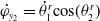
 $\dot{\varphi }_{x_2} = \dot{\theta }_{1}^r \mathrm{sin}(\theta _2^r)$
,
 $\dot{\varphi }_{y_2} = \dot{\theta }_{1}^r \mathrm{cos}(\theta _2^r)$
and
 $\dot{\varphi }_{z_2} = \dot{\theta }_{2}^r$
;
 $\dot{\varphi }_{x_3} = \dot{\theta }_{1}^r \mathrm{sin}(\theta _2^r+\theta _3^r)$
,
 $\dot{\varphi }_{y_3} = \dot{\theta }_{1}^r \mathrm{cos}(\theta _2^r+\theta _3^r)$
and
 $\dot{\varphi }_{z_3} = \dot{\theta }_{2}^r+\dot{\theta }_{3}^r$
;
 $\dot{\varphi }_{z_1}$
,
 $\dot{\varphi }_{z_2}$
and
 $\dot{\varphi }_{z_3}$
are the actuator velocities.
With relocated actuators.

Then, the following condition of the mass redistribution of the links is ensured:
 \begin{equation} I_{x_2} = I_{y_2} + m_3 l_{2}^{2} + m_2 r_{2}^{2} = I_{2}^{*} \end{equation}
 \begin{equation} I_{x_3} = I_{y_3} = I_{3}^{*} \end{equation}
Thus, the Lagrangian can be represented as follows:
 \begin{equation} L = \frac{1}{2}[I_{z_1}(\dot{\varphi }_{z_1})^2 + I_{2}^{*}(\dot{\varphi }_{z_1})^2 + (I_{z_2}+ m_3 l_{2}^{2} + m_2 r_{2}^{2})(\dot{\varphi }_{z_2})^2 + I_{3}^{*} (\dot{\varphi }_{1})^2 + I_{z_3}(\dot{\varphi }_{z_3})^2] \end{equation}
As a consequence of such a redistribution of moving masses, the motion equations become linear and decoupled:
 \begin{equation} \tau _1 = (I_{z_1}+I_{2}^{*}+I_{3}^{*})\ddot{\varphi }_{z_1} \end{equation}
 \begin{equation} \tau _2 = (I_{z_2}+ m_3 l_{2}^{2} + m_2 r_{2}^{2}) \ddot{\varphi }_{z_2} \end{equation}
 \begin{equation} \tau _3 = I_{z_3} \ddot{\varphi }_{z_3} \end{equation}
The nonlinear dynamic system is thus transformed into a double integrator model as obtained in the 2R spatial serial manipulator (6)–(8).
2.3. Motion generation via bang-bang profile
As discussed in ref. [Reference Arakelian, Geng and Lu23], to generate joint angular motion in the dynamically decoupled spatial serial manipulators, it is preferable to apply the “bang-bang profile” (Fig. 5), which enables reduction of the maximal input torque values.
Bang-bang motion profile is defined as:
 \begin{equation} \theta _d(t)=\left \{ \begin{array}{rcl} &\theta _d(t_0)+2\left(\dfrac{t}{t_f}\right)^2\theta _d(t_f), &\;{t_0\lt t\lt t_f/2}\\[12pt] &\theta _d(t_0)+\left [-1+4\left(\dfrac{t}{t_f}\right)-2\left(\dfrac{t}{t_f}\right)^2\right ]\theta _d(t_f), &\;{t_f/2\lt t\lt t_f}\\ \end{array} \right. \end{equation}
“Bang-bang” profile used for generation of motion in the dynamically decoupled 2R spatial serial manipulator.

3. Design of linear controller
3.1. Performance indices
For the controller design, performance indices are introduced to quantify and evaluate system performance. Two performance indices were considered in our case: the integral of the square of the error (ISE) and the maximum input torque. The ISE of the
 $i$
th link in the decoupled manipulator is defined as:
 \begin{equation} \mathrm{ISE_i} = \int _{t_0}^{t_f} e_i^2 \mathrm{d}t,\ i = 1,\cdots,n \end{equation}
where
 $e_i = \theta _i-\theta _{id}$
is the tracking error of the first link. The ISE discriminates between excessively over-damped and excessively under-damped systems. Tracking accuracy can be evaluated using this criterion. Another criterion introduced was the maximum input torque (MT), which represents input energy. The actuator capacity requirement also depends on the maximum input torque. Besides, the energy efficiency is affected by Joule effect, which describes the process where the energy of an electric current is converted into heat as it flows through a resistance. In electric motors, neglecting the friction, most part of the energy consumption is due to the loss by Joule effect. To evaluate the loss, a criterion is introduced as follows for the
 $i$
th link in the decoupled manipulator:
 \begin{equation} \mathrm{W_i} = \int _{t_0}^{t_f} \tau _i ^2 \mathrm{d}t,\ i = 1,\cdots,n \end{equation}
where
 $\tau _i$
is the actuator torque for the
 $i$
th link. For a DC motor, considering that the torque supplied by motor is proportional to the armature current, the criterion (20) is proportional to the energy consumption produced by Joule effect. It characterizes the energy that must be produced by the battery to allow the desired motion. Besides, the heat generated by Joule effect degrades the reliability of electrical systems components. For example, the results in ref. [Reference Jiao, Jermsittiparsert, Krasnopevtsev, Yousif and Salmani33] has revealed that the useful lifetimes of solder joints have been significantly decreased due to the Joule heating effect at high current densities. Therefore, the effect is undesirable and must be considered in controller design. Various straightforward control techniques are applied to track the bang-bang profile, and the influence on these performance indices will be investigated.
3.2. The performance of lead compensation
The primary function of the lead compensator is to reshape the frequency-response curve to provide a phase lead angle sufficient to offset the excessive lag phase associated with the components of the fixed system. The frequency-domain expression of the decoupled system is presented as follows:
 \begin{equation} G(\mathrm{s}) = \frac{I}{\mathrm{s}^{2}} \end{equation}
where the letter s, a complex variable, defines the Laplace transform operator; as mentioned above,
 $I$
can be obtained by the dynamic decoupling. For example, to each linear system (15)–(17) in the decoupled 3R manipulator,
 $I = (I_{z_1} + I_{2}^{*} + I_{3}^{*})$
for the first link,
 $I = I_{z_2}+ m_3 l_{2}^{2} + m_2 r_{2}^{2}$
for the second link, and
 $I = I_{z_3}$
for the third link. As all the dynamic systems are transformed into the similar structure (6)–(8) of double integrators, we will study the control performance about the first link with the biggest inertial moment, which has the lowest dynamic respond speed.
 $I=0.4\ \mathrm{kg m^2}$
for the first link in the decoupled 2R manipulator, and
 $ I = 57.60\ \mathrm{kg m^2}$
for the first link in the decoupled 3R manipulator. Since our new linear system, obtained by dynamic decoupling, was a double integrator model, a lead compensator could be used to stabilize the system by increasing the phase margin. A lead compensator in the following form will be used:
 \begin{equation} G_{c}(\mathrm{s}) = K_{c}\frac{T\mathrm{s}+1}{\alpha T\mathrm{s}+1} \end{equation}
where
 $K_{c}$
,
 $T$
, and
 $\alpha$
are the coefficients determined with the maximum phase lead angle and the cutoff frequency. Note however that the system’s dynamic characteristics need to be modified by increasing the cutoff frequency, which increases the dynamic response speed to track the bang-bang profile. The gain crossover frequency of the decoupled system is therefore increased to
 $89.44\ \mathrm{rad/s}$
for the first link. This implies an increase in the speed of response. Then, we assumed that the necessary maximum phase lead angle
 $\phi _m$
is
 $70^{\circ }$
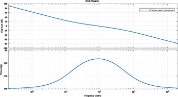
, and therefore the coefficients in the lead compensator, could be determined. The Bode plot of the compensated system is presented in the Fig. 6.
As observed in the Bode plot, the maximum phase lead margin was increased to
 $70^{\circ }$
at the modified gain crossover frequency
 $89.44\ \mathrm{rad/s}$
, which improved the asymptotic stability. To see the tracking performance and the input torque, the simulation was carried out in Matlab. The value of the time step was set at
 $1 \times 10^{-5}\ \mathrm{s}$
. The simulation results are presented in the Figs. 7–10.
It is obvious that the systems (2R and 3R) with the modified gain crossover frequency and
 $70^{\circ }$
phase lead angle is capable of tracking the desired bang-bang profile trajectory. For example, in the decoupled 3R manipulator, the ISE is
 $8.29\times 10^{-2}$
 $\mathrm{rad^2 s}$
and the maximum torque is
 $4.78\times 10^{2}$
Nm. The energy consumption produced by Joule effect is
 $1.3252\times 10^{5}$
 $\mathrm{rad^2 s}$
 $\mathrm{N^2 m^2 s}$
. In addition, the Tables II and III with a variety of phase lead angles were created to investigate the influence of different phase lead angles on three criteria in both 2R and 3R decoupled manipulators.
Results of different phase lead angles in the decoupled 2R spatial serial manipulator.

Frequency domain response with
 $70^{\circ }$
phase lead compensator.

Trajectory tracking of lead compensator in the decoupled 2R spatial serial manipulator.

Torque generation of lead compensator in the decoupled 2R spatial serial manipulator.

Trajectory tracking of lead compensator in the decoupled 3R spatial serial manipulator.

Results of different phase lead angles in the decoupled 3R spatial serial manipulator.

Torque generation of lead compensator in the decoupled 3R spatial serial manipulator.

The table shows that the ISE is diminished, and the maximum torque increased when the phase lead angle is increased. In application, a large phase lead angle is required to lower the actuator capacity and energy consumption. However, for a system requiring high tracking accuracy, a small phase lead angle is needed. Obviously, there is a trade-off between the tracking accuracy and input energy efficiency, which also means that the required performance can be achieved by adjusting the phase lead angle, which facilitates the design of the robot manipulator controller. To achieve a more satisfactory control performance, full-state feedback method is considered in the following parts.
3.3. The performance of linear quadratic regulator
Since the double integrator model system is unstable, the control technique should increase the stability of the system. Therefore, the speed of response and tracking error requirement should be improved to track the bang-bang profile. Linear quadratic regulator (LQR) is a powerful control technique, which stabilizes and operates a linear dynamic system by minimizing a given cost function. In order to implement a LQR controller, a linear time-invariant (LTI) dynamic system must be available, which has already been obtained by the dynamic decoupling, and the system must be completely controllable. We assumed that all state variables were measurable and also available for feedback in our system. The controllability matrix is given by:
 \begin{equation} \textbf{C} = \begin{bmatrix} \boldsymbol{{B}} & \boldsymbol{{AB}} & \boldsymbol{{A}}^{\textbf{2}}\textrm{B}&\ldots &{\boldsymbol{{A}}^{\boldsymbol{{n}}-1}\boldsymbol{{B}}} \end{bmatrix}= \begin{bmatrix} 0 & 1/I\\ 1/I & 0 \end{bmatrix} \end{equation}
Since the control matrix C of the state space equation obtained has full row rank 2, this decoupled dynamic system is controllable. LQR algorithme aims to minimize the quadratic cost function as follows:
 \begin{equation} \int _{0}^{\infty } (\boldsymbol{{x}}^{\top }\boldsymbol{{Q}}\boldsymbol{{x}}+\boldsymbol{{u}}^{\top }\boldsymbol{{R}}\boldsymbol{{u}}) {\textbf{d}\boldsymbol{{x}}} \end{equation}
where
 $Q$
and
 $R$
are the weights related to the system state error (angle and angular velocity) and the control input (motor torque), respectively. The appropriate selection of
 $Q$
and
 $R$
determines the control performance. The optimal control law to minimize the quadratic cost function is given by:
 \begin{equation} {\boldsymbol{{u}} = -\boldsymbol{{Kx}}} \end{equation}
where
 \begin{equation} \boldsymbol{{K}} = \boldsymbol{{R}}^{-\textbf{1}} \boldsymbol{{B}}^{\boldsymbol\top } \boldsymbol{{P}} \end{equation}
and
 $P$
is found by solving the continuous time algebraic Riccati equation:
 \begin{equation} {\boldsymbol{{A}}^{\boldsymbol\top } \boldsymbol{{P}} + \boldsymbol{{PA}} - \boldsymbol{{P}} \boldsymbol{{B}} \boldsymbol{{R}}^{-\textbf{1}} \boldsymbol{{B}}^{\boldsymbol\top } \boldsymbol{{P}} + \boldsymbol{{Q}} = \textbf{0}} \end{equation}
The design steps may be stated as follows:
-
1. Solve equation, the reduced matrix Riccati equation, for the matrix
$P$
-
2. Substitute this matrix
$P$
into equation. The resulting matrix
$K$
is the optimal one.


The simulation was carried out in Matlab software with
 $I = 0.4 \ \mathrm{kg m^2}$
(the first link with lower frequency) and the time step set at
 $1 \times 10^{-5}$
s. By using the steps mentioned above, the optimal control gains
 $K_1$
and
 $K_2$
were calculated as
 $K_1 = 3464.10$
and
 $K_2 = 634.64$
. The values of
 $\boldsymbol{{Q}}$
and
 $\boldsymbol{{R}}$
were initialized as follows for the control of the first link:
 \begin{equation} \boldsymbol{{Q}} = \begin{bmatrix} 600,000 & 0\\ 0 & 20,000 \end{bmatrix}, \boldsymbol{{R}} = \begin{bmatrix} 0.05 & 0\\ 0 & 0.05 \end{bmatrix} \end{equation}
The initial and final values of the rotating angles were as follows:
 $\theta _i = 0^{\circ }$
and
 $\theta _f = 90^{\circ }$
. The tracking performance and the input torque of the decoupled 2R manipulator were obtained in the Figs. 11 and 12.
The simulation has also been carried out in the decoupled 3R manipulator (
 $I = 57.60 \ \mathrm{kg m^2}$
) with
 $K_1 = 109,540$
and
 $K_2 = 40,160$
. The Figs. 13 and 14 present the simulation results.
Trajectory tracking of LQR in the decoupled 2R manipulator.

Torque generation of LQR in the decoupled 2R manipulator.

Trajectory tracking of LQR in the decoupled 3R manipulator.

Torque generation of LQR in the decoupled 3R manipulator.

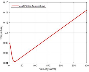
Joint friction curve.

From the simulation results, it was observed that in the decoupled dynamic system, LQR results in excellent control performance by the bang-bang profile. For example, in the 3R decoupled manipulator, the ISE is
 $0.2144\ \mathrm{rad^2 s}$
and the maximum torque is
 $3.64\times 10^{5}$
Nm. The energy consumption produced by Joule effect is
 $1.3109\times 10^{5}$
 $\mathrm{N^2 m^2 s}$
. From the data obtained above, it can be seen that LQR controller performs better than lead compensator in terms of energy consumption. However, these linear controllers did not take the parameter uncertainty and external unknown disturbances into account in the control process, which may destabilize the decoupled dynamic system.
4. Parameter uncertainty and external disturbance
Generally, not every dynamic system is exactly the same as what we considered in the design process. Parameter uncertainty and unknown external disturbances take place in many practical problems, which results in the degradation of stability, accuracy, energy consumption, etc. These factors must be taken into account in the design of controller. For the decoupled manipulators designed in Section 2, a variation of inertial values may exist in the dynamic model. Linear control techniques used previously cannot attain perfect control performance. Further, the unknown external disturbances are another thing taken into account when designing controllers for the spatial serial manipulators, which will degrade the stability or tracking accuracy of the control system. Generally, Friction has been considered as the major cause of low efficiency, poor reliability, and durability of mechanical system, which is a complex and nonlinear phenomenon and occurs at the interface of components (prismatic and revolute joints) in relative motion. According to Haessig Jr and Friedland [Reference Haessig and Friedland34], “Friction is the nemesis of precision control.” A lot of friction models have been proposed in the literature. They are mainly classified into two groups: dynamic friction models and static friction models. The dynamic models, like Dahl model or LuGre model [Reference Muvengei, Kihiu and Ikua35], can capture more friction characteristics, but it is not easy to applicate due to the model complexity. To model the friction disturbance, a static friction model considering Stribeck effects and viscous effects [Reference Bittencourt and Gunnarsson36] was adopted in our case because of its simple implementation and acceptable accuracy. Considering the nonlinear friction, the plant is represented as follows:
 \begin{equation} I\ddot{\theta } = u+ \tau _f(\dot{\theta }) \end{equation}
where the joint friction
 $\tau _f(\dot{\theta })$
can be defined as follows:
 \begin{equation} \tau _f(\dot{\theta }) = (F_c+F_s e^{-\left | \dfrac{\dot{\theta }}{\dot{\theta }_s}\right |^\beta })\mathrm{sign}(\dot{\theta })+F_v\dot{\theta } \end{equation}
where
 $F_c$
is the Coulomb friction,
 $F_s$
is the standstill friction parameter,
 $\dot{\theta }_s$
is the Stribeck velocity, and
 $\beta$
is the exponent of the Stribeck nonlinearity.
 $F_v$
represents the viscous friction. The curve of the joint friction
 $\tau _f(\dot{\theta })$
is presented in the Fig. 15 with the parameters used in ref. [Reference Bittencourt and Gunnarsson36]:
 $F_c = 3.40 \times 10^{-2} \ \mathrm{Nm}$
;
 $F_s = 4.60 \times 10^{-2}\ \mathrm{Nm}$
;
 $F_v = 3.68 \times 10^{-4}\ \mathrm{Nm/(rad/s})$
;
 $\dot{\theta }_s=10.68\ \mathrm{rad/s}$
;
 $\beta = 1.93$
.
In the following sections, different control techniques are presented and used to stabilize the decoupled dynamic system in the presence of parameter uncertainty and external disturbances.
4.1. The performance of model-reference adaptive control
The parameter uncertainty or variation occurs in many practical problems. For instance, robot manipulators carry out their tasks such as “pick and place” with inaccurate inertial parameters. It may cause inaccuracy or instability for control systems. In our case, thanks to the dynamic decoupling, the 2R and 3R spatial manipulator models have been simplified as a double integrator. However, it is very strict to assume that the inertial parameters of the dynamically decoupled manipulator are the exactly same as we know in the design process. To resolve the problem, model-reference adaptive control (MARC) has been proposed in ref. [Reference Slotine and Li37], which can be adopted for the decoupled dynamic system. An adaptation mechanism in MARC aims to adjust the parameters in the control law so that the perfect tracking performance can be achieved [Reference Slotine and Li37]. The MRAC law is presented as follows:
 \begin{equation} u = \hat{I}(\ddot{\theta }_d-2\lambda \dot{\hat{\theta }}-\lambda ^2\hat{\theta }) \end{equation}
where tracking error
 $\hat{\theta } = \theta -\theta _d$
;
 $\lambda$
is the positive constant chosen to reflect the performance specification.
 $\hat{I}$
is defined as the estimate of inertial. The following update law is used to adjust the parameter:
 \begin{equation} \dot{\hat{I}} = -\gamma v s \end{equation}
where
 $\gamma$
is a position constant called the adaptation gain;
 $v = \ddot{\theta }_d-2\lambda \dot{\hat{\theta }}-\lambda ^2\hat{\theta }$
. The combined tracking error
 $s$
is defined as:
 \begin{equation} s = \dot{\hat{\theta }}+\lambda \hat{\theta } \end{equation}
The equations above present an adaptation mechanism based on system signals. The proof of the global asymptotic stability is demonstrated in ref. [Reference Slotine and Li37] with the Lyapunov theory. The interested reader may refer to ref. [Reference Slotine and Li37] for further details. The simulation is carried out in Matlab with the following parameter. For the decoupled 2R manipulator:
 $\gamma _1=2$
;
 $\lambda _1=50$
; and
 $\hat{I}_1(0) = 0.4$
 $\mathrm{kgm^2}$
. The real inertial value is
 $0.5$
 $\mathrm{kgm^2}$
. For the decoupled 3R manipulator:
 $\gamma _2=200$
;
 $\lambda _2=50$
; and
 $\hat{I}_2(0) = 57.60$
 $\mathrm{kgm^2}$
. The real inertial value is
 $72$
 $\mathrm{kgm^2}$
. The time step is set as
 $1 \times 10^{-5}$
s.
As shown in the Figs. 16 and 17, there is no significant difference between the desired trajectory and the trajectory generated by the MRAC. At the beginning of the control process in the Figs. 18 and 19, an increasing torque is generated due to the wrong inertial information but then the torque generation becomes almost the same as the bang-bang profile by adjusting the inertial value during the process. The control performance indices were calculated from the simulations:
Trajectory tracking of MRAC in the decoupled 2R manipulator.

Trajectory tracking of MRAC in the decoupled 3R manipulator.

Torque generation of MRAC in the decoupled 2R manipulator.

As can be seen from the Table IV, MRAC consumes less energy than LQR controller in the decoupled dynamic system but the maximum torque is increased a little. Besides, the tracking accuracy of MRAC is much better than LQR controller. It should be noted that MARC could maintain a high tracking accuracy in the presence of parameter uncertainty, which is attractive for the design of controller.
4.2. The performance of modified twisting controller
A lot of nonlinear controllers have been proposed in the literature to overcome the external disturbances [Reference Slotine and Li37]. In the friction model (30), it should be noticed that there always exist the discontinuous terms
 $\mathrm{sign}(\dot{\theta })$
. Attributed to these discontinuous terms of friction, the continuous control algorithms are unable to stabilize the dynamic system. Thus, the discontinuous controllers are brought into sight to resolve the stability problem. Among them, the twisting algorithms are well recognized for the robustness properties and finite time stability. The controllers, which have switching terms, are capable of forcing the dynamic system to the zero dynamics of error in spite of the external disturbances. However, in the twisting controller, the chattering occurs in the dynamics system due to the important switching gain and results in low reliability of mechanical systems. Yury Orlov has proposed a modification of the twisting controller to resolve the problem, which aims to avoid the undesired chattering phenomenon appearing in the closed loop when driven by an important switching input. The main advantages of this control are to ensure a convergence in finite time and to be continuous. The effectiveness of the proposed method was demonstrated for a double integrator model [Reference Orlov, Aoustin and Chevallereau38]. The feedback law is stated as follows:
 \begin{equation} u = -\mu \left | e_2 \right |^\epsilon \mathrm{sign}(e_2)-v\left | e_1 \right |^{\dfrac{\epsilon }{2-\epsilon }}\mathrm{sign}(e_1) \end{equation}
where
 $e_1 = x_1-x_{1d}$
and
 $e_2 = x_2-x_{2d}$
. Parameters
 $v\gt \mu \gt 0$
and
 $\epsilon \in [0,1)$
are proposed to globally stabilize the double integrator. Suppose that the external disturbance friction satisfies the growth condition:
Results of two controllers in the presence of parameter uncertainty.

Torque generation of MRAC in the decoupled 3R manipulator.

Trajectory tracking of modified twisting controller in the decoupled 2R manipulator.

Trajectory tracking of modified twisting controller in the decoupled 3R manipulator.

 \begin{equation} \left | \tau _f(\dot{\theta }) \right | \leq \mu _0 \left | e_2 \right |^\epsilon \end{equation}
where
 $\mu _0$
is the upper bound of the external disturbance. According to ref. [[Reference Orlov, Aoustin and Chevallereau38], Theorem 1], for any disturbance
 $w$
satisfying the growing condition, the continuous closed-loop system is globally asymptotically stable if
 $\mu _0 \leq \mu$
. The proof is given in ref. [Reference Orlov, Aoustin and Chevallereau38] by applying the Lyapunov function and invariance principle. The simulation is carried out in Matlab with the following parameters of controller:
 $\mu _1 = 1000$
,
 $v_1 = 1500$
, and
 $\epsilon _1=0.8$
for the 2R decoupled maniplator, and
 $\mu _2 = 140,000$
,
 $v_2 = 230,000$
, and
 $\epsilon _2=0.8$
for the 2R decoupled maniplator. In terms of friction, the parameters in the decoupled 2R manipulator are set to be:
 $F_c = 3.40 \times 10^{-2}\ \mathrm{Nm}$
;
 $F_s = 4.60 \times 10^{-2}\ \mathrm{Nm}$
;
 $F_v = 3.68 \times 10^{-4}\ \mathrm{Nm/(rad/s)}$
;
 $\dot{\theta }_s=10.68\ \mathrm{rad/s}$
; and
 $\beta = 1.93$
. In the decoupled 3R manipulators, the friction is supposed to be 30 times of the friction in the decoupled 2R manipulator. The errors of the moment of inertia in the previous section are also considered in the decoupled manipulator. In the simulation, the time step is set as
 $1 \times 10^{-5}$
s.
As shown in the Figs. 20 and 21, no significant tacking differences were found after the rise time between the desired trajectory and the trajectory generated by the modified twisting controller. Even if there exists the discontinuous terms in the friction model (described by sign functions without any approximation in the simulation), it can be observed from the Figs. 22 and 23 that the torque generated by the modified twisting controller is close to the ideal bang-bang profile except the discontinuous points. It has been shown in the Figs. 24 and 25 that the maximum difference after the rise time between the actuator torque and the ideal torque is
 $0.0626$
and
 $7.1040\ \mathrm{Nm}$
(both below
 $2 \%$
of the ideal torque) for the decoupled 2R and 3R spatial serial manipulators. The result shows that an appropriate choice of
 $\varepsilon$
in the modified twisting controller attenuates the chattering effects. Then, the control performance indices could be calculated from the simulation:
Results of different controllers in the presence of joint friction.

Torque generation of modified twisting controller in the decoupled 2R manipulator.

Torque generation of modified twisting controller in the decoupled 3R manipulator.

As can be seen from the Table V, the best control performance is attained with the modified twisting controller, which consumes less energy and maintains high tracking accuracy. The simulation results demonstrate that the modified twisting controller is effective to stabilize the decoupled dynamic system in the presence of parameter uncertainty and external disturbances.
Difference between the actuator torque and the ideal torque in the decoupled 2R manipulator.

Difference between the actuator torque and the ideal torque in the decoupled 3R manipulator.

5. Conclusion and perspectives
The control of robot manipulators for high-performance and high-speed tasks has always been a challenge for control engineers. Nonlinear control has been developed, but it encounters difficulties such as tracking inaccuracy at high speed and a heavy computational burden. It may be difficult to obtain satisfactory control performance in a very complex dynamic system. To resolve this problem, a new mechatronics approach is proposed to meet the demand for control performance. Rather than concentrating on the design of the control algorithm, this approach focuses on redesigning the mechanical structure to obtain a linear and decoupled dynamic system. This offers greater convenience for controller design. The arrangement of centers of mass and inertia redistribution for the links were described to obtain the decoupled and linear dynamic equations for the manipulator. It was demonstrated that the input torques in the 2R and 3R dynamically decoupled manipulators we obtained are directly proportional to the input angular accelerations. A test of different controllers with simple structures were carried out for the decoupled system. The classical linear control techniques LQR and lead compensation were adopted to track the desired bang-bang profile trajectory. Then, in the presence of parameter uncertainty and external disturbances, adaptive control MRAC and modified twisting control were adopted to stabilize the decoupled system asymptotically. The application of linear control techniques is straightforward and effective for the decoupled system. In the presence of parameter uncertainty and external disturbances, the MRAC and the modified twisting controller perform well for the double -integrator model. The results of the simulations demonstrate that the proposed method reduces the computational burden and provides an improved control performance in tracking accuracy, energy consumption, and maximum input torque. In the future, the observer technique will be developed in the control feedback loop, and its control performance will be evaluated. The experiments will be designed to validate the proposed approach. Besides, we will also explore the possibility of applying the approach in the parallel robots. Therefore, we think the proposed solutions are of great interest to the scientific community.
Author contributions
Yaodong Lu and Yannick Aoustin conceived and designed the study. Yaodong Lu conducted and analyzed the numerical experiments. Yaodong Lu, Yannick Aoustin, and Vigen Arakelian wrote the article.
Financial support
This work was supported by the China Scholarship Council [Grant Number: 202008070129].
Conflicts of interest
The authors declare none.