Introduction
Fabry–Pérot (FP) antennas, which are also known as partially reflecting surface (PRS) antennas, along with resonant cavity antennas, FP resonator antennas, and electromagnetic band gap resonator antennas have received significant attention recently because of their simple design and highly directional radiation [Reference Lovat, Burghignoli and Jackson1–Reference Jackson, Burghignoli, Lovat, Capolino, Chen, Wilton and Oliner5]. Pioneered by von Trentini in 1956 [Reference Lovat, Burghignoli and Jackson1], the performance of FP antennas has been improved subsequently through design optimization [Reference Zeb, Ge, Esselle, Sun and Tobar6–Reference Sun, Chen, Zhang, Chen and See9], theoretical interpretation [Reference Jackson, Burghignoli, Lovat, Capolino, Chen, Wilton and Oliner5, Reference Hosseini, De Flaviis and Capolino10], and optimization analysis [Reference Feresidis and Vardaxoglou2–Reference Jackson and Oliner4]. FP antennas offer high gain, multi-band and wideband operation [Reference Zeb, Ge, Esselle, Sun and Tobar6], CP [Reference Qin, Gao, Wei, Luo, Mao, Gu, Xu and Li8], reconfigurability [Reference Guzmán-Quirós, Weily, Gómez-Tornero and Guo11–Reference Huang, Pan, Ma and Luo13], and have a low profile [Reference Sun, Chen, Zhang, Chen and See9] while reducing the radar-cross-section (RCS) [Reference Jiang, Xue, Li, Ren and Cao7]. These properties of FP antennas make them suitable for sensors and communication systems in stealth platforms.
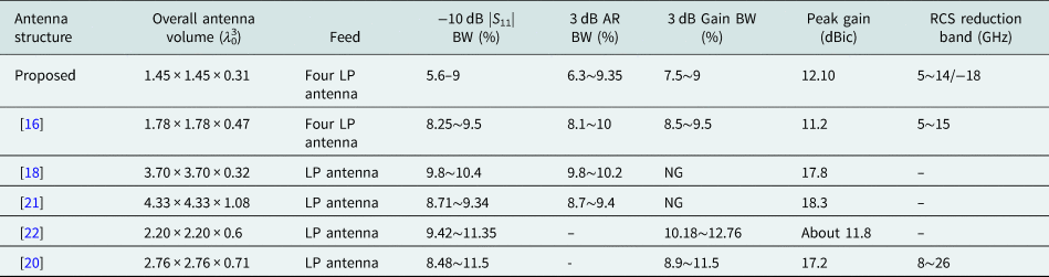
Metasurfaces are used for bandwidth expansion and RCS reduction in FP antennas because they are capable of performing electromagnetic wave modulation. One research effort designed FP antennas with low RCS using resistor-loaded PRS and absorbing surfaces [Reference Jiang, Xue, Li, Ren and Cao7, Reference Huang, Pan, Ma and Luo13]. FP antennas designed using absorbent surfaces had greater reductions in the RCS, but they were linearly polarized (LP) and difficult to fabricate due to the large number of welded resistors. Polarization-conversion metasurfaces (PCMs) have also been employed to reduce the RCS [Reference Zheng, Gao, Zhou, Cao, Yang, Li and Li14–Reference Zheng, Gao, Cao, Li and Li17]. A PCM with a reflection phase difference of 180 ± 30° was etched into a single-layer dielectric substrate in a checkered pattern. Following destructive interference, this method decreased RCS over a wide band and increased gain. However, these improvements were limited because the cross-polarization of reflective waves transmitted through the PCM was not reduced. Another proposal described a 4 × 4 PCM array consisting of a metasurface cell with a three-layer metal plane separated by two substrates to offer CP and high gain [Reference Li, Liu, Jia and Guo16]. However, reducing the cross-polarization of reflected waves by the PCM was not taken into account. Thus, this method had average axial ratio (AR) values larger than those of our proposed antenna, with lower peak gain in spite of its larger size. Another method has implemented a high-gain circularly polarized FP receiver–transmitter with PCM slot antennas by adjusting the location of metal-via and trimming the corners of the square patch antenna to obtain high reflectivity, satisfactory transmission magnitude, and the desired phase difference [Reference Xie, Wang, Li, Liang and Gao18]. However, this method resulted in a narrow circularly polarized bandwidth and did not consider RCS reduction.
We propose an FP antenna incorporating a checkered PCM with a metal ring sandwiched between the top and bottom substrates to form a sandwich compound. We etch our proposed PCM into the dielectric substrate of the FP antenna in a checkered pattern and adjust the transmissive coefficients of the PCM (Txx and Tyx) to obtain a 90° phase difference and equal magnitudes. We manufacture our PCM using materials with low cross-polarization of reflective waves.
The rest of this paper is organized as follows. Section “Design of the proposed PCM” details the design of our proposed PCM. The section “Analysis and design of the proposed FP antenna” presents the design of the FP antenna using this PCM. The section “Simulated and measured results” presents our simulation and measurement results. The last section provides our conclusions.
Design of the proposed PCM
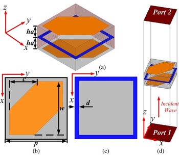
Figure 1 shows a unit cell consisting of a pair of square patch antennas with cut corners and a metal sandwiched between them. The antenna was placed on a 6 mm × 6 mm substrate (ɛ r = 4.4, tan δ = 0.02) of thickness d. Figure 1(d) shows a simulation model of the unit cell in High Frequency Structure Simulator (HFSS).
(a) 3-D sketch of the PCM, (b) top-view of the patch antenna with trimmed corners, (c) top view of the metal, and (d) HFSS model of the unit cell

According to FP antenna theory, the cavity resonance between the ground of the source antenna and the PCM is excited when the FP resonant condition in equation (1) is satisfied:

where ϕ PCM and ϕ GND are the reflection phases of the ground plane and PCM, respectively; λ 0 is the free space wavelength at the operating frequency, and hc is the height of the cavity. Thus, a maximum directivity at the broadside of the FP antenna occurs because waves exit the cavity in phase. A low profile was achieved by setting N to 0, operating the cavity at first resonance. We then adjust the PCM reflection phase ϕ PCM to satisfy equation (1). We calculate the boresight directivity of the antenna using equation (2) for the emitted, in-phase waves assuming a finite size for the resonant cavity:

In equation (2), R is the reflection magnitude of the PCM. From this formula, we know that the boresight directivity is higher when R increased for Dr is an increasing function of R. The directivity is optimal and maximum when R is about 0.9 [Reference Xie, Wang, Li, Liang and Gao18].
Other studies have designed a novel composite metasurface to reduce the cross-polarization of reflective waves traveling through the medium, leading to a large AR [Reference Guo, Cao, Gao, Yanag and Jidi19]. Therefore, we considered the reduction of cross-polarization to ensure high gain and wideband CP in the antenna while designing our PCM.
We complete our design with a few remaining steps. First, to achieve CP, we trim a pair of corners based on dual conventional rectangular patches, where an equal magnitude and a 90° phase difference can be generated by tuning the transmission coefficients Txx and Tyx. Second, to reduce the cross-polarization component of the reflected waves, we adopt a metal ring sandwiched between layers to improve the gain and enhance the wideband CP. We then form an FP cavity with the source patch antenna being designed, performing an LP to CP transformation of transmitted waves from the cavity to improve the gain further. Finally, we arrange the checkered antenna array using sequential rotation to reduce the RCS of the proposed antenna.
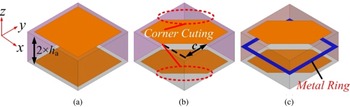
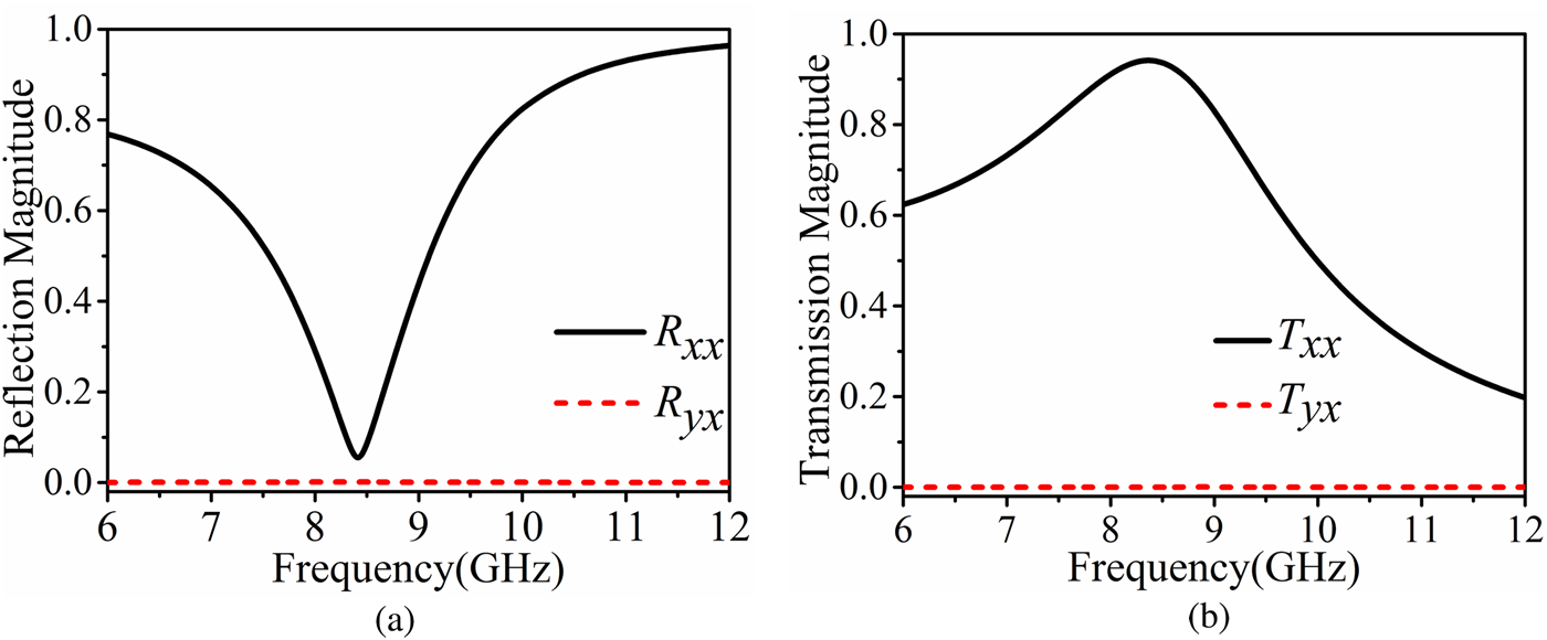
To design our unit cell, we modify the one shown in Fig. 2 to arrive at the one in Fig. 1. Referring to the simulation results in Fig. 3, the initial unit cell did not circularly polarize the waves, as indicated by the transmissivity and reflectivity of cross-polarization (Tyx, Tyx) being nearly zero. This suggests that the original metasurface is incapable of converting polarization.
(a) Initial square patch antennas, (b) corner-cut square patch antennas (ele.b), and (c) metal sandwiched by corner-cut square patch antennas (proposed ele.)

Simulated S parameters of the initial square patch antennas: (a) reflection magnitude and (b) transmission magnitude

The metasurface requires low cross-polarization to maintain the gain and bandwidth improvements [Reference Guo, Cao, Gao, Yanag and Jidi19]. The metasurface also requires a high transmission magnitude. We require two countermeasures to increase the reflectivity of the metasurface.
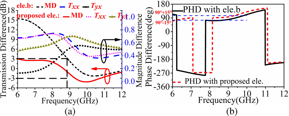
Referring to Fig. 2(b), we cut the corners of the square patch antennas to make Txx and Txy equal and create a 90° phase difference. The simulation results in Fig. 4 show that trimming the corners significantly improves the cross-polarization of transmissivity (Tyx) compared to the uncut square patch antenna. This means that the co-polarized transmissivity (Txy) and cross-polarized transmissivity (Txx) are nearly equal.
(a) Transmission magnitudes versus frequency for ele.b and proposed ele. and (b) phase difference versus frequency for ele.b and proposed ele.

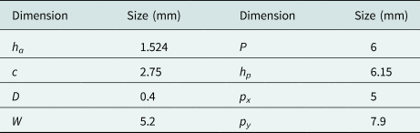
We achieve the 90° phase difference in Txy and Txx by adjusting the length of the corner cut c to 3 mm. This length led to a phase difference variance of 15° in different frequency bands as shown in Fig. 4(b). The 3 mm corner cut length c ensures Txy and Txx are nearly equal, with a variation of ±3 dB. Txy and Txx have a phase difference of 90° and demonstrate that linear-to-circularly polarized conversion results and that the corner cuts radiate circularly polarized waves (Table 1).
Optimal dimensions of the proposed FP patch antenna

As shown in Fig. 2(c), we sandwich a metal ring between the top and bottom substrate to reduce cross-polarization and increase gain in the antenna. Figure 4 shows the transmission magnitude, magnitude difference, and phase difference, with and without the embedded metal (element b and proposed element, abbreviated as ele.b and proposed ele. in the related figures). Figure 4 demonstrates that linear-to-circular polarization conversion occurs in the 6–12 GHz range of wideband frequencies with the corner-cut square patch antennas.
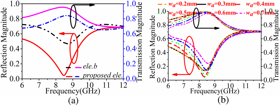
Figure 5(b) shows a plot of the transmission and reflective magnitudes versus frequency for different metal widths wa. The reflective magnitude of cross-polarization was nearly zero at 8.5 GHz with wa of 0.4 mm, ensuring high gain and CP in the proposed antenna, as shown in Fig. 5(a). Figure 5(b) also shows that the highest gain occurs at 8.5 GHz.
(a) Reflection magnitude of cross-polarization and (b) effects of metal width wa on the S parameters

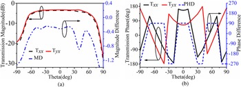
Figure 6 shows a plot of transmission coefficients versus the incident angle at 8.5 GHz in the xoz plane. The properties of the proposed PCM change slightly when an oblique incident wave passes through. The properties of the proposed PCM rapidly deteriorate once the incident angle exceeds 60°. Thus, we hold the incident angle stable to maintain the performance of the PCM.
(a) Transmission magnitude versus incident angle at 8.5 GHz, and (b) phase difference versus incident angle at 8.5 GHz

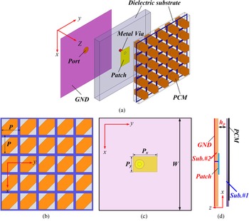
We adopt an off-center microstrip patch antenna (MPA) as the radiation source for the antenna. The MPA feeder is composed of an FR4 substrate (ɛr = 4.4, tan δ = 0.02) with a thickness of 3 mm, as described in Figs 7(c)–7(d). We print the ground plane and radiation patch at the bottom and top of the substrate, respectively.
Proposed PCM with MPA: (a) schematic, (b) top view, (c) bottom view, and (d) side view

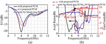
We simulate the FP antenna with and without the proposed PCM, and with no metal-ring PCM, as shown in Fig. 8. It can be seen obviously that bandwidth enhancement and gain improvement of patch antenna would be achieved by the proposed PCM adopted, though a nearly zero AR point occurred when no metal-ring PCM was utilized in this design, which is quite narrow. Resonance achieves the gain enhancement in right-hand circular polarization (RHCP) antennas with PCM, with a maximum improvement of 2.5 dBic. According to other design guidelines, the resonance in the cavity of the FP antenna should satisfy the requirements for y- and x-polarizations [Reference Qin, Gao, Wei, Luo, Mao, Gu, Xu and Li8]. The reflection coefficients of the PCM should also satisfy the requirements for y- and x-polarizations [Reference Sun, Chen, Zhang, Chen and See9]. The height of the resonance cavity (H) is given by equation (3):

where n is an integer (n = 0, 1, 2 …), H is the height of the resonance cavity, and c is the speed of light in a vacuum. Φ1x and Φ2y are the phases of the reflection coefficient in the y and x directions of the ground, respectively.
(a) |S11| with and without PCM superstrate and (b) AR and gain with and without PCM superstrate

It is important that the sum of the phases of the reflection coefficients be equal in both directions to satisfy the resonance requirements of the y- and x-polarizations, as expressed in equation (4):

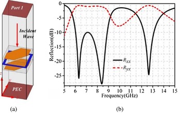
where Φ2x and Φ1y are the phases of the PCM. We assume that both polarizations use the same value of n. The phases of the reflection coefficient in the ground of the antenna are equal to π, i.e. Φ1x = Φ1y = π. This is required to obtain an FP antenna with high gain and circular polarization. As explained elsewhere, the symmetrical structure of the proposed PCM with respect to the 45° diagonal, the reflection magnitudes and phases have a similar curve in the x and y directions and the reflection phases, proving that PCM can be used to construct resonance cavities [Reference Li, Liu, Jia and Guo16]. PCM plays a role in transmission, which explains the backscattering in the antenna. We employ a perfect electrical conductor (PEC) ground to simulate the PCM unit cell since both the ground and radiation patches of the source antenna are PECs. The distance between the unit cell and PEC was optimized to 6.15 mm. Through adopting simulated model in HFSS as depicted in Fig. 9(a), Fig. 9(b) shows the cross- and co-polarization reflections in the PCM unit cell with PEC ground. The reflection coefficients of cross-polarization are consistent, while those of co-polarization were lost at 15 GHz. We etch the PCM into the substrate with a checkered pattern to reduce RCS and wideband operation [Reference Li, Liu, Jia and Guo16]. The extent of the RCS reduction depends on the reflective properties of the PCM. Referring to Fig. 8(b), RHCP radiation is present when the PCM is etched into the square patch antenna. Left-hand circular polarization (LHCP) radiation can be gathered by replacing a PCM with a mirror.
(a) Proposed model in HFSS, and (b) cross-polarization and co-polarization reflections

Analysis and design of the proposed FP antenna
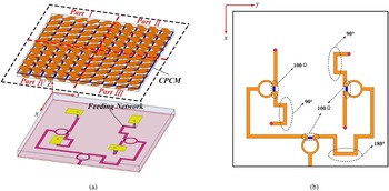
As shown in Fig. 10, we obtain a 2 × 2 FP antenna array arrangement using sequential rotation. Referring to Fig. 10, there are four sequential rotation orders, labeled parts I, II, III, and IV. As indicated in Fig. 10(b), we design a Wilkinson feeding network with four ports and a 90° phase difference for the proposed FP antenna array.
(a) Schematic of FP antenna with checkered PCM, and (b) Wilkinson feeding network

LHCP and RHCP radiations reduce gain and produce four grating lobes in the direction of the boresight if two kinds of PCMs are excited at similar points [Reference Liu, Liu, Jens, Zhao and Kong20]. To mitigate this kind of interference, we select an RHCP antenna array with circularly polarized radiation and a sequentially rotated feeding network as the source antenna. The feeding network excites four orthogonal RHCPs and is printed at the bottom of the 0.5 mm substrate. The ambient RHCPs are excited using a 90° phase difference. RHCP waves are produced when LP waves pass through the PCM or mirror. Gain degradation does not occur in the direction of the boresight. The selected source antenna ensures scattering without reducing radiation. RHCP radiation can be produced without PCM; however, the antenna with PCM possesses a broader AR bandwidth because higher polarization occurs by replacing the four LP elements with four circularly polarized elements. RHCP gain could be improved further through operational frequency. Wideband operation and low RCS are enabled by the checkered PCM. There are several similarities between the x- and y-polarized incident waves and RCS reduction.
Simulated and measured results
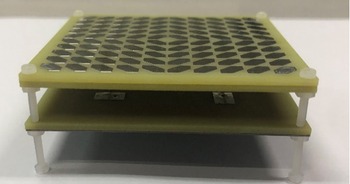
To evaluate our design, we simulated, fabricated, and tested our proposed FP antenna design. Figure 11 shows the sample fabricated prototype. As Fig. 11 shows, the substrates of the fabricated prototype were extended by 6 mm compared to the simulation model and fastened with a 3.5 mm subminiature version A connector. The fabricated array had dimensions of 66 mm × 66 mm × 12.65 mm.
Fabricated sample of the proposed FP antenna

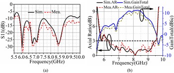
As shown in Figs 12(a) and 12(b), our antenna had a 10 dB bandwidth at 3.4 GHz (5.6–9 GHz) and a 3 dB AR bandwidth at 3.3 GHz (6.2–9.5 GHz), where the bandwidth enhancement and gain improvement were obtained, compared to the PCM-based antenna element. It can be explained by the application of sequential rotation technical on the 2 × 2 antenna array, which can improve radiation of antenna array significantly.
(a) Simulated and measured |S11| and (b) simulated and measured broadside gain and AR

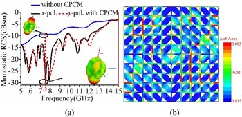
Figure 13(a) shows a plot of RCS reduction versus frequency. The proposed antenna achieved wideband operation and low RCS between 5 and 14 GHz, representing 94.7% of the bandwidth. RCS reduction reached −18 dBsm. We classified the insert that provided the reflective energy into four lobes, reducing RCS significantly. The distribution of scattering is shown in Fig. 13(b). Parts I, II, III, and IV had different resonances, which led to the efficient phase difference between them.
(a) RCS reduction versus frequency with and without PCM and (b) distribution of scattering at 7.5 GHz

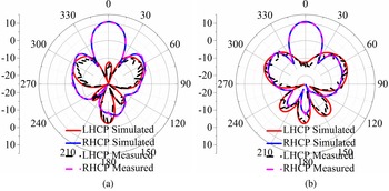
Figure 14 shows plots of radiation patterns at 8.5 GHz in the yoz and xoz planes. The proposed FP antenna achieved good radiation patterns, with cross-polarizations lower than −32 dB and side-lobes lower than −13 dB. These results were validated by real-world measurements with reasonable margins for errors.
Simulated and measured radiation patterns at 8.5 GHz on (a) the xoz plane and (b) the yoz plane

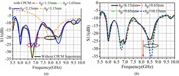
Figure 15 plots reflection coefficients versus frequency with different cavity height hp. Compared with resonate modes without a CPCM superstrate (circled in black), an additional resonance mode (circled in red) was created between 6.5 GHz and 7 GHz when cavity height hp increased to 3.15 mm. Therefore, we conclude that this additional resonance mode was produced by the FP cavity. As depicted in Fig. 15(b), it resonated better at 8.5 GHz by increasing hp from 6.15 mm to 10.15 mm. In conclusion, another resonance mode was also created by the FP cavity at 8.6 GHz. When hp was set to 6.15 mm, both additional resonant modes existed simultaneously. Moreover, the two resonance modes produced by the source antenna shifted to lower frequency bands when CPCM was applied in this design, as seen in Fig. 15(a).
Simulated and measured results for |S11| with different cavity height, hp, (a) different values under 6.15 mm, and (b) different values above 6.15 mm

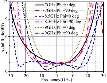
Figure 16 shows a plot of the simulated AR versus the incident angle at 7, 8.5, and 9 GHz. The AR curves were all below 3 dB in the scope of ±15°, and the width of the 3-dB beam was consistent with that of the antenna boresight beam at different frequencies.
Simulated AR versus incident angle at 7, 8.5, and 9 GHz

Table 2 compares the proposed FP antenna to other kinds of FP antennas. Our proposed FP antenna produced circularly-polarized radiation using the checkered PCM and off-center linearly-polarized MPA. Additionally, the proposed FP antenna possessed high gain, wideband operation, circular polarization, and low RCS, giving it a low profile.
Performance of the proposed FP antenna and other kinds of FP antennas

“–” represents null.
Conclusions
We have proposed a novel FP antenna consisting of a checkered PCM, corner-cut square patch antennas, and a sandwiched compound. Checkering the PCM reduces RCS, improves wideband circular polarization, and increases the gain. The corner-cut square patch antennas facilitate high reflectivity, satisfactory transmission magnitude, and the desired phase difference. The sandwich compound is useful in reducing cross-polarization and increasing the gain. Simulation results show that the proposed FP antenna achieves the desired bandwidth and gain improvements. We also subsequently fabricated a prototype with a sequentially rotated feeding network for verification. RCS reduction in the prototype reached −18 dBsm. Measurements from the simulation and prototype were similar, with a reasonable margin of error. A comparison of our proposed FP antenna with its checkered PCM to other kinds of FP antennas shows that our design offers high gain, wideband circular polarization, low cost, low RCS, and a low profile. These features make our proposed antenna appropriate for communication systems due to its superior AR and gain in the C/X band.
Acknowledgements
We thank LetPub (www.letpub.com) for its linguistic assistance during the preparation of this manuscript.
 Qiang Chen was born in Jiangxi, China. He received his master's and Ph.D. degrees from Air Force Engineering University (AFEU), Xi'an, China, in 2015 and 2019, respectively. He is currently a lecturer at Air Force Early Warning Academy, Wuhan, Hubei, China. His research interests include microwave circuits, antennas, and arrays.
 Changhui He was born in 1973. She received the master degree from Central China Normal University. She is currently an associate professor at Air Force Early Warning Institute. She is interested in electromagnetic field, microwave technology, and antenna design. She has published over 20 technical papers and authored one book. She is holding four national invention patents.
 Di Zhang received the B.S., M.S., and Ph.D. degrees from Air Force Engineering University (AFEU), Xi'an, China, in 2013, 2015, and 2019, respectively. He is currently a lecturer with Air Force Early Warning Academy. His research interests include RF orbital angular momentum antennas, reflect array antennas, and metasurface.
 Liang Hong was born in Wuhan, China. He received the B.S. and M.S. degrees from the Huazhong University of Science and Technology, Wuhan, China, in 2005 and 2011, respectively. His research interests include microwave devices and microwave technology.
 Siyu Huang was born in Hunan, China. He received the B.S. and M.S. degrees from Hunan University, Changsha, China and Air Force Engineering University, Xi'an, China, in 2005 and 2011, respectively. His research interests include microwave devices and microwave technology.
 Jiabei Hu is now pursuing the B.S. degree from Hubei University, Wuhan, Huibei, China, in 2017. Her research interests include optical communication systems, EW antennas, and signal processing.
 Zhulin Cui was born in 1995. She received the B.S. degree from Hainan University, Haikou, China, in 2013. She is currently an assistant engineer with the Department of Data Information. Currently she is pursing the master degree from Harbin Engineering University. She is mainly working on the research of network engineering.