1. Introduction
1.1. Design inspiration and anatomical analogy
The human hand, as a vital component of our bodily structure, serves as the primary executor in our daily activities, characterized by its high degree of flexibility and complex functionality. It provides excellent inspiration and reference for the design and development of robotic hands. By emulating the hand’s flexibility, gripping ability, and precision manipulation, robotic hands can better adapt to various work environments and task requirements [Reference Zhu, Wu, Hang, Lin and Sun1].
Traditional rigid robotic hands perform well in tasks requiring positioning accuracy and load capacity, but often lack compliance, risking damage to fragile [Reference Becker, Teeple, Charles, Jung, Baum, Weaver, Mahadevan and Wood2–Reference Tai, El-Sayed, Shahriari, Biglarbegian and Mahmud7]. To address this challenge, some researchers have introduced dampers with elastic components into robotic hands to impart them with a certain level of compliance [Reference Yin, Wang, Zhao, Lou and Shen8]. However, these designs typically result in structural and control complexity [Reference Grebenstein, Chalon, Friedl, Haddadin, Wimböck, Hirzinger and Siegwart9].
Soft robotics has emerged as a promising alternative, leveraging flexible materials and diverse actuation strategies [Reference Bicchi10–Reference Laschi, Mazzolai and Cianchetti11] for safe human interaction [Reference Xie, Domel, An, Green, Gong, Wang, Knubben, Weaver, Bertoldi and Wen12–Reference Xie, Chen, Liu, Yuan, Shao, Yang, Domel, Zhang and Wen14]. Yet challenges persist in stability and load capacity [Reference Wang, Yu, Abrego Serrano and Ahn15–Reference Kellaris, Rothemund, Zeng, Mitchell, Smith, Jayaram and Keplinger23]. Hybrid rigid-soft designs [Reference Yang, Zhang, Kan, Zeng and Wang24–Reference Shintake, Schubert, Rosset, Shea and Floreano26] and fiber-reinforced actuators [Reference Connolly, Walsh and Bertoldi27–Reference Ferrandy, Indrawanto, Ferryanto, Sugiharto, Franco, Garriga-Casanovas, Mahyuddin, Rodriguez y Baena, Mihradi and Virdyawan28] partially address these limitations but face trade-offs in fabrication precision, energy efficiency, and application scope [Reference Hu, Huang, Dong and Sun29–Reference Basumatary and Hazarika34].
Inspired by human finger anatomy, we propose the multi-joint composite finger, based on fabric-enhanced actuation. Human fingers comprise key components such as phalanges, interphalangeal joints, flexor tendons, extensor tendon sheaths, and fingertip pads, which cooperate and work together to confer grasping abilities for everyday activities.
The presence of both phalanges and flexor tendons allows controlled rotational movement around the joints, essential for precise manipulation. Without the presence of flexor tendons and extensor tendon sheaths, fingers would lack controlled rotational motion in space. Similarly, without phalanges, fingers would lack substantial load-bearing capacity during grasping tasks.
Flexor tendons connect the inner phalanges to the muscles, generating tension when muscles contract to produce bending motion for grasping tasks. When muscles relax, flexor tendons facilitate the return of fingers to their original state. Extensor tendon sheaths connect the outer phalanges to the muscles, transmitting the force of extensor muscles to the phalanges, ensuring sufficient strength while maintaining flexibility and coordination.
Tendons offer advantages such as high tensile strength, compact size, and significant energy generation, contributing to the slender and resilient appearance of fingers. Additionally, soft tissues like skin provide sensation and suppleness, allowing fingers to exert appropriate force when gripping objects.
1.2. Novelties and methods
After analyzing and studying the functions of various components of the human finger, the functional replacement structure was designed by integrating a 3D-printed rigid exoskeleton with a fabric-reinforced pneumatic bladder to enable finger adaptation for both daily activities and delicate manipulations. This design synergizes rigid structural integrity (high load capacity) with soft actuator compliance (adaptive deformation), addressing the limitations of existing solutions. Key innovations include:
-
• Fabric-reinforced pneumatic bladders enhancing radial stiffness (240 kPa burst pressure) while maintaining axial compliance.
-
• Hinge-jointed phalanges enabling human-like multi-degree-of-freedom motion.
-
• Coordinated bladder actuation for stable grasping and dexterous manipulation of irregular objects.
Our multi-joint composite finger represents a significant advancement over conventional rigid-soft hybrid manipulators through the integration of three biomimetic innovations: (1) discrete hinge-jointed phalanges facilitate anthropomorphic segmented articulation, enabling effective grasping of irregular objects; (2) anisotropic fabric-reinforced pneumatic actuators simultaneously enhance radial stiffness while maintaining axial compliance for adaptive object envelopment; (3) methodologically, this work combines topology-optimized additive manufacturing with layered fabric reinforcement and coordinated pneumatic actuation, establishing a scalable alternative to traditional tendon-driven mechanisms and homogeneous soft robotic designs.
2. Structural design and actuation principles
2.1. Composite finger architecture
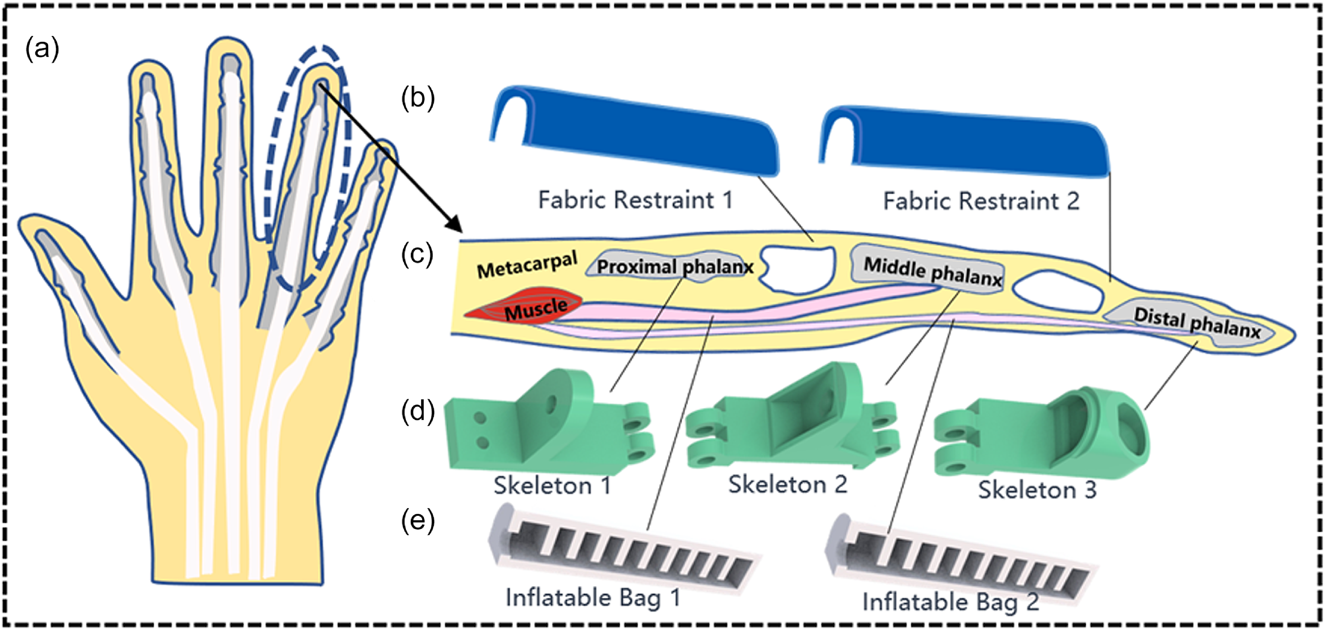
Figure 1(a) depicts a schematic diagram of the human hand structure, while Figure 1(c) shows an anatomical diagram of a human finger. The structure of the finger involves a combination of rigidity and flexibility, including finger bones, muscles, and tendons. The structure of the bionic composite finger, as shown in Figure 1(d), (e), consists of three segments of rigid skeleton and two flexible bladders with fabric reinforcement for actuation. The lengths of the rigid skeletons are 46, 51, and 40 mm, respectively, to better simulate the actual size of human fingers. The rigid skeleton primarily bears the load during object grasping, and all three components are fabricated using 3D printing technology. The commonly used PLA material is selected, with a density of 1.25 g/cm³, a tensile strength of 34 MPa, and a bending strength of 77 MPa, which adequately meets the requirements for daily grasping tasks. As a key component, the performance of the flexible driving bladder directly influences the response speed and load-bearing capacity of the bionic finger. It is fabricated using silicone casting technology, with the selected materials consisting of two components, Agent A and Agent B, mixed in a 1:1 ratio. The key material parameters were measured as follows: a tensile strength of 5.2 MPa, a viscosity of 6000 mPa s, a Shore A hardness of 25, a tear strength of 20 kN/m, and an elongation at break of 450%. The resulting mixture has a vulcanization time of 3–5 hours at room temperature, ensuring that its performance meets the design requirements. The silicone air chamber was reinforced with plain-woven fabric constraints, the fabric exhibited anisotropic mechanical behavior: under axial tension, it permitted large deformations with elastic recovery, while remaining strain-resistant in the radial direction. The three adjacent rigid phalanges are connected by a joint hinge, which ensures both the structural strength of the finger and that the finger joints can rotate freely in space along the bending direction, but reverse rotation will result in a limited rotation angle due to the constraint of the driving bladder.
Finger anatomy illustration and structural design. (a) Schematic diagram of the human hand structure. (b) Fabric constraints. (c) Schematic diagram of the rigid-flexible coupling structure of the human hand. (d) Finger rigid skeleton structure. (e) Driving.

The working principle of fabric-reinforced actuated flexible bladders is mainly based on the axial deformation of the silicone material that occurs during inflation, generating a thrust force that drives the rigid joints to rotate. Specifically, one end of the driving bladder is fixed in the groove of the rigid skeleton using silicone adhesive, while the other end’s air passage passes through the air passage hole of the rigid skeleton. To limit the large radial deformation of the bladder, a fabric constraining layer is used instead of the extensor tendon sheath in human fingers to constrain the bladder. This design aims to improve the finger’s load-bearing capacity.
In order to enhance the grasping effectiveness of the bionic composite finger, we have incorporated grooves at the fingertip and finger pad positions of the rigid finger bones, designed for mounting silicone pads with corrugated grooves. The purpose of this design is to ensure that the composite finger does not damage objects during grasping while also increasing friction with the object’s surface to improve grip stability.
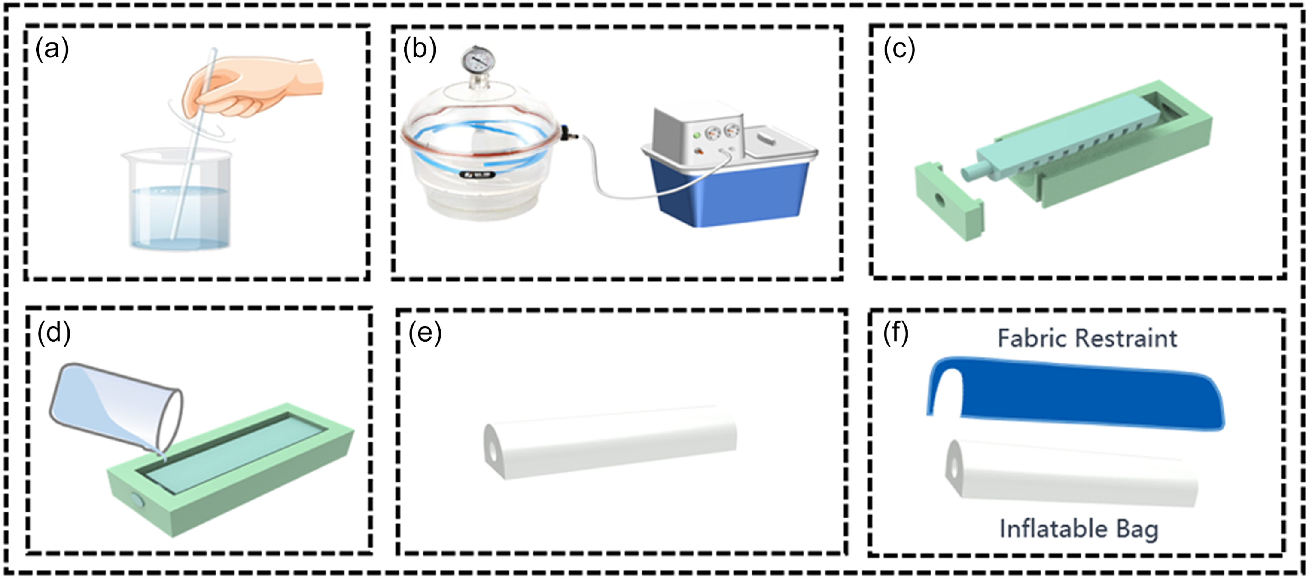
Through this approach, a synergistic interaction is established between the rigid skeleton and the driving bladder, enabling the finger to be both flexible and controllable while performing various grasping tasks. The manufacturing process of the driving bladder is illustrated in Figure 2.
Manufacturing process of drive bladder. (a) Mixing of two-component silicone rubber. (b) Vacuum deaeration treatment. (c) Mold assembly (d) Silicone rubber pouring. (e) Demolding. (f) Fabric-reinforced bladder.

2.2. Grasping gestures of human fingers
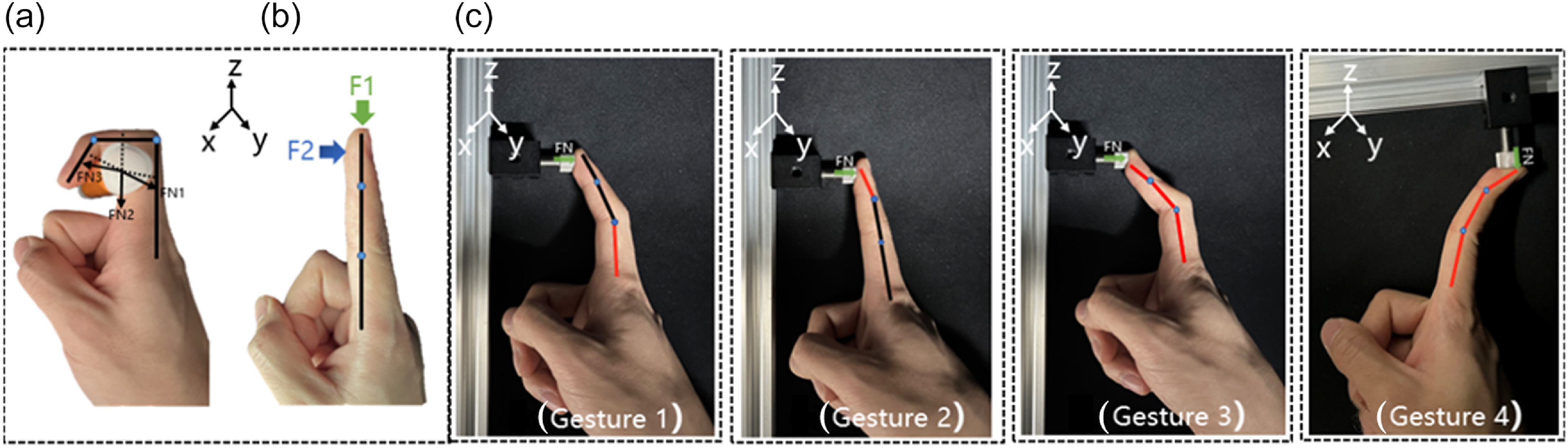
The human hand can not only achieve active enveloping gestures (Figure 3(a)), but also maintain a relatively stable relationship between several phalanges of the fingers under the action of forces from different directions (Figure 3(b)). The relationship between these phalangeal bones provides a high degree of compliance without sacrificing the finger’s force output, allowing the finger to flexibly switch between grasping gestures according to different grasping tasks.
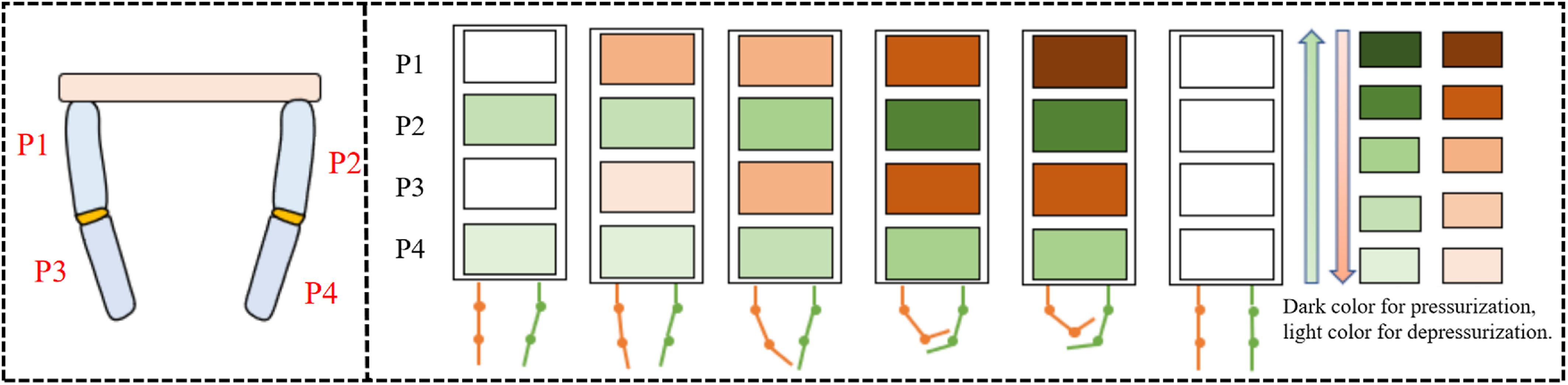
(a) Envelope mode of the fingers. (b) Force situation on the fingers. (c) Driving gestures (Gesture 1–4).

In order to mimic the various gestures of human fingers during grasping tasks, we designed a three-segment rigid skeleton connected by hinges to enable flexible movement in space, simulating the diverse functionalities of fingers. The flexible driving bladders are fixed to the rigid skeleton’s grooves and through-holes by adhesive bonding. The driving force generated by the bladder actuation is transmitted among the three rigid segments, allowing the distal phalanges to form four pressing gestures at the fingertip: light, moderate, firm, and excessive, as shown in Figure 3 (Gesture 1–4). Gesture 4 is a mechanism of over-travel lock caused by one of the bladders being pressurized while the target object is too heavy. Therefore, when performing grasping tasks, it is necessary to adjust the air pressure of the two bladders appropriately according to the size and weight of the object, enabling the three phalanges to cooperate with each other to complete the grasping task.
2.3. Actuation mechanics
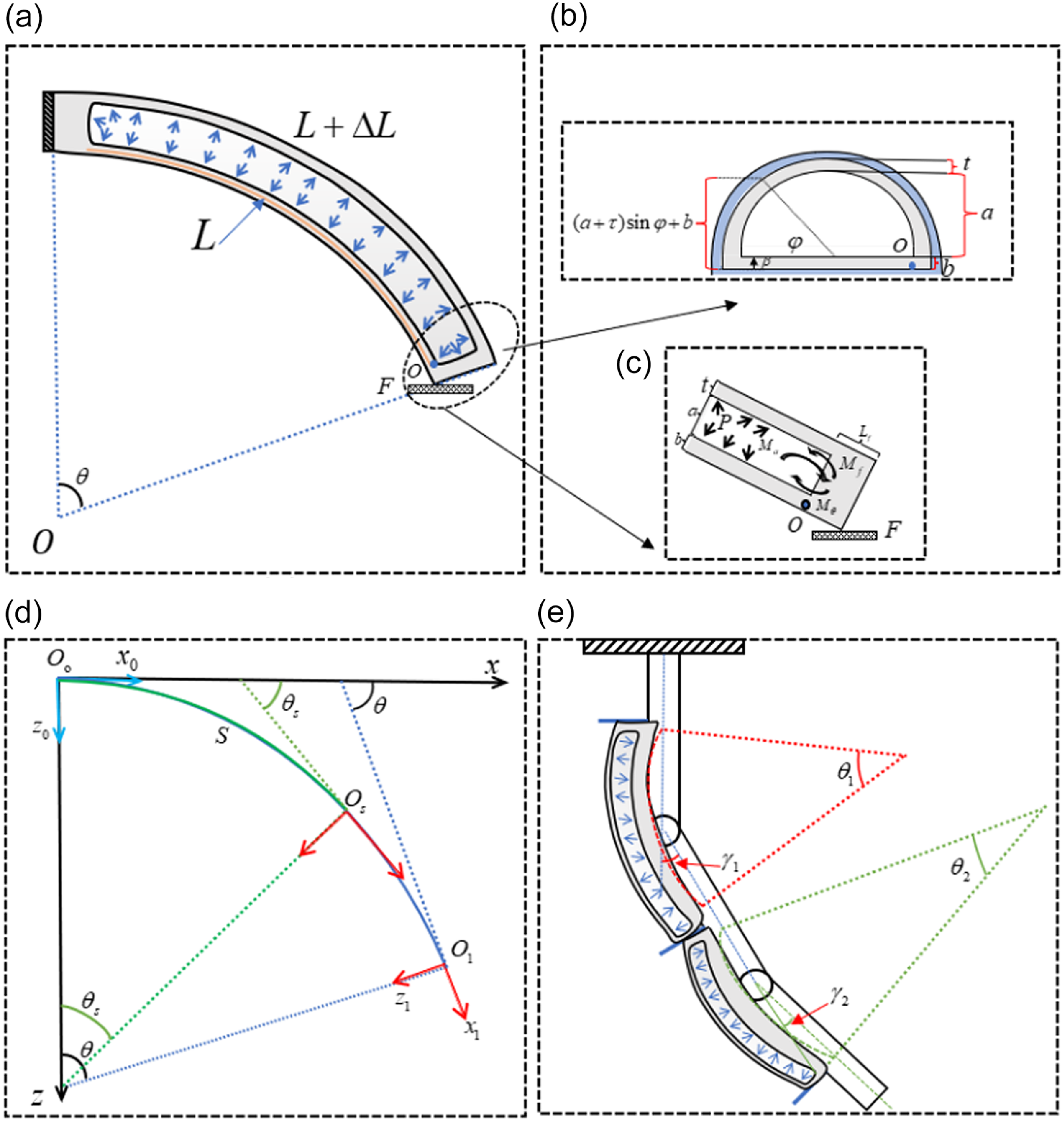
The two enhanced flexible driving bladders of the composite finger have the capability of independent driving and cooperative driving. These two flexible driving bladders are tightly bonded to the rigid skeleton, serving as both active driving components of the rigid skeleton and compliant driving components. During active driving, the proximal bladder inflates and expands, driving the rigid joints to rotate. At this time, the distal joints are not driven, and continuing to increase the air pressure of the proximal joints will cause the rigid skeleton to transmit force, thereby driving the distal joints to produce compliant driving. The deformation mechanism of the driving bladder is illustrated in Figure 4.
Composite finger driving principle composite finger driving principle. (a) Side view of the bladder in bending state. (b) Cross-sectional view. (c) Distal view of the torque generated by the bladder. (d) Position schematic. (e) Geometric relationship.

Due to the anisotropy of the driving bladder rubber material, the model of the entire bladder is simplified. Based on the segmented constant curvature assumption, it is assumed that the curvature of each part remains the same during motion. The fabric reinforced pneumatic bladder is modeled as an incompressible Neo–Hookean hyperelastic material [Reference Zhang, Zhang, Yang and Pu32]. Its strain energy density function is defined as follows:
 \begin{equation} \textit{W}=\frac{\mu }{2}\left(I_{1}-3\right) \end{equation}
Here,
 $\mu$
represents the initial shear modulus of the material, and
 $I_{1}$
is the first invariant of the principal stretches
 $\lambda _{1} , \lambda _{2} , \lambda _{3}$
along three directions.
 \begin{equation} I_{1}={\lambda _{1}}^{2}+{\lambda _{2}}^{2}+{\lambda _{3}}^{2} \end{equation}
The principal stress
 $\textit{s}_{i}$
can be represented as:
 \begin{equation} \textit{s}_{i}=\frac{\partial W}{\partial \lambda _{i}}-\frac{p}{\lambda _{i}} \end{equation}
The large deformation of the silica gel material is fully taken into account during the entire deformation process of the bladder. The introduction of compressed air into the bladder will cause the bending deformation of the driving bladder.
 $\lambda _{1}$
is the main stretching of the driving bladder along the axial direction, and the strain in the circumferential direction can be ignored. Doesn’t count, so
 $\lambda _{2}=1$
. Finally, considering the incompressibility of the material,
 $\lambda _{1}\lambda _{2}\lambda _{3}=1$
is obtained.
 \begin{equation} \lambda _{1}=\lambda ,\quad \lambda _{2}=1,\quad \lambda _{3}=\frac{1}{\lambda } \end{equation}
Assuming that the radial stress
 $s_{3}=0$
in the thickness direction of the driving bladder, combining Eqs. (1)–(3) can be obtained:
 \begin{align}s_{1} & =\displaystyle\frac{\partial W}{\partial \lambda _{1}}-\displaystyle\frac{P}{\lambda _{1}}=\mu\, \left(\lambda -\displaystyle\frac{1}{\lambda ^{3}} \right) \nonumber\\[4pt] s_{2} & =\displaystyle\frac{\partial W}{\partial \lambda _{2}}-\displaystyle\frac{P}{\lambda _{2}}=\mu\, \left(1-\displaystyle\frac{1}{\lambda ^{2}}\right) \nonumber\\[4pt] s_{3} & =\mu \lambda _{3}-\displaystyle\frac{P}{\lambda _{3}}=0 \nonumber\\[4pt] p & =\mu {\lambda _{3}}^{2}=\displaystyle\frac{\mu }{{\lambda _{2}}^{2}} \end{align}
In this application, the range of tensile stress (
 $1\leq \lambda \leq 1\textit{.}5$
) is considered. The circumferential stress
 $s_{2}$
is much smaller than
 $s_{1}$
Therefore,
 $s_{1}$
is regarded as the only non-zero principal stress, denoted as
 $s$
below. During the working process, the driving bladder achieves torque balance around the pivot point
 $\textit{o}$
, as shown in Figure 4(c).
 \begin{equation} M_{a}=M_{\theta } \end{equation}
In the above equation,
 $M_{a}$
represents the bending torque generated by the internal pressure of the driving bladder acting on its two ends, and
 $M_{\theta }$
represents the combined torque of the top and bottom layers of the driving bladder,
 $M_{a}$
can be calculated as:
 \begin{equation} M_{a}=2\left(P_{1}-P_{a}\right)\int _{0}^{\frac{\pi }{2}}\left(a\sin \varphi +b\right)a^{2}\cos ^{2}\varphi d\varphi =\frac{4a^{3}+3\pi a^{2}b}{6}\left(P_{1}-P_{a}\right) \end{equation}
 $M_{\theta }$
can be calculated as:
 \begin{equation} M_{\theta }=\int _{\textit{0}}^{b}s\beta \cdot {\textit{2}} (a+t)L\beta d\beta +{\textit{2}}\int _{\textit{0}}^{t}\left(\int _{\textit{0}}^{\frac{\pi }{\textit{2}}}s\tau, \varphi ((a+\tau )^{\textit{2}}{\sin} \varphi +b(a+\tau ))Ld\varphi \right)d\tau \end{equation}
The longitudinal tensile stress and strain of the bottom layer are respectively:
 \begin{equation} \lambda _{\beta }=\frac{R+\beta }{R}=\frac{L/\theta +\beta }{L/\theta }=\frac{\beta \theta }{L}+1 \end{equation}
 \begin{equation} s_{\beta }=\mu \left(\lambda \beta -\frac{1}{\lambda \beta ^{3}}\right) \end{equation}
The longitudinal tensile stress and strain of the top layer are respectively:
 \begin{equation} \lambda _{\tau ,\varphi }=\frac{R+b+\sin \varphi \left(a+\tau \right)}{R} \end{equation}
 \begin{equation} s_{\tau ,\varphi }=\mu \left(\lambda _{\tau ,\varphi }-\frac{1}{{\lambda ^{3}}_{\tau ,\varphi }}\right) \end{equation}
Substituting Eqs. (7) and (8) into Eq. (6) yields the relationship between input pressure and bending angle. Due to the intractability of the integral in the equation, numerical methods must be employed to obtain a solution:
 \begin{equation} P=\frac{6M_{\theta }}{4a^{3}+3\pi a^{2}b} \end{equation}
The deformation bending angle after driving a single driving bladder is
 $\theta$
. Based on the geometric relationship shown in the Figure 4(e), the rotation angle of the composite finger joint can be calculated as:
 \begin{equation} \gamma =\arcsin \frac{R\sin \theta }{L} \end{equation}
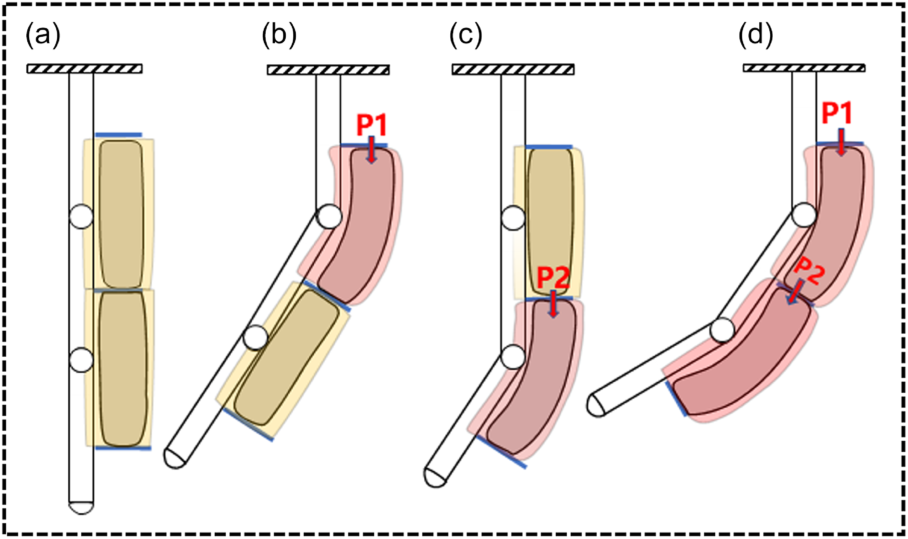
To accommodate different application scenarios, we have designed three driving modes as shown in Figure 5:
Driving modes.

-
1. When the finger needs to grasp fragile and lightweight objects, the proximal driving bladder dominates (Figure 5(b)), transmitting force to the distal joint to grasp the object.
-
2. When the finger needs to grasp small-volume and lightweight objects, the distal driving bladder dominates (Figure 5(c)), adjusting the finger posture by driving the distal joint to grasp the object.
-
3. A single driving bladder has good compliance, but the entire finger may struggle to generate enough force to lift an object. Therefore, two driving bladders can cooperate with each other (Figure 5(d)). Initially, the proximal driving bladder is driven to make contact with the object, then the distal bladder is driven to provide sufficient grasping force to lift the object.
3. Results and discussion
3.1. Bladder performance
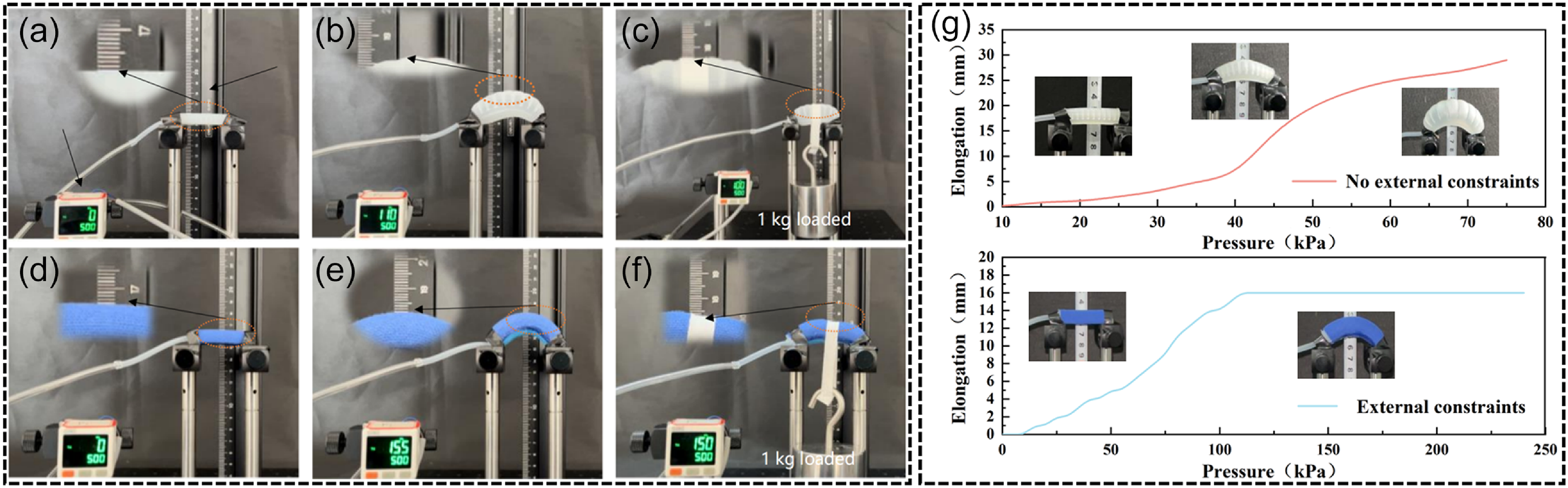
The basic principle of fabric-reinforced driving relies on the different mechanical responses of fabric and rubber materials under tension. This characteristic of the two materials is applied in the design of driving bladders. Simply put, the fabric’s low strain in the radial direction can constrain the radial expansion of the flexible bladder, preventing over-expansion, while allowing deformation and force transmission in the axial direction during actual driving. Figure 6(a–f) illustrates the states of the two types of driving bladders after pressurization. In the experiment, we observed different behaviors of the two types of bladders. Firstly, the bladder without fabric reinforcement continuously expands as the pressure increases, reaching the critical pressure of the bladder at 110 kPa, beyond which further pressure increase would lead to bladder rupture. In contrast, the fabric-reinforced driving bladder gradually reaches saturation after low-pressure inflation. As pressure is applied, the external fabric constraint plays a critical role in increasing the structural stiffness of the driving bladder, preventing significant structural deformation and thus enhancing the bladder’s load-bearing capacity. This design makes fabric-reinforced bladders more stable and controllable compared to those without fabric reinforcement. According to the experimental data shown in Figure 6(g), the critical pressure for the explosion of the fabric-reinforced bladder is 2.181 times that of the bladder without fabric reinforcement. From the saturation pressure value of 110 kPa to the explosion pressure value of 240 kPa, the internal pressure of the bladder increased by 2.18 times, while the external deformation remained almost unchanged. This indicates that the external fabric constraint can convert the internal pressure of the bladder into structural stiffness, demonstrating its strong load-bearing capacity.
Relationship between pressure and expansion degree of two driving bladders. (a) Conventional bladders without pressurization. (b) Conventional bladders at critical pressure. (c) Conventional bladders under 1 kg load. (d) Fabric-reinforced bladders without pressurization. (e) Fabric-reinforced bladders at critical pressure. (f) Fabric-reinforced bladders under 1 kg load.

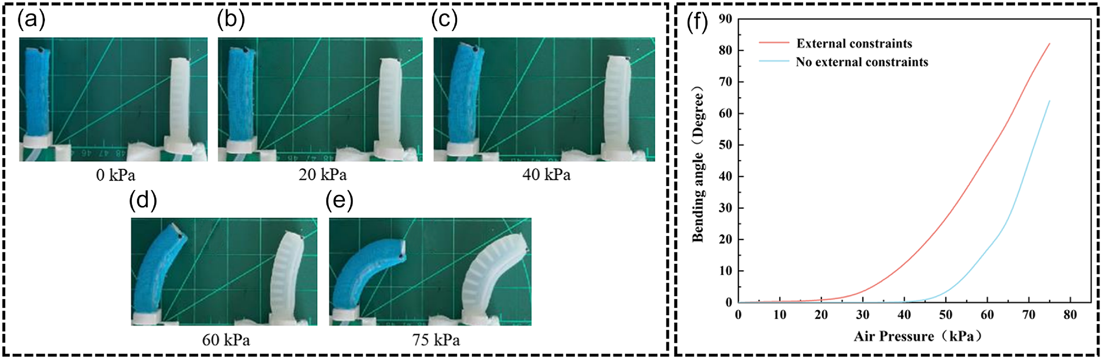
At 150 kPa pressure (Figure 6(f)), the bladder demonstrates remarkable performance, effortlessly bearing a 1 kg weight with only a 3 mm deformation. This clearly proves the outstanding load-bearing capacity of the fabric-reinforced driving bladder. The bending performance is also a key indicator of the bladder’s capabilities. As shown in Figure 7(a–e), the bending states of the two types of driving bladders under the same pressure are compared. The experiments indicate that the bending angles of both types of driving bladders increase with increasing pressure. Under 20 kPa pressure, the externally constrained driving bladder begins to exhibit slight deformation, while the unconstrained driving bladder shows slight deformation only at 45 kPa. Due to insufficient pressure applied to the driving bladder at lower pressures, deformation has not yet been induced. The experimental results in Figure 7(f) demonstrate that, under the same pressure conditions, the fabric-reinforced driving bladder achieves a bending angle of 82.2° at 75 kPa pressure, demonstrating excellent bending performance.
Relationship between pressure and bending angle of two types of driving bladders.

3.2. Joint stability and recovery
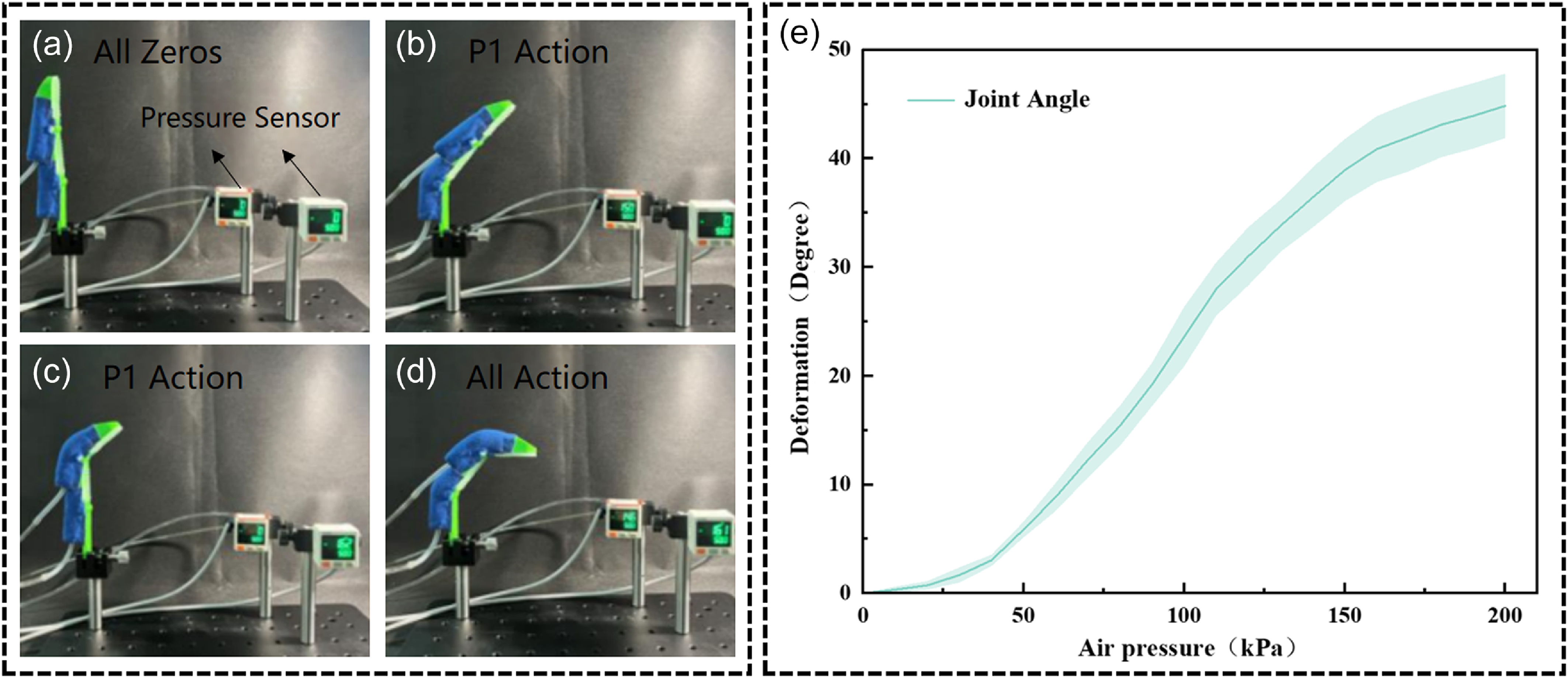
The movement of each joint in the composite finger is controlled by adjusting the pressure of individual bladder. To investigate the influence of the bladder inflation state on the finger’s bending angle, a series of experiments was conducted. Due to assembly errors and the limitations of open-loop control, precise regulation of the pump’s gas supply was unachievable. Consequently, multiple trials were performed to enable statistical analysis of the collected data. During the experiments, the composite finger was securely fixed in a fixture, and varying pressures were sequentially applied to the driving bladder. The joint rotation of the composite finger during inflation was examined, and its motion was recorded in real time using a smartphone camera. Subsequently, the video analysis and modeling software Tracker was utilized to extract the joint rotation angles.
In the experiment, various hand gestures were simulated by changing the pressure of the bladders multiple times, as shown in Figure 8(a–d). When the driving air pressure was 200 kPa, the joint rotation angle reached 44.83°. Here, the pressure applied to the first bladder is denoted as
 $\textrm{P1}$
, and the pressure applied to the second bladder is denoted as
 $\textrm{P}2$
.
Composite finger-driven gestures and joint bending angles.

To assess the rigidity and stability of the composite finger, its performance was tested under the recording of a smartphone camera. Due to the effective damping of impact forces by bladder and fabric constraints in composite finger structures, as well as the rapid attenuation of impact amplitude through rigid skeleton connections, the experimental scenarios included sudden impact tests on unloaded composite fingers and assessments of the stiffness and stability of composite material fingers.
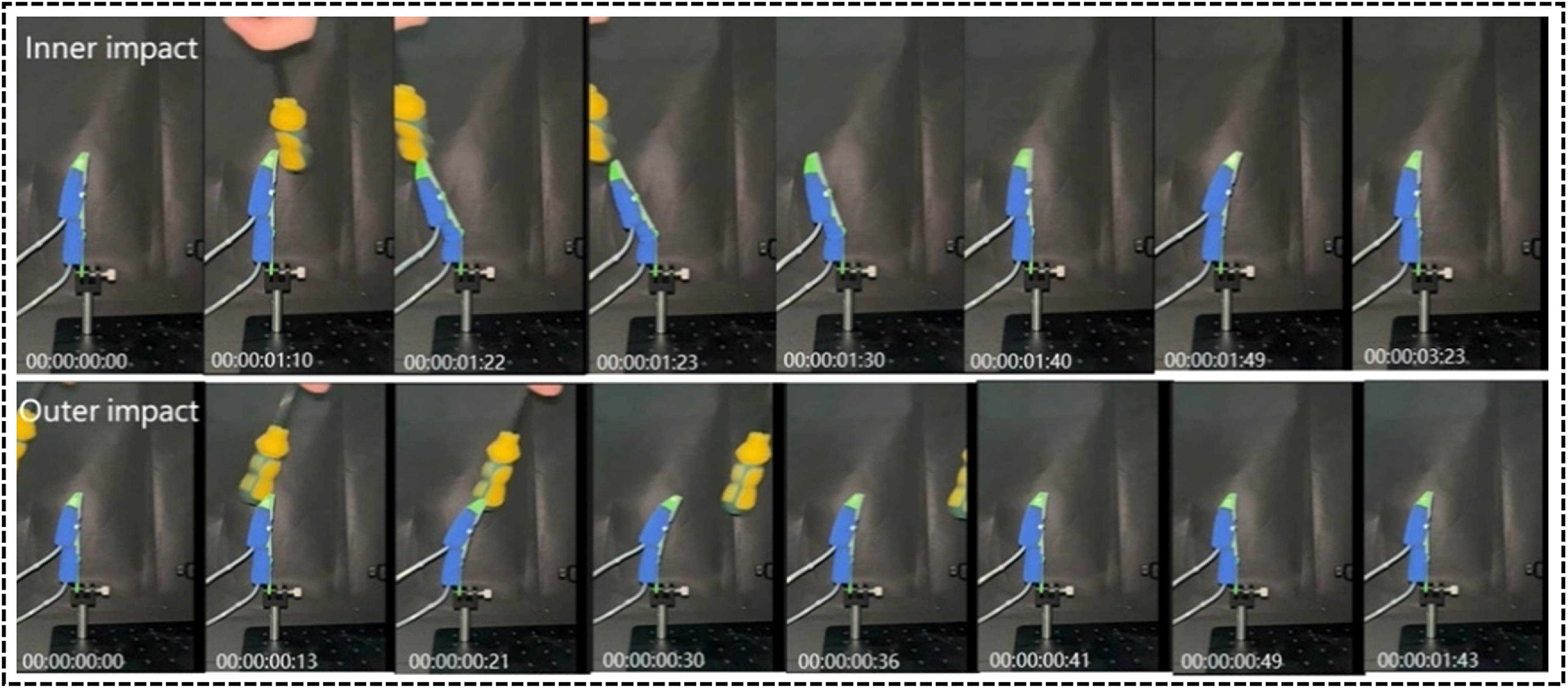
In the experiment, we first used heavy objects to perform a sudden impact test on the finger pulp and back of the finger under no load from both sides of the finger. The results showed that regardless of the direction of the sudden impact, the composite finger was able to return to its initial position in an extremely short time. The process of sudden impact and recovery from both the inner and outer sides of the finger is shown in Figure 9. According to the images recorded by the smartphone camera, when the composite finger was suddenly impacted from the inner fingertip position, the driving bladder near the joint developed folds. This occurred because the distance from the force application point to the proximal joint pivot was relatively large, making it prone to energy concentration at the proximal driving bladder. After the impact was eliminated, the elastic properties of the silicone material facilitated the restoration of the finger joint to its initial state. As shown in Figure 9, the time taken for the finger to return to its original state after being impacted from the inner and outer sides was 2 and 1.22 s, respectively.
No-load finger inner and outer impact and recovery process.

In addition, there were no noticeable instances of back-and-forth oscillation during the testing of the composite finger. This characteristic can be attributed to the static friction between the fabric constraints, the material properties of the flexible bladders, and the rigid joint fixtures. The combined effect of these factors effectively mitigated any unnecessary vibrations during finger movement, ensuring stability and precision.
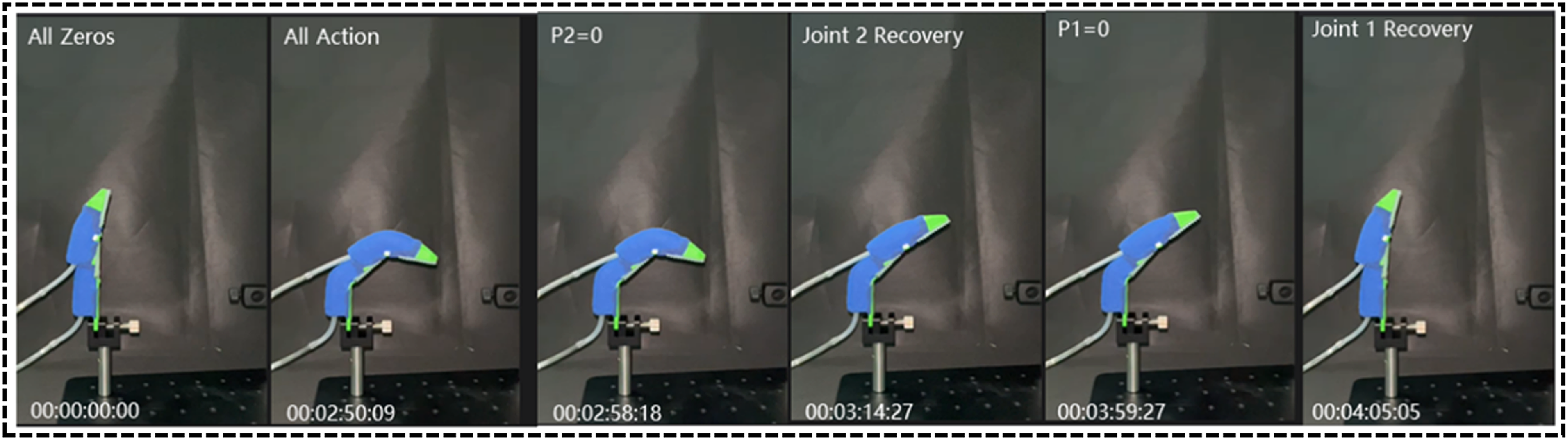
After completing the grasping task, the recovery speed of the fingers during the unloading process is also an important indicator of finger performance. In this section of the experiment, the two driving bladders of the composite finger were slowly pressurized to 160 kPa. During this process, the fingers’ joints could be observed rotating slowly to the maximum rotation angle. The morphology of the composite finger during unloading is shown in Figure 10. Similarly, the entire process of finger recovery was recorded using a mobile phone camera. As the flexible driving bladders inflated, they pushed the rigid joints to rotate. Upon unloading, the silicone material contracted back to its initial state, thereby returning the finger joints to their original position. According to the images recorded by the mobile phone camera, the joints of the composite finger were able to recover to their initial position in about 0.5 s after unloading.
Joint recovery process after finger unloading.

The aforementioned experiment demonstrates that composite fingers can rapidly adapt to and recover from impacts or external disturbances, returning to normal working conditions. This finding confirms their exceptional stability and rapid recovery capabilities when performing various tasks.
3.3. Force output
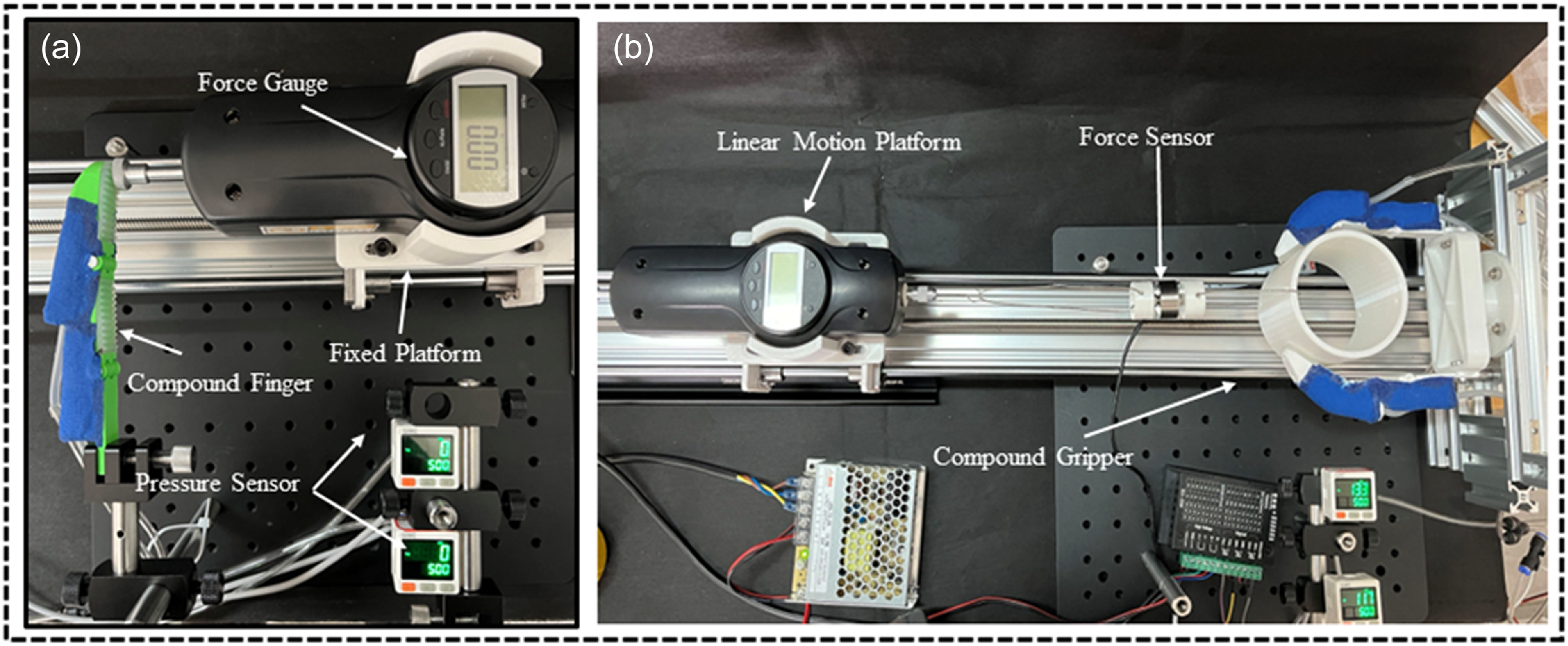
To test the maximum pressure produced at the fingertip position of a single composite finger under different driving pressures, the finger was secured on a fixture as shown in Figure 11(a), ensuring contact between the fingertip and the force sensor test point on the linear motion platform. Initially, the pressure in both driving bladders of the finger was set to 0 kPa. Subsequently, positive pressure was sequentially applied to the distal and proximal driving bladders using a miniature air pump, with intervals of 10 kPa, and the changes in pressure readings of the force sensor at the fingertip test point were recorded throughout this process.
Finger output force testing device. (a) Experimental setup for measuring maximum pressure output of a single bio-inspired finger under varying actuation pressures. (b) Experimental setup for tensile force testing of a two-finger gripper.

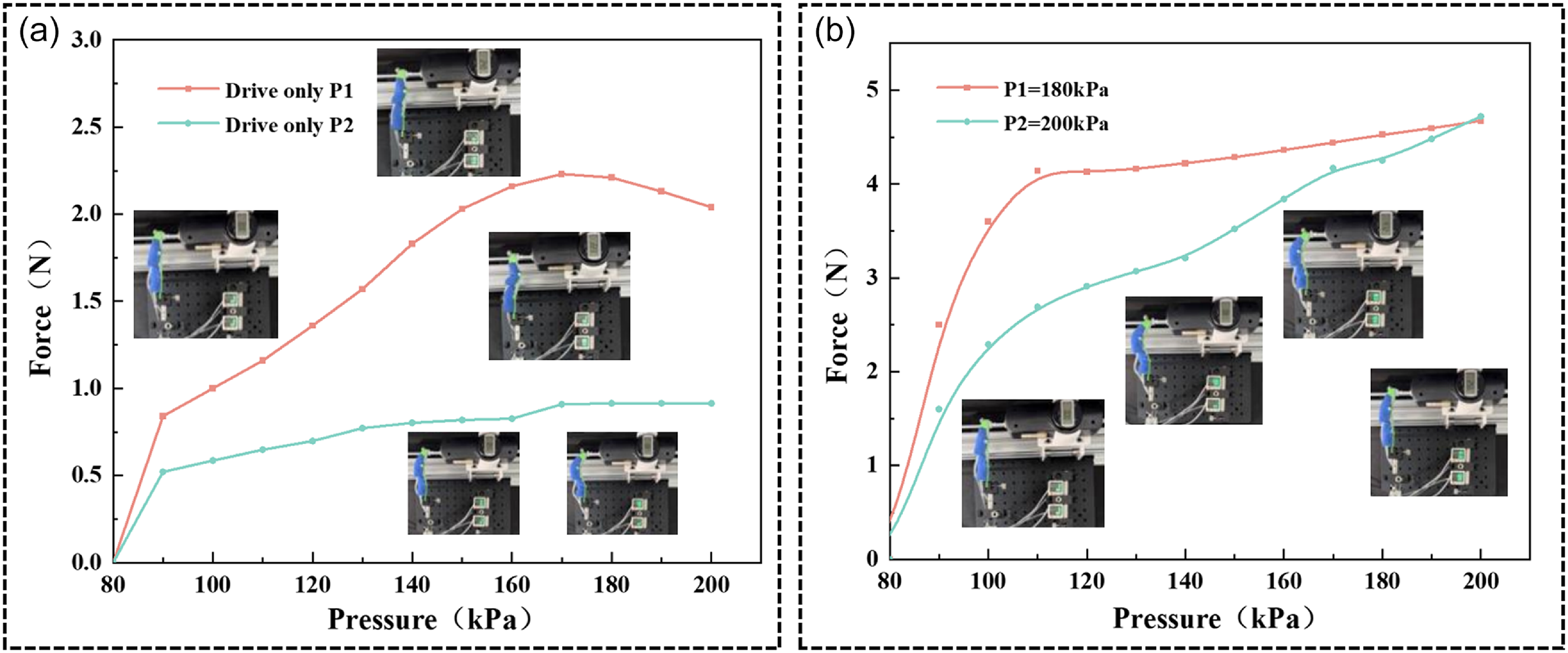
Based on the real working principle of the human hand, we first tested the magnitude of fingertip output force during Gesture 1 using the experimental setup described above. During the experiment, we continuously supplied stable positive pressure to the driving bladder P1, while maintaining the pressure in P2 at 0 kPa. The pressure in the bladders was monitored in real-time using a pressure sensor. The pressure readings at the fingertip contact point were recorded via camera during the driving process. When the pressure was below 80 kPa, the force sensor reading remained at 0 N. This was due to the friction between the rigid skeleton joints, preventing the thrust generated by the driving bladder from rotating the joints. When the pressure increased to 100 kPa, the force sensor displayed a reading of 0.85 N. As the pressure continued to increase, the force sensor reading also increased. As shown in Figure 12(a), when the pressure reached 170 kPa, the force sensor reading peaked at 2.23 N. However, as the pressure further increased, the force sensor reading began to decrease. This was because the driving bladder at the distal end of the composite finger exceeded its compliance capacity as the joint angle increased, leading to a reduction in the contact force at the fingertip. This phenomenon is similar to adverse physiological effects that may occur in the human hand during actual movement when joints or bones are subjected to pressures or loads beyond their tolerance range, such as soft tissue damage, fractures, dislocations, etc.
The relationship between input air pressure and finger output force. (a) Experimental comparison of Gesture 1 and Gesture 2. (b) Performance evaluation of Gesture 3.

In the experiment for Gesture 2, we employed the same method as Gesture 1. Continuous positive pressure was supplied to the driving bladder P2 while maintaining the pressure in P1 at 0 kPa. Similar conclusions to those obtained during the Gesture 1 testing process were derived from the experimental data. When the pressure was below 90 kPa, the force sensor reading remained at 0 N. When the pressure reached 180 kPa, the force sensor reading peaked at 0.91 N, and further increasing the pressure did not change the force sensor reading.
In the testing experiment for Gesture 3, the bladder P1 was first driven until it reached the maximum pressure of 180 kPa, and then P1 was maintained at this pressure while P2 was driven to 200 kPa. The pressure at the fingertip increased with the increase in pressure in both driving bladders until it reached a stable state. As shown in Figure 12(b), the force sensor recorded a peak reading of 4.77 N at the final pressure of 200 kPa.
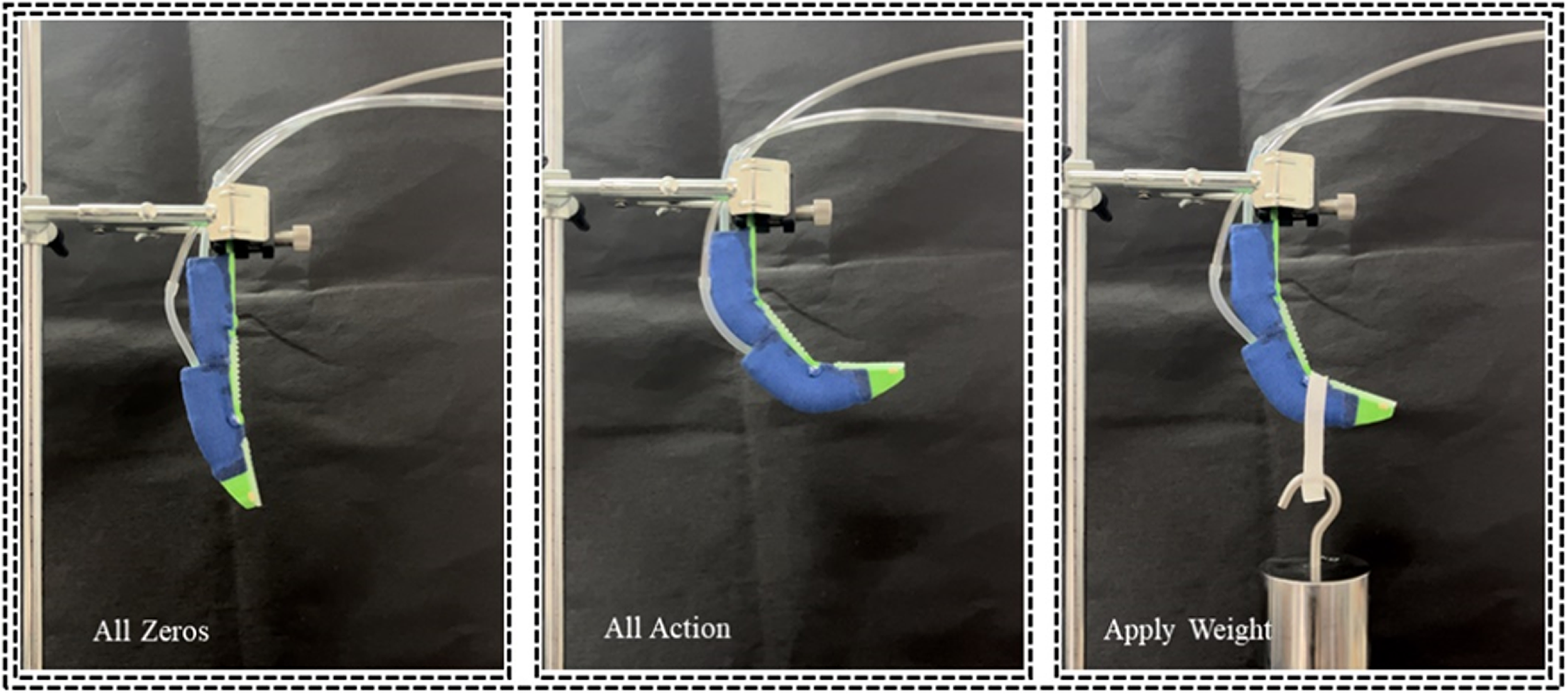
Additional experiments characterized the finger’s heavy-object grasping stability. Figure 13 illustrates that the composite finger can stably grasp 1 kg weight under the driving action.
Composite fingers stably pick up heavy objects.

The experiments above demonstrate that the composite fingers we designed and manufactured possess the flexibility of independent joint movement, and the two joints can cooperate with each other effectively to grasp heavy loads.
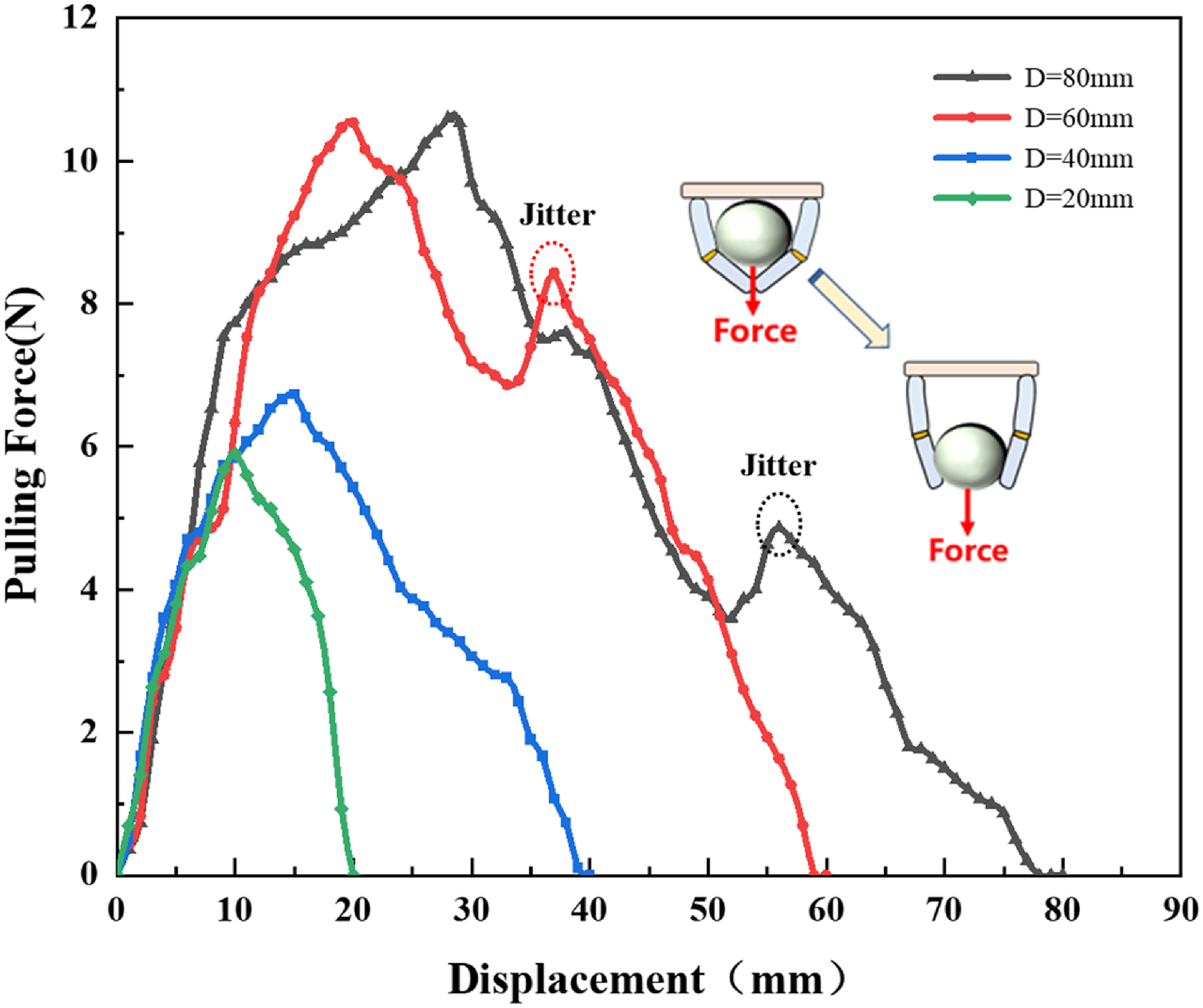
To better quantify the actual performance of the composite fingers, we assembled two composite fingers into a claw and conducted a tension test. In the experiment, the claw securely grasped a cylindrical tube manufactured using 3D printing. A steel wire rope passed through the cylinder, with one end connected to a linear moving platform equipped with a force sensor (as shown in Figure 11(b)). The platform moved slowly until the cylinder was completely released from the claw, constituting one valid experiment. The peak force recorded during the entire experiment process was considered the maximum grasping force of the claw.
According to the experimental data in Figure 14, we observed that as the linear moving platform moved, the cylindrical tube was gradually pulled out from the envelope of the claw. With the increase in displacement, the tension continuously rose to reach the peak value of each experiment and then gradually decreased until the object was pulled out of the claw.
Displacement and peak force magnitude.

When grasping objects with diameters similar to the palm, such as cylinders with diameters of 80 mm and 60 mm, during the process of decreasing tension after reaching the peak force of each experiment, slight shaking may occur. Due to the gradual transition of the claw’s grasping gesture – from mutual enveloping between the two finger joints to pressing by the far-end joint – the interaction between the claw and the enveloped object becomes less smooth and uniform. This uneven force transmission may lead to slight shaking.
3.4. Grasping performance
To comprehensively demonstrate the grasping performance of the composite fingers, we conducted a series of grasping experiments to evaluate the gripping performance of the gripper. Each grasping experiment consisted of three steps: picking up, holding, and releasing, ensuring that each experiment had at least a few seconds of stable holding time.
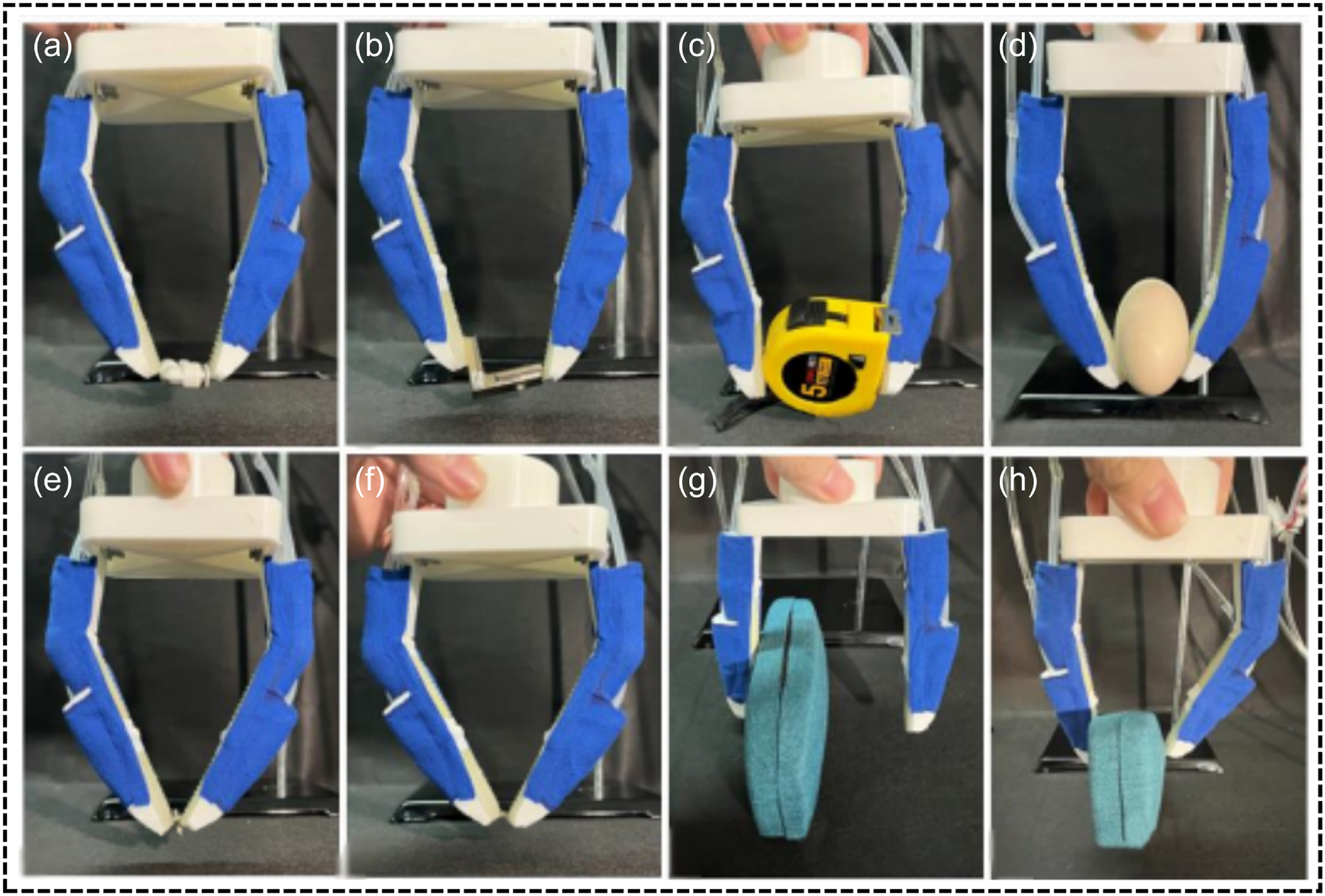
By flexibly driving the proximal and distal phalange joints of the composite fingers separately, we successfully and securely grasped objects that were much smaller than the gripper using Gesture 1 and Gesture 2, such as pneumatic couplings (Figure 15(a)) and small screws (Figure 15(e), (f)). High compliance is another important feature of our composite fingers. Due to their unique structure and material properties, the joints of the composite fingers exhibit extremely high compliance. Specifically, when the fingers grasp some objects with a larger width, they first rely on the proximal joint bladder to drive the distal phalanx to rotate. The fingers approach the object in the form of gesture 1, and then drive the proximal bladder to make the compound Fingers adapt to the shape of the object to grasp the object stably (Figure 15(c)). In addition to grasping small and wide objects, the fingers can stably grasp fragile objects such as eggs (Figure 15(d)) and maintain a stable grip for a period of time.
The gripper grabs a series of irregular objects.

Furthermore, the highly compliant and flexible characteristics are also demonstrated when handling offset objects. When it is necessary to grasp objects with an offset from the center of the gripper (Figure 15(g–h)), the composite fingers can deform adaptively to the appropriate position and then perform the grasping task. For example, one finger adopts Gesture 1 while the other adopts Gesture 2, and both fingers securely pinch and grasp the object. When grasping objects that are relatively light but have a certain offset, the composite fingers can first push the object to the center of the gripper and then grasp it to achieve the grasping task.
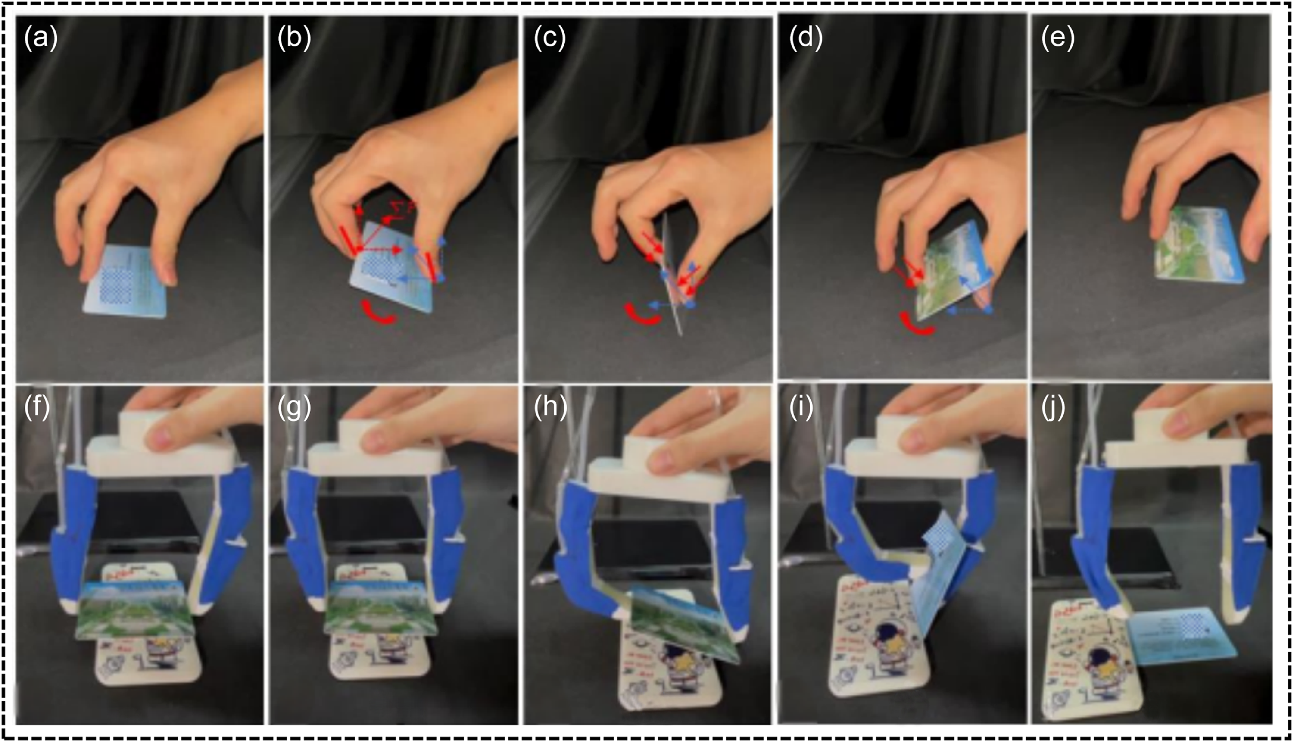
In addition, the composite fingers can also achieve a strategy similar to the human hand in stably grasping thin objects and flipping them (Figure 16(a–e)). The five key stages for the human hand to flip objects are: first, the position of the thin object is located through the vision system; then, the fingers need to adjust the position and spacing appropriately to contact the target object and grasp it; then, after adjusting the position, lift In the rotation stage, the contact point of one finger is used as the fulcrum, and the proximal joint of the other finger is first rotated, so that the thin object rotates around the side where the fulcrum is located as the rotation axis until one side of the thin object leaves the table; then the flipping stage continues, and the far side The end joint rotates cooperatively with another finger to ensure that the thin object flips smoothly; finally, after completing the flipping task, the finger needs to adjust its position appropriately to place the flipped thin object at the target position.
Finger flip strategy.

In the strategy of using human hand-like movements to flip objects, by applying differential pneumatic pressures to the joint bladder of the composite fingers, the gripper generated adaptive grasping postures (Figure 17), enabling stable grasping and flipping of delicate objects, thereby mimicking human-like dexterous manipulation, as shown in Figure 16(f–j). Through this experiment, we clearly observed that applying appropriate pressures to multiple pneumatic actuators enables the composite fingers to achieve excellent performance in complex tasks, especially in stable grasping and flipping operations that mimic human hand-like actions.
Multi-bladder coordination.

These experiments demonstrate that the designed composite finger not only generates sufficient output force for grasping small objects in daily life, enabling tasks such as grasping and flipping, but also exhibits excellent bladder performance and joint stability recovery capabilities. These advantages further expand the potential applications of the gripper.
4. Conclusion
This study presents a bioinspired rigid-soft composite finger that bridges the gap between compliance and load capacity. Key contributions include:
Enhanced durability: Fabric reinforcement increased burst pressure by 2.18×.
Human-like dexterity: Coordinated bladder actuation enabled multi-modal grasping and flipping.
Rapid recovery: <2 s post-impact stabilization.
Future work will optimize control algorithms for dynamic environments and explore scalable manufacturing. This design holds significant potential for industrial automation, assistive robotics, and delicate object manipulation.
Author contributions
Junqing Yin contributed key ideas to the article, was responsible for designing and drafting the manuscript, and provided guidance throughout the research; Jinlong Li was responsible for fabricating the bionic composite finger and conducting experiments; Siqi Niu assisted in the development of the control system associated with the experiment; Qingqing Xu processed experimental data, and checked the content of the article. All authors contributed valuable feedback and participated in the revision process.
Financial support
This research was supported by the Open Fund of Jiangsu Engineering Research Center of Key Technology for Intelligent Manufacturing Equipment.
Competing interests
The authors declare no conflict of interest.
Ethical approval
Not applicable.
Data availability statement
All data that support the findings of this study are included within the article (and any supplementary files).