
I. INTRODUCTION
Extensive grain refinement of metallic structures by severe plastic deformation (SPD) yields an enormous enhancement of the strength of materials. This improvement of the mechanical properties is also reflected in the high cycle fatigue (HCF) performance, making this material class ideal for frequent load reversal applications. Unfortunately, this holds true only for cases where the plastic strain amplitude is low. Under low cycle fatigue (LCF) conditions i.e., large plastic strain amplitudes, nanocrystalline (NC) or ultrafine-grained (UFG) structures become unstable due to their large amount of grain boundary area. Reference Mughrabi, Höppel and Kautz1
Various types of structural instabilities have been reported for static, dynamic and cyclic loading situations, when higher strains were applied. For instance, during the SPD process itself two recovery processes take place, namely grain boundary migration Reference Renk, Hohenwarter, Wurster and Pippan2 and triple junction motion. Reference Yu, Hansen, Huang and Godfrey3 These processes continuously modify the microstructure in a way that a further refinement is impeded, even when the strain during SPD is increased. It seems that these processes not only determine the saturation grain size of a particular SPD process, but also the grain shape. Reference Renk, Ghosh and Pippan4 The design of structural components is dictated by the mechanical properties of a material, such as the yield, fracture or fatigue strength. Changes of the microstructure, such as grain growth, would seriously alter these properties during application and therefore their service life.
Significant changes of the microstructure have been reported for static loading conditions. For instance in the case of NC Al thin films grain coarsening was observed during tensile loading. Reference Gianola, van Petegem, Legros, Brandstetter, van Swygenhoven and Hemker5–Reference Rupert, Gianola, Gan and Hemker7 Further in situ TEM work revealed that the coarsening process was due to shear-stress coupled migration of the boundary and in certain cases was linked to the coalescence of adjacent grains. Reference Legros, Gianola and Hemker8 Both mechanisms increase the grain size and thereby affect the mechanical properties. Although the coalescence of grains contributes to coarsening in NC structures, for UFG materials motion of grain boundaries have been reported. Reference Jin, Minor, Stach and Morris9 For UFG Al the migration of grain boundaries seems therefore to be closely related to interactions between dislocations and grain boundaries, as for instance it has been reported that grain boundary dislocation movement is assisting this process. Reference Mompiou, Legros, Boé, Coulombier, Raskin and Pardoen10 That these observations cannot only be an effect of thin-foil was demonstrated for NC Cu, where severe coarsening of the structure from 20 nm up to 700 nm for single grains was observed beneath a microhardness indent. Reference Zhang, Weertman and Eastman11 Similar observations have been made during high pressure torsion (HPT) of electrodeposited NC Ni. Reference Yang, Vehoff, Hohenwarter, Hafok and Pippan12 With increasing shear strain the initially 22 nm sized structure significantly coarsened to a steady state size of about 200 nm. Interestingly, this value is similar to coarse grained HPT deformed Ni and shows that the resulting grain size after SPD is independent of the starting grain size. Reference Pippan, Scheriau, Taylor, Hafok, Hohenwarter and Bachmaier13
As indicated before, avoiding structural instability of NC and UFG materials during fatigue experiments remains challenging. Early observations have shown that cyclic softening of an UFG Cu structure during LCF is induced by grain growth, reduction of the dislocation density and change of the boundary misorientation. Reference Agnew and Weertman14 In many cases cyclically induced coarsening does not affect the entire sample volume uniformly, but rather occurs locally. A shift from heterogeneously to homogeneously coarsened structures was often attributed to the increase of the applied strain amplitude. In cases of increased strain amplitudes generally amplified grain coarsening was observed Reference Kunz, Lukáš and Svoboda15,Reference Canadinca, Niendorf and Maier16 supporting the idea of deformation-driven grain coarsening. Other studies reported the opposite trend, namely more pronounced cyclic softening and grain growth with decreasing strain amplitude. Reference Höppel, Zhou, Mughrabi and Valiev17 The increase in sample life-time for lower strain amplitudes increases simultaneously the diffusion time for the coarsening process which supports the concept of thermally assisted grain growth. Reference Mughrabi, Höppel and Kautz1 Although the driving forces behind cyclically induced grain coarsening are still debated, recent quasi in situ experiments have confirmed that under LCF conditions a continuous migration of high angle grain boundaries is the basic mechanism of the coarsening process. These findings are in line with observations during static loading conditions. Reference Kapp, Kremmer, Motz, Yang and Pippan18
Shear band formation may also occur during plastic deformation of NC and UFG alloys. This not only limits ductility under static loading conditions, but also decreases grain stability under cyclic conditions. Reference Höppel, Xu, Kautz, Barta-Schreiber, Langdon, Mughrabi, Zehetbauer and Valiev19 The refinement of the structure into the NC and UFG regime and the resultant higher strength levels are likely to favor inhomogeneous plastic deformation. This has frequently been shown for high strength nanolaminates Reference Mara, Bhattacharyya, Hirth, Dickerson and Misra20–Reference Kapp, Hohenwarter, Wurster, Yang and Pippan22 or NC structures, Reference Jia, Ramesh and Ma23 where the formation of a shear band caused strain softening and catastrophic failure of the sample. Strain localization in shear bands has also been found after LCF experiments. Reference Agnew and Weertman14,Reference Kunz, Lukáš and Svoboda15,Reference Agnew, Vinogradov, Hashimoto and Weertman24–Reference Wong, Kao, Lui, Chang and Kao29 Shear bands formed in UFG Al during cyclic loading can be smaller as the grain size and consist of a dense dislocation network, which is able to penetrate through grain boundaries and thereby form a path through plenty of grains. Reference Wong, Kao, Lui, Chang and Kao29 Conversely, shear band thicknesses being several times larger than the grain size were reported for UFG Al. Reference Höppel, Xu, Kautz, Barta-Schreiber, Langdon, Mughrabi, Zehetbauer and Valiev19 Within the shear band the grains become aligned along the shear band direction and a homogeneous coarsening of the structure is observed. Thus, both structural instability mechanisms are combined.
The extensive experimental work of the last decades focused primarily on the impact of cyclic loading on mechanical properties and their relation to structural changes of the material. Still, a thorough understanding of the driving forces, the nature of the instability processes and their evolution with cyclic strain are not clear. A statistical approach to gain a deeper understanding about the impact of the crystallographic orientation, the grain boundary type or the strain amplitude on the coarsening process is often inhibited by early sample failure in conventional uniaxial fatigue experiments. Further, the coincidence of grain coarsening and sample damage does not allow for a quantification of their respective impact on cyclic softening separately.
In the present study a very simple cyclic deformation setup is introduced, which allows a study of cyclically induced grain coarsening up to large strains. It will be shown that cyclic high pressure torsion (CHPT) performed on high purity UFG nickel introduces structural instabilities, such as grain coarsening and shear bands, similar to conventional fatigue experiments. The sample constraint caused by this specific experimental setup prevents sample failure and therefore, enables to track structural changes up to extremely high cyclic strains. Thus, it was possible for the first time to exclusively quantify the impact of grain coarsening to cyclic softening.
II. EXPERIMENTAL
High purity nickel (99.99%) was processed by HPT. The HPT disc, being 10 mm in diameter and 0.8 mm in thickness, t, was monotonically deformed for 15 rotations, n, under a hydrostatic pressure of 5 GPa. At the outermost disc radius, r, of 5 mm this results in an equivalent strain of 340 according to Eq. (1):
 $${\varepsilon _{{\rm{eq}}}} = {{2\pi nr} \over {\sqrt 3 t}}\quad .$$
At such large strains constant properties are achieved over the sample diameter, except for the very center of the HPT disc (r < 0.5 mm). The steady state grain and subgrain size was calculated from electron back scatter diffraction (EBSD) data (area weighted, tangential view) to be 310 and 260 nm, respectively. By EBSD the grain boundary structure was also analyzed and was found to consist of 80% high angle grain boundaries (HAGB) and 20% low angle grain boundaries (LAGB).
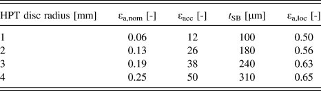
Cyclic loading was performed by CHPT, directly after the formation of the UFG structure via monotonic HPT. During CHPT the rotation of the lower anvil is simply changed from continuous to alternating twist mode allowing the sample to be rotated for certain degrees clockwise (first half cycle) and then the rotation direction is changed to anti-clockwise for the same amount of degrees (second half cycle). The nominal cyclic strain amplitude can be simply calculated from the applied twist angle shown in Table I. Due to experimental reasons the separation of the elastic and plastic part is not possible. Equation (2) shows the dependence of the cyclic strain amplitude on the HPT twist angle, θ, the thickness of the HPT disc and also on the HPT disc radius:
 $${\varepsilon _{\rm{a}}} = {{2\pi r} \over {\sqrt 3 t}}{\theta \over {360^\circ }}\quad .$$
Nominal strain amplitudes, εa,nom, accumulated strain, εacc, thickness of the shear band, t SB, as marked in Fig. 1 and local strain amplitude, εa,loc, for samples cycled to 5° for 50 times are listed for HPT disc radii 1, 2, 3, and 4 mm. The local strain amplitude is estimated with Eq. (2) by setting t = t SB.

The accumulated strain can be modified by changing the number of cycles, N, according to Eq. (3):
 $${\varepsilon _{{\rm{acc}}}} = 4 \times {\varepsilon _{\rm{a}}} \times N$$
and is shown in Table I for samples cycled to θ = 5° for N = 50, which will be presented in this study.
In conventional fatigue experiments hysteresis loops are recorded to allow for an investigation of the cyclic stability. In the case of CHPT a continuous measurement of the torque is in principle possible, although the measured torque does not correspond solely to the flow stress. Reference Wetscher and Pippan30 A much more reliable technique to quantify cyclic softening is to measure the microhardness along the HPT disc radius.
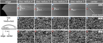
In addition to the microhardness the microstructural stability was evaluated by back scatter electron (BSE) images recorded along the HPT disc radius in TAN direction (see insert Fig. 1). Furthermore EBSD was used to investigate the crystallographic orientation as well as the grain boundary misorientation of the cycled samples. These structural investigations were carried out at exactly the same positions where the microhardness was measured, which allows directly to correlate cyclic softening to structural parameters.
Formation of shear bands in the middle of the HPT disc height, with its thickness, t SB, increasing from the center towards the edge for 5° and 50 cycles (first row). The grain size outside the shear band has not changed significantly (second row), whereas inside the shear band grains are coarser and elongated along the radial direction (third row).

III. RESULTS
A. Shear band formation
Investigating the cross section of a HPT disc cycled 50 times for 5° by BSE images revealed two different regions with different contrast (Fig. 1, first row). A bright region in the middle of the disc height is surrounded by a darker region at the top and bottom of the disc. BSE images taken at higher magnification revealed a grain size and an equiaxed grain shape similar to the as-deformed material in the outer darker regions (Fig. 1, second row), whereas in the bright region a shear band has formed. Inside the shear band the grains are larger and appear elongated in the radial direction (Fig. 1, third row). No significant change of the grain size and the grain shape is observed along the HPT disc radius, although the nominal strain amplitude increases. However, the width of the shear band, t SB, increases with increasing nominal strain amplitude along the HPT disc radius, forming a wedge shaped region throughout the disc (Fig. 1).
B. Microhardness
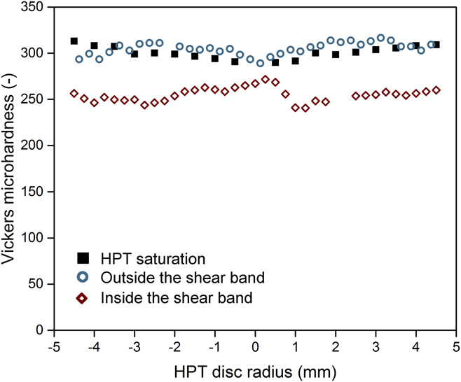
Microhardness measurements shown in Fig. 2 were conducted along the HPT disc radius in tangential direction (see TAN in insert of Fig. 1). Thus, modification of mechanical properties due to CHPT as a function of the changing nominal strain amplitude could be tracked. Microhardness was determined inside and outside of the shear band to clarify the effect of the different grain sizes. For a sample cycled for 50 times at a twist angle of 5°, the microhardness inside and outside the shear band differs significantly (Fig. 2). Outside the shear band the microhardness along the HPT disc radius (blue empty dots) remained at about 305 HV almost constant compared to the microhardness of the as-HPT deformed discs (black full squares). Within the shear band the microhardness (red empty rhomboids) drops by 20% down to about 255 HV. No distinct correlation between the nominal strain amplitude and the hardness is visible and the hardness within the shear band remains nearly constant along the HPT disc radius. Although slight scatter can be observed along the disc radius, it is distinctively smaller than the differences between the areas outside the shear band and the as-deformed condition.
The Vickers microhardness inside the shear band drops by about 20% after cyclic loading at 5° for 50 cycles, whereas outside it remains nearly the same compared to the as-HPT deformed state.

C. Microstructural evolution
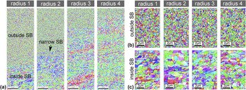
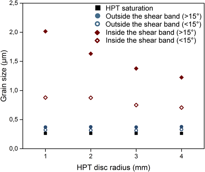
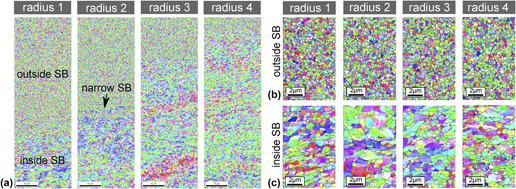
As evident from the BSE images (Fig. 1), the grain size differs significantly inside and outside of the shear band. The same trend is visible in EBSD scans taken along the radius of the disc [Fig. 3(a)], where a sharp transition from a coarsened to a still UFG region is visible. The fraction of the coarsened region increases with increasing HPT disc radius, thus nominal strain amplitude, similar to the BSE images in Fig. 1. For detailed insights into the grain structure EBSD scans were performed at higher magnification in the UFG region outside the shear band [Fig. 3(b)] and in the already heavily coarsened region within the shear band [Fig. 3(c)] along the HPT disc radius in tangential direction. Mostly HAGB (misorientation >15°, see black lines) accumulate in the structure, although in the larger grains additional cell boundaries of low angle type with misorientation between 2 and 15° also appear. In Fig. 4 the structural sizes were analyzed for boundary misorientation angles of 2–15° (LAGB, empty symbols) and >15° (HAGB, full symbols) for both outside (circular symbols) and inside (rhomboid symbols) of the shear band. Although the structure outside the shear band does not seem to have coarsened significantly, grain size analysis revealed already a growth in size of about 20%. While the HPT steady state grain size was 310 nm taking into account HAGB after cyclic deformation it has grown up to 373 nm on average outside the shear band. However, this is clearly less pronounced compared to the grain growth within the shear band. Contrary to the observations from BSE images a strain amplitude dependency becomes visible, which is stronger if HAGB are considered. Both structural sizes increase with decreasing nominal strain amplitude (Fig. 4). For the smallest nominal strain amplitude at a radius of 1 mm the average grain size (HAGB, ≥15° boundary misorientation) became more than 6 times larger compared to the initial steady state structure. It should be noted that the measured structural sizes delineated by HAGB can only be considered as a lower bound, as the edge grains of the scan have exceeded the EBSD scan size and were therefore cut off. The scanning area chosen reflected a compromise between retaining sufficient resolution to detect small grains and minimizing scanning time to avoid sample drift.
(a) EBSD scans were taken in tangential direction along the border between the major shear band and the matrix for a sample cycled 50 times at an HPT twist angle of 5°. The thickness of the shear band clearly increases with increasing nominal strain amplitude. At an HPT disc radius of 2 mm an additional narrow shear band is visible nearby the major one. EBSD scans of higher magnification taken (b) outside and (c) inside the shear band prove a severe coarsening of the grain structure within the shear band.

During cyclic loading the structural size calculated for boundary misorientation >15° (HAGB, filled symbols) and subgrains (2–15° boundary misorientation, open symbols) significantly increases inside the shear band (red rhomboids). Even outside the shear bands (blue circles) slight coarsening can be noticed. Grain sizes for the as-HPT deformed starting material are given for comparison (black squares).

D. Crystallographic orientation
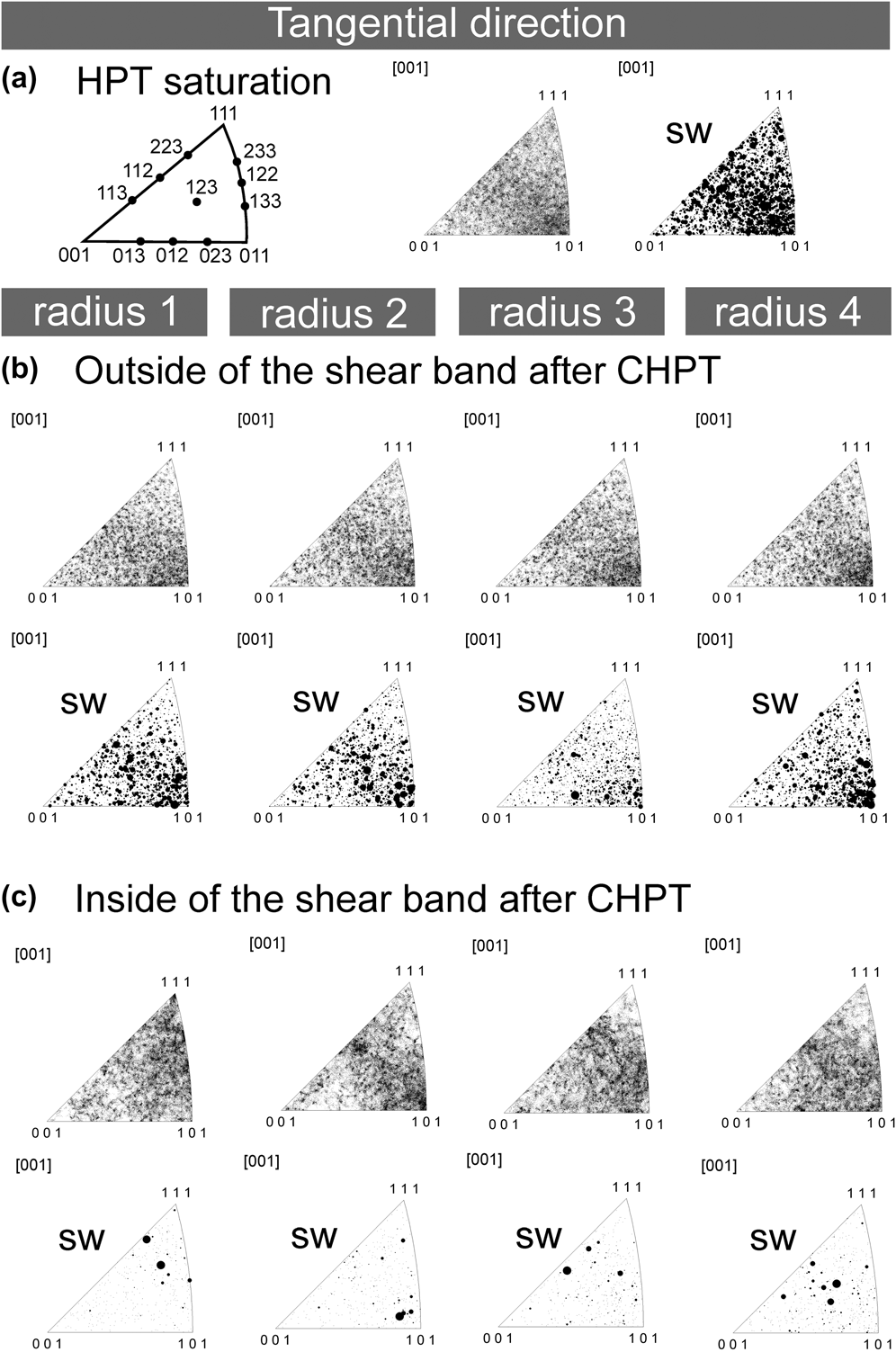
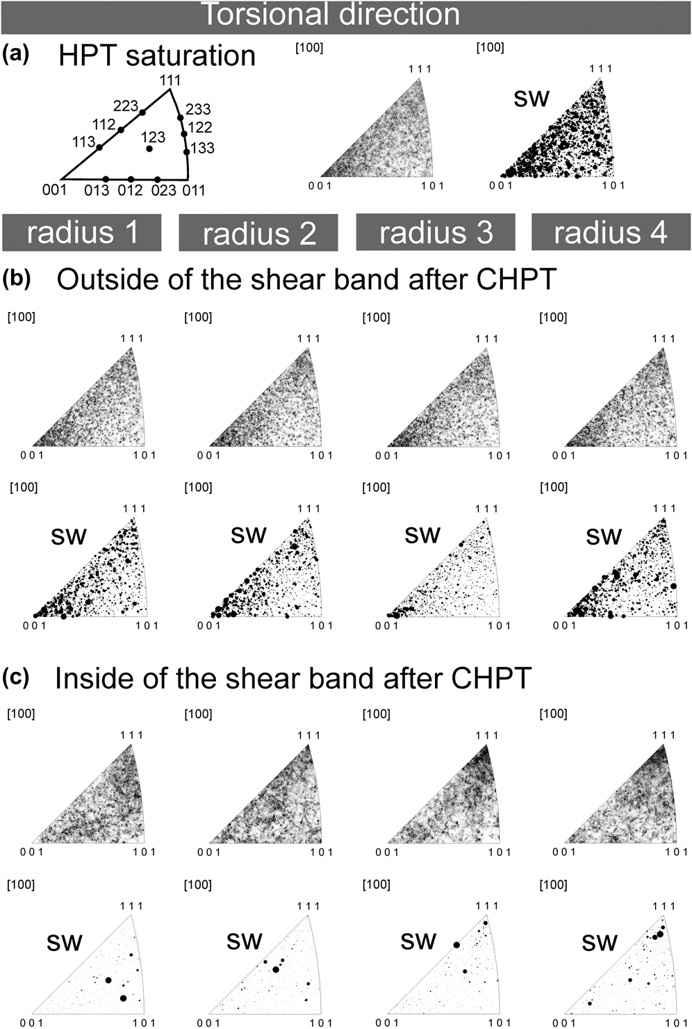
The full crystallographic information of the EBSD scans taken from areas outside and inside of the shear band [Figs. 3(b) and 3(c)] allows for an analysis of orientation changes induced by CHPT. For an easier interpretation the data are plotted in inverse pole figures (IPF) in two directions (tangential, torsional, compare TAN and TOR in inset of Fig. 1) instead of ODF sections. Figures 5 and 6 show IPF maps for the as-HPT deformed structure [TAN in Fig. 5(a), TOR in Fig. 6(a)] and for the same structure subjected to CHPT inside [TAN in Fig. 5(b), TOR in Fig. 6(b)] and outside of the shear band [TAN in Fig. 5(c), TOR in Fig. 6(c)] at different disc radii, respectively. Each data point in the conventional IPF maps (not marked by sw in Figs. 5 and 6) corresponds to the crystallographic orientation of one analyzed grain. Additionally, each of these data points can be weighted by the size (sw) of the corresponding grain, with larger dot sizes corresponding to grains of larger size (marked by sw for size-weighted in Figs. 5 and 6). The monotonically deformed steady state structure exhibits a typical shear texture observed for medium or high stacking fault energy fcc metals Reference Schafler and Pippan31,Reference Ghosh, Renk and Pippan32 [TAN in Fig. 5(a) and TOR in Fig. 6(a)]. The shear texture is not very pronounced although 〈110〉 directions align parallel to the shear direction (TAN direction) and {100} planes (TOR direction) are preferred, corresponding to the ideal texture components of shear. Reference Toth, Gilormini and Jonas33 Similar trends can be observed in the size-weighted IPFs, from which it is clear that large grains have a higher tendency for these orientations. After CHPT the crystallographic orientation outside the shear band [TAN in Fig. 5(b) and TOR in Fig. 6(b)] progressively changes to some extent with increasing HPT disc radius. For larger radii, thus higher nominal strain amplitudes, [101] orientations become more intense in tangential direction and {001} and {111} in torsional direction especially for larger grains [see sw IPF in Figs. 5(b) and 6(b)]. In tangential direction inside the shear band [Fig. 5(c)] a preference for [110] and [112] directions parallel to the shear direction is visible in the IPFs. The major difference from the as-HPT deformed structure is the reduced number of analyzed points in the size-weighted IPFs due to grain coarsening and therefore a reduction in the number of analyzed grains. However, compared to the region outside the shear band and the monotonically deformed sample a clear preference of {111} planes parallel to the shear plane can be noticed [Fig. 6(c)].
Inverse pole figure (IPF) maps from (a) the as-HPT deformed structure (first image) were compared to the cycled structure (b) outside and (c) inside of the shear band (first row each) with respect to the tangential (TAN) direction of the HPT disc. Further the IPF maps were weighted by the size (marked by sw) of the analyzed grain second image in (a) and second row each in (b, c). The dot size scales with the size of the analyzed grain.

Inverse pole figure (IPF) maps from (a) the as-HPT deformed structure (first image) were compared to the cycled structure (b) outside and (c) inside of the shear band (first row each) with respect to the torsional (TOR) direction of the HPT disc. Further the IPF maps were weighted by the size (marked by sw) of the analyzed grain second image in (a) and second row each in (b, c). The dot size scales with the size of the analyzed grain.

IV. DISCUSSION
Two types of structural instabilities developed during CHPT of high purity UFG Ni: (i) coarsening of the initially UFG grained structure and (ii) formation a shear band. The first case has been reported frequently for NC and UFG metals not only under fatigue Reference Mughrabi, Höppel and Kautz1,Reference Agnew and Weertman14,Reference Canadinca, Niendorf and Maier16–Reference Kapp, Kremmer, Motz, Yang and Pippan18,Reference Kunz, Lukáš, Pantelejev and Man34–Reference Glushko and Cordill37 but also under static loading conditions for a variety of materials. Reference Gianola, van Petegem, Legros, Brandstetter, van Swygenhoven and Hemker5–Reference Yang, Vehoff, Hohenwarter, Hafok and Pippan12,Reference Brandstetter, Zhang, Escuadro, Weertman and van Swygenhoven38–Reference Mompiou and Legros40 The formation of shear bands has also been observed macroscopically at the surface Reference Agnew and Weertman14,Reference Kunz, Lukáš and Svoboda15,Reference Höppel, Xu, Kautz, Barta-Schreiber, Langdon, Mughrabi, Zehetbauer and Valiev19,Reference Agnew, Vinogradov, Hashimoto and Weertman24–Reference Wu, Wang, Jiang, Li, Alexandrov and Valiev27,Reference Kunz, Lukáš, Pantelejev and Man34 and in the sample interior of cyclically deformed materials. Reference Wong, Kao, Lui, Chang and Kao29 However, the combination of both instability mechanisms namely the observation of grain coarsening within shear bands has been shown for the very first time by Höppel et al. Reference Höppel, Xu, Kautz, Barta-Schreiber, Langdon, Mughrabi, Zehetbauer and Valiev19 and could be confirmed in this study. Although possible, a persistent instability type of these fine scaled structures for specific loading situation or materials was not reported. Thus, it remains unclear why and how these instabilities form and develop. The use of CHPT allows the tracking of the evolution of such instabilities, as the experiment is not restricted by the rupture of the fatigue sample. The main questions to be answered are the driving forces for grain growth, why do shear bands form and how the loading conditions affect the occurrence and development of these instability mechanisms. Only a thorough understanding of these fundamental points will allow to develop nanostructured materials being resistant against the formation of such instabilities.
As mentioned, shear band formation can be frequently observed in nanostructured materials, but also during deformation of coarse grained materials. Reference Carsley, Fisher, Milligan and Aifantis41,Reference Duggan, Hatherly, Hutchinson and Wakefield42 In any case a shear band reflects a strain localization, which can be further promoted in case of limited work hardening, such as for severely deformed materials. Although generally there can be various reasons for shear band formation, Reference Humphreys and Hatherly43 for cyclic deformation of UFG structures it appears that grain coarsening causes local softening. The microhardness measurements of CHPT samples show that grains and subgrains can grow up to about 2000 and 880 nm, respectively, leading to a drop in the microhardness of 20%. Two explanations for the shear band initiation could be imagined: (i) grains coarsen as a response to cyclic deformation causing local softening and thereby promote strain localization in these softer regions or (ii) due to the stress- and strain concentration at the edge of the HPT disc a shear localization develops through the middle of the disc, thereby amplifying grain growth within this region. Similar explanations for case (i) already exist to describe instabilities in cyclically deformed coarse grained materials, where persistent slip bands develop above a certain strain amplitude. Reference Finney and Laird44 These structures consist of channels of low dislocation density, thus softer regions, where dislocations can realize the cyclic strain more easily by moving forth and back. A similar explanation for the simultaneous occurrence of shear bands and grain coarsening in cyclically loaded UFG Al was utilized earlier by Höppel et al. Reference Höppel, Xu, Kautz, Barta-Schreiber, Langdon, Mughrabi, Zehetbauer and Valiev19 The evolution of shear bands was attributed to the local softening induced by growth and rotation of adjacent grains. On the other hand, case (ii) cannot be neglected as from Fig. 1 it is evident that the shear band formation will start at the disc edge, a location of maximum strain concentration, and develop almost completely through the middle of the disc after 50 cycles of deformation. Additionally, grain coarsening does also occur outside of the shear band, though less pronounced, but does not result in the formation of a large scale shear band. Thus, a conclusion about the exact mechanism generating a shear band cannot be drawn so far.
However, it is evident that grain coarsening is distinctively amplified in the shear band region. It is shown in Fig. 4 that grain growth occurs inside and outside of the shear band, but the grain size (HAGB, ≥15° boundary misorientation) within the shear band is more than 5 times larger than outside of it. As the starting grain size, the flow stress, texture and boundary characters of the monotonically deformed UFG Ni will be similar before CHPT, but the strain is localized in the shear band, it is evident that grain growth is enhanced significantly by the cyclic strain. The importance of the cyclic strain found in this study is deviating from earlier studies about shear-stress coupled boundary migration. Reference Rupert, Gianola, Gan and Hemker7 In situ TEM tension experiments at elevated temperatures on UFG Al revealed a migration of a HAGB immediately after a stress increment. However, this argument does not hold for grain growth during CHPT as the same stress is initially applied over the disc height, yet grain growth is concentrated in the middle of the disc (Figs. 1, 3, and 4). Even though at higher cycle numbers the local stresses will become higher in the outer regions due to the somewhat smaller grains, the coarsening process is still accelerated in the middle of the disc. The importance of the strain for grain coarsening has also been shown in static tensile experiments on nanogradient structures Reference Fang, Li, Tao and Lu39 and in cyclic micro bending experiments. Reference Kapp, Kremmer, Motz, Yang and Pippan18 There it was reported that in UFG structures grain growth proceeds by a continuous migration of HAGBs, which can be also assumed to occur for torsional cyclic deformation. Because the IPFs in Figs. 5 and 6 show the presence of ideal shear texture components outside and inside of the shear band after CHPT, Reference Ghosh, Renk and Pippan32,Reference Toth, Gilormini and Jonas33 dislocation based plasticity will prevail and their interactions with grain boundaries may induce the migration of the boundary. Therefore, grain coarsening in UFG structures induced by cyclic loading cannot be explained by recrystallization as suggested in earlier works, Reference Mughrabi, Höppel and Kautz1 as different texture components would have to appear.
Coarsening within the shear band occurred preferentially in grains having their (111) plane oriented parallel to the shear plane (torsional direction) and the [110] direction parallel to the shear direction [Fig. 5(c); tangential direction, see Fig. 6(c)]. Compared with earlier studies on torsional deformation of Toth et al. Reference Toth, Gilormini and Jonas33 this crystallographic orientation requires the activation of only one single slip system to realize the torsional strain. Grains with this orientation can probably accommodate the intense cyclic strain within the shear band in a more efficient manner. Thus, enhanced plasticity might occur in these grains. The repeated interaction of dislocations with grain boundaries might induce the continuing formation of disconnections Reference Rajabzadeh, Legros, Combe, Mompiou and Molodov45 whose motion will cause migration of corresponding grain boundaries leading to grain coarsening. Similar reasons may explain also frequent occurrence of coarsened grains with their [112] direction parallel to the shear direction. Although this texture component requires the activation of a second slip system, these slip systems are coplanar and possibly induce less dislocation interaction than for the other orientations, making this orientation also preferable for cyclic slip. In regions outside the shear band [Figs. 5(b) and 6(b)] only microplasticity is assumed to take place, which could explain the retention of the monotonic torsional texture components. Coarsened grains in the region outside the shear band at radius 4 mm have a tendency for (100) planes parallel to the shear plane and the [110] direction parallel to the shear direction. This ideal orientation known as “C” component requires the activation of two noncoplanar slip systems. This may induce more dislocation interactions, thus, reducing interaction of dislocations with grain boundaries.
As the strain seems to accentuate the coarsening process, it is necessary to discuss the effect of the strain amplitude as well. A comparison of the grain coarsening inside and outside the shear band suggests that larger strain amplitudes cause enhanced grain growth. However, within the shear band grains at smaller radii, i.e., reduced nominal strain amplitude, grow larger in size than at the edge of the disc (Fig. 4), contrary to what would be expected. It is important to note that the effective strain amplitude within the shear band will differ remarkably from the nominal one due to the varying thickness of the shear band. To estimate the effective strain amplitude within the shear band we assume the plastic strain to be entirely concentrated in the shear band and the matrix outside the shear band to deform microplastically. As grain growth outside the shear band is not pronounced (Fig. 4), this estimation should yield reasonable values. The local strain amplitude can then be calculated by normalizing the nominal strain amplitude by the shear band thickness, see Eq. (2) in that case with t = t SB. This yields for 50 loading cycles to local strain amplitudes inside the shear bands of 0.50, 0.56, 0.63, and 0.65 at HPT disc radii of 1, 2, 3, and 4 mm, respectively. Although under this considerations the local strain amplitude differences are less pronounced compared to the nominal ones (see Table I), they still increase with increasing radii. Nevertheless, observing larger grain sizes at smaller strain amplitudes upon CHPT is not contradictory with the observations that the coarsening process is primarily strain driven at low temperatures. Earlier results of CHPT deformed nickel and iron Reference Wetscher and Pippan30 have already shown that for large strain amplitudes (εa,pl ∼ 1), the structural size will be smaller at higher applied strain amplitudes. This trend has been explained with the understanding that at such large strain amplitudes present also within the shear bands structural refinement will occur as in monotonic HPT, thus subduing the coarsening process. Of course, this effect will diminish for small strain amplitudes as usually applied in LCF experiments (εa,pl ∼ 0.001–0.01) and the frequently observed trend of an amplifying effect of the strain amplitude on the coarsening process Reference Kunz, Lukáš and Svoboda15,Reference Canadinca, Niendorf and Maier16 will prevail.
As mentioned earlier, distinct cyclically induced softening of about 20% occurs in the region of the shear band. This is attributed to the pronounced growth of grains and subgrains in the presence of strain localization. A reduction of the dislocation density within grains may take place, but will not contribute to a significant decrease in microhardness. Reference Schafler and Pippan31 The evolution of the hardness does not show a correlation with the nominal strain amplitude in contrast to the grain size (HAGB, >15° boundary misorientation in Fig. 4). Their exceptional growth of more than 6 times at a radius of 1 mm does not correlate to the drop of 50 HV in microhardness. The moderate size dependence of subgrains on the nominal strain amplitude and their less pronounced coarsening suggests that the subgrain boundaries are the crucial barriers for dislocations and therefore govern the materials strength.
V. CONCLUSION AND OUTLOOK
CHPT experiments were performed on UFG Ni samples and led to the observation of cyclic instability mechanisms, namely shear banding and grain coarsening. The goal of the present investigation was to show the details of the evolved grain size, texture, boundary structure within a shear band and outside of it for a defined number of loading cycles (N = 50) and consequences with respect to cyclic grain coarsening. The experimental setup prevents fatigue crack initiation and rupture due to a sample constraint–in principle up to infinite accumulated strain. Therefore, the cyclic softening portion stemming solely from grain coarsening could be quantified and was measured by a drop of 20% in the microhardness due to a grain size and subgrain size increase of more than 6 and 3 times, respectively. Furthermore, it was found that grain coarsening is distinctively amplified in regions of shear localization, strengthening the concept of deformation driven boundary migration. This was supported by IPF maps revealing the evolution of shear texture components with increasing cyclic strain.
Details to the evolution of the shear band width as a function of loading cycles and the maximum applied shear strain, i.e., applied angle amplitude, the effect of temperature and initial structure are the subject of ongoing investigations.
ACKNOWLEDGMENT
Financial support by the FWF Austrian Science Fund within project number P24429-N20 is gratefully acknowledged.