Introduction
In recent years, sub-6 GHz antennas operating in the mid-band frequency between 3.4 and 3.6 GHz hit the spotlight as they exhibit wider coverage with fewer propagation losses. However, designing a wideband antenna by eliminating undesired frequencies is quite challenging since it covers a large bandwidth in the passband frequency. Though the bandwidth requirement is satisfied, achieving a stable gain for the required application is an essential task. In addition, the interference between the elements should be eliminated to obtain a noise-free transmission of radio frequency signals. To obtain this, a wideband filtering monopole operating in sub-6 GHz is proposed with simple structural modifications. Using the miniaturization technique and modified resonator structures, the performance is analyzed for filtering monopole subject to bandwidth, efficiency, and insertion loss, by which a simple and compact MIMO array is constructed.
Many studies have been reported on wideband filtering antenna design [Reference Chen1–Reference Aboelleil, Ibrahim and Khalaf24]. According to the literature, wideband filtering can be achieved in four ways, using filters and stacked structures, using defected ground structure (DGS) and slots, loading parasitic circuits, or combining all three methods. A few filtering techniques like a slot-loaded filter that is coupled to a coplanar L-probe feed [Reference Chen1], parasitic radiator and a reflector [Reference Chen2], balanced planar antenna with a symmetric bandpass filter [Reference Lee, Chen, Shih and Hsu3], a meta surface antenna with defected ground structure (DGS) and a U-shaped slot without any extra circuits [Reference Yang, Chen, Xue, Che, Shen and Feng4], a broadband coupling resonator [Reference Singh, Siva Prasad and Tripathi5], T-shaped slots [Reference Li, Yin and Zhu6, Reference Zhang and Zhang7], stacked patches with substrate integrated suspended line [Reference Alsultan and Yetkin8], and a slot line radiator with dual-mode resonator [Reference Nithya and Seethalakshmi9]were reported in literature. However, these techniques result in larger volume [Reference Chen1–Reference Yang, Chen, Xue, Che, Shen and Feng4], complex structures [Reference Chen2, Reference Lee, Chen, Shih and Hsu3], narrow bandwidth [Reference Chen1, Reference Yang, Chen, Xue, Che, Shen and Feng4], and low efficiency [Reference Chen2, Reference Lee, Chen, Shih and Hsu3, Reference Zhang and Zhang7, Reference Nithya and Seethalakshmi9]. While constructing a MIMO array using these filtering antennas, certain metrics such as envelope correlation coefficient (ECC), isolation, and diversity gain (DG) have to be met to avoid signal weakening and interference among the adjacent radiators. In the literature, various techniques were reported in MIMO construction, such as a decoupling circuit [Reference Zhang and Zhang7], a C-shaped resonator in electronic band gap structure [Reference Alsultan and Yetkin8], pattern diversity technique [Reference Nithya and Seethalakshmi9], parallel coupled lines, open-circuited stub lines [Reference Qian, Chen, Ding, Hu and Chu10], resonators, filters [Reference Zhang, Zhang and Liu11], folded slots [Reference Soltani and Murch12], inverted L-shaped parasitic elements [Reference Raj, Madan Kumar, Javed and Sharma13], un-protruded multi slots [Reference Kulkarni, Desai and Sim14], a wideband neutralization line [Reference Thummaluru, Kumar and Chaudhary15], meta surface [Reference Hasan, Islam, Samsuzzaman, Baharuddi, Soliman, Alzamil, Abu Sulayman and Shabiul Islam16–Reference Aashish Kumar, Khandelwal and Kanaujia18], an annular ring with gap coupled shorting [Reference Wong, Chen and Li19], a square slot ring radiator with circular ring parasitic structures [Reference Parchin, Ismael Abdulraheem Al-Yasir, Ali, Elfergani, Noras, Rodriguez and Abd-Alhameed20], X-shaped isolation block [Reference Molins-Benlliure, Antonino-Daviu, Cabedo-Fabrés and Ferrando-Bataller21], and stub lines with DGS [Reference Alsath and Kanagasabai22–Reference Khan, Naqvi, Iftikhar, Asif, Fida and Shubair25]. In an orthogonally placed MIMO array, the ground plane is not connected [Reference Li, Yin and Zhu6, Reference Qian, Chen, Ding, Hu and Chu10, Reference Raj, Madan Kumar, Javed and Sharma13, Reference Kulkarni, Desai and Sim14, Reference Hasan, Islam, Samsuzzaman, Baharuddi, Soliman, Alzamil, Abu Sulayman and Shabiul Islam16, Reference Parchin, Ismael Abdulraheem Al-Yasir, Ali, Elfergani, Noras, Rodriguez and Abd-Alhameed20] resulting in discontinuity of conducting medium such that no coupling current flows through the ground plane. In some literature [Reference Qian, Chen, Ding, Hu and Chu10, Reference Zhang, Zhang and Liu11, Reference Raj, Madan Kumar, Javed and Sharma13, Reference Molins-Benlliure, Antonino-Daviu, Cabedo-Fabrés and Ferrando-Bataller21], the interelement spacing is larger, which leads to a larger size and it affects the spatial diversity of the antenna element. Some literature [Reference Singh, Siva Prasad and Tripathi5, Reference Li, Yin and Zhu6, Reference Qian, Chen, Ding, Hu and Chu10, Reference Kulkarni, Desai and Sim14, Reference Parchin, Ismael Abdulraheem Al-Yasir, Ali, Elfergani, Noras, Rodriguez and Abd-Alhameed20] use extra circuits to obtain enhanced isolation. Though many techniques were suggested to design an MIMO antenna using the filtering concept, it is quite a complicated task to configure a simple, low-profile, and compact antenna with stable gain and high isolation.
In this work, a simple four-port MIMO array is modeled using a wideband filtering monopole antenna. The motivation starts from designing a reference truncated decagonal monopole (TDM) for the desired resonant frequency. A modified-ground plane coupled to a microstrip feed line excites the antenna. A simple and compact low-pass filter (LPF) structure is proposed using a modified split-ring resonator (MSRR). The filter is integrated with the reference monopole and its wideband performance is analyzed. The basic element of the four-port MIMO array is the proposed wideband filtering antenna which is formed by orthogonally placing the elements and their key metrics were analyzed and compared. The proposed design is fabricated with the optimized dimensions and the reliability of the fabricated prototype is tested in the anechoic chamber. The simulated values correlate with the measured values.
Design methodology
Design of MP-fed filtering TDM
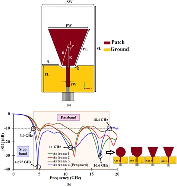
Figure 1 illustrates the layout of the reference TDM, its design evolution, and the corresponding S parameters. A reference TDM is etched on an FR4 substrate of thickness 0.8 mm. To obtain an ultrawideband response, two structural modifications are made in the antenna. Firstly, the upper and lateral edges of the patch are truncated by a quarter wavelength dimension making the antenna purely resistive such that a maximum current flow through the edges of the radiator results in optimum radiation. Secondly, the ground plane is made partial and defected to obtain proper impedance matching between the elements.
(a) Reference Microstrip-fed TDM antenna. SW = 20 mm, SL = 30 mm, PW = 7 mm, PL = λ/4 mm, R = 7 mm, r = 0.8 mm, FL = 9.35 mm, FW = 1.2 mm, S = 6.94 mm, g = 1.2 mm. (b) Evolution of TDM antenna and its simulated output.

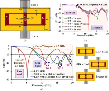
As a result, a −10 dB fractional bandwidth (FBW) of 130% is achieved (3.9–18.4 GHz) with a maximum gain of 6 dBi at 11.7 GHz. To obtain a wideband response, a simple LPF is proposed using an MSRR as depicted in Fig. 2(a). The cut-off frequency of the filter is 6.5 GHz and is excited by a two-port network. The main focus in filter design is to attain resonance at the cut-off frequency with minimum structural modification. This is influenced by introducing a slot in the feedline. The control over the attainment of resonant frequency is solely bounded by the position and the width of the slot. The slot in the feed line is represented by the variable W 5 (0.6 mm) induces a capacitive effect leading to maximum current flow in the filter structure. To increase the occurrence of transmission zeros and to improve the stopband performance, the SRR is modified by introducing an inductance (W 7) in the slot. As depicted in Fig. 2(b), the stub length W 7 has an inevitable impact on the stopband performance of the filter. When W 7 varies for a certain value (4 mm), the |S 21| response beyond 14.5 GHz gets attenuated below −10 dB resulting in wide stopband performance between 14.5 and 20 GHz which is demonstrated in Fig. 2(b). As transmission zero increases, the stopband characteristic also increases thereby increasing the signal-to-noise ratio. From Fig. 2(c) three transmission zeros were identified in the stopband frequencies 11.9, 16, and 19.45 GHz. This helps to attain proper impedance matching between the filter and the reference TDM antenna.
(a) Proposed LPF with modified SRR; L 1 = 4.7 mm, L 2 = 4.22 mm, W 1 = 16.2 mm, W 2 = 13 mm, W 3 = 0.24 mm, W 4 = 0.2 mm, W 5 = 0.6 mm, W 6 = 1.6 mm, W 7 = 4 mm. (b) |S 21| response for various values of W 7. (c) Simulated response of proposed MSRR LPF at each stage of evolution.

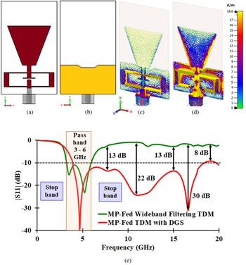
To comprehend the working methodology of the proposed modified LPF, the filter is integrated with the reference monopole forming a wideband filtering monopole antenna. Figure 3(a) represents the front view and Fig. 3(b) represents the back view of the MP-fed wideband filtering TDM whereas Figs 3(c) and 3(d) demonstrate the surface current analysis of the wideband filtering TDM at the stopband frequency 7.2 GHz and passband frequency 3.7 GHz. At passband frequency, the proposed wideband filtering TDM radiates effectively through the truncated lateral edges of the patch; whereas, in the stopband frequency, the radiation is completely cut-off within the filter area before reaching the patch. Figure 3(e) demonstrates the comparative analysis of reflection characteristics of reference monopole and proposed wideband filtering TDM. The proposed filtering monopole covers a wide bandwidth (3–6 GHz) with an enhanced stopband characteristic between 6 and 20 GHz, respectively. Figure 3(e) shows an average out-of-band rejection level of 15 dB throughout the stopband with a minimum suppression level of 8 dB and a peak suppression level of 30 dB. To avoid a mismatch between the filter and reference TDM, the coupling effect between the filter and the reference TDM antenna is analyzed based on the terminal impedance in both real and imaginary values.
Schematic of proposed MP-fed wideband filtering TDM with DGS using MSRR LPF. (a) Front view. (b) Back view. Perspective view of the surface current distribution of proposed MP-fed wideband filtering TDM at (c) stopband frequency 7.2 GHz and (d) passband frequency 3.7 GHz. (e) Reflection performance comparison of MP-fed TDM and wideband filtering TDM.

MIMO array construction
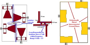
A four-port 2 × 2 MIMO array is constructed by orthogonally placing the wideband filtering monopole antenna elements. The array has an overall dimension of 40.5 mm × 60 mm × 0.8 mm. The adjacent elements in the array are tightly packed such that the center-to-center spacing between each element is reduced in the range of 0.22λ 0 to 0.25λ 0. Fig. 4 illustrates both the front view of the MIMO element with an isolation network and the back view with interconnected ground planes of the proposed MIMO element and the isolation circuit.
Front views of orthogonally placed MIMO antenna with isolation network and back view of interconnected ground planes.

Effect of interconnected ground planes
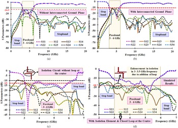
The isolation between the elements is enhanced by implementing one of these two techniques or by combining both techniques. One is reducing the coupling effect among the radiating components caused by the surface waves linking the antenna parts. The other is to diminish mutual coupling by perturbing the current flow direction in the ground plane. In the proposed design, the ground plane is undisturbed and the modifications are done amidst the antenna elements. Initially, the ground planes are not connected and a thorough analysis is done on the isolation part between the radiating patches. As described in Fig. 5(a), the isolation obtained is 14.3 dB without interconnecting the ground planes. The same analysis is done by interconnecting the ground planes (Fig. 5(b)), and an isolation of 11.4 dB is observed which is lesser than in the previous case. This shows that the ground planes are discontinuous in the first case and cannot be assumed that a uniform current/voltage flows throughout the ground plane. Furthermore, the isolation parameter has a direct impact on the distribution of current over the ground plane which is clear from the second case.
(a) Isolation without an interconnected ground plane and stub lines. (b) Isolation with interconnected ground planes. (c) Isolation with two-inverted L-stub lines. (d) Isolation enhancement by introducing a closed loop at the center of the MIMO array.

Mutual coupling and isolation enhancement
To lower the mutual coupling effect experienced between the antennas, a pair of inverted L stubs of varying lengths are inserted at the center of the MIMO array as pictured in Fig. 5(c). The direction of the current flow between these ports gets reversed resulting in reasonable isolation >13 dB beyond 3 GHz and >15 dB beyond 3.5 GHz. However, between 3 and 3.5 GHz, isolation is 13 dB. To enhance isolation within this frequency range, a closed loop is formed by interconnecting the inverted L stubs. Thus, isolation >18.7 dB is observed in the frequency ranging between 3 and 6 GHz as highlighted in Fig. 5(d). Beyond 6.5 GHz, the isolation is found to be >27 dB.
ECC and DG
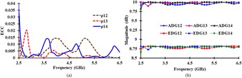
Metrics such as ECC and DG have become standard metrics based on which the design significance of the MIMO antenna is evaluated. The ECC, ADG, and EDG of the proposed design are calculated using the conventional formula given in [Reference Alsath and Kanagasabai22], and its values in the passband are plotted as displayed in Figs 6(a) and 6(b). The proposed MIMO has ECC < 0.015 and ADG > 9.8 dB. Since the DG calculation will not include radiation losses, the metrics like ADG and EDG are calculated and found to be >8.8 dB which is greater than the required 7 dB value.


(a) Envelope correlation coefficient (ECC) between ports 1, 2, 3, and 4. (b) ADG and EDG curves of the proposed MIMO antenna between ports 1, 2, 3, and 4.

Results and discussions
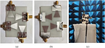
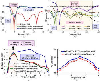
The proposed prototype is fabricated using a photolithography process and tested in the anechoic chamber as illustrated in Fig. 7. The reflection parameter values are measured using a network analyzer N9951A. The measured reflection properties results are collated with the simulated results as represented in Fig. 8(a) and are found to correlate with each other. The simulated/measured values of isolation metrics, efficiency, gain, and radiation properties of the antenna in both the elevation plane and azimuth plane are compared. From Fig. 8(a) wide stopband characteristics are observed within the frequency of 6.5–20 GHz.
Fabricated prototype (a) front view and (b) back view. (c) Testing in an anechoic chamber.

(a) Comparative analysis of measured/simulated S parameters of reference TDM and wideband filtering TDM. (b) Measured results of isolation curve of proposed MIMO array. (c) Simulated/measured realized gain comparison of the proposed four-port MIMO wideband filtering TDM with reference TDM and wideband filtering TDM. (d) Simulated/measured comparison of MIMO total efficiency.

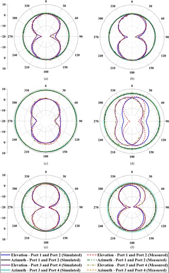
The measured isolation parameters between each port are shown in Fig. 8(b) from which an isolation of 18.5 dBi is observed. Furthermore, a peak simulated/measured gain of 3.85/3.7 dBi, in the passband frequency of 3–6/2.8–5.8 GHz, isolation >18.7/18.5 dB, and efficiency >88% is obtained as characterized in Figs 8(c) and 8(d). The radiation properties of the proposed four-port MIMO wideband filtering monopole are studied for frequencies 3.6, 4.8, and 5.2 GHz at each port separately as portrayed in Fig. 9. Figures 9(a) and 9(b) compare the simulated/measured values of ports 1, 3 and ports 2, 4 at 3.6 GHz. Figures 9(c) and 9(d) compare the simulated/measured results of ports 1, 3 and ports 2, 4 at 3.6 GHz. Similarly, Figs 9(e) and 9(f) compare the same at 5.2 GHz frequency. It is found that the simulated results and measured results are found concurrently with each other. A perfect omnidirectional and symmetrical azimuth pattern and eight-shaped elevation patterns are achieved at each radiating frequency. Furthermore, the main lobe width of each pattern remains the same in reference TDM, filtering TDM, and four-port MIMO TDM. All the calculated values are found to conform to simulated values. The deviation in the calculated values is due to the connection, calibration, and fabrication losses that are insignificant. The obtained results are matched with the existing literature to highlight the advantages and novelty of the proposed model in Table 1. The ultimate aim of the proposed module is to design a four-wideband filtering MIMO antenna with reduced structural complexity and enhanced performance.
Measured/simulated results comparison of elevation and azimuth patterns at passband frequency (a) 3.6 GHz at ports 1 and 3, (b) 3.6 GHz at ports 2 and 4, (c) 4.8 GHz at ports 1 and 3, (d) 4.8 GHz at ports 2 and 4, (e) 5.2 GHz at ports 1 and 3, and (f) 5.2 GHz at ports 2 and 4.

Comparative analysis of the proposed MIMO array

D, center–to-center separation; C, connected; NC, not connected; Gnd, ground; Iso, isolation.
A few other features are discussed below.
(1) The proposed reference TDM is 37, 25.8, 12, and 19.8% smaller compared to [Reference Chen1, Reference Yang, Chen, Xue, Che, Shen and Feng4, Reference Singh, Siva Prasad and Tripathi5, Reference Zhang, Zhang and Liu11] whereas the proposed four-port wideband filtering MIMO antenna has a compact structure compared to [Reference Zhang and Zhang7, Reference Alsultan and Yetkin8, Reference Qian, Chen, Ding, Hu and Chu10, Reference Raj, Madan Kumar, Javed and Sharma13].
(2) A simple and compact LPF is proposed using a modified SRR concept. The stopband characteristics of the |S 21| response is controlled by varying a single element instead of adjusting multiple elements in the filter. The stub length (inductance effect) W 7 has an inevitable impact on the stopband performance of the filter. When W 7 varies for a certain value (4 mm) the |S 21| response beyond 14.5 GHz gets attenuated below −10 dB resulting in wide stopband performance between 14.5 and 20 GHz.
(3) The reference TDM has a bandwidth of 130% (3.9–18.4 GHz), the proposed wideband filtering monopole possesses a bandwidth of 66.67% (3–6 GHz), and the four-port MIMO antenna has a bandwidth of 66.67% (3–6 GHz) which is greater than [Reference Li, Yin and Zhu6, Reference Qian, Chen, Ding, Hu and Chu10, Reference Zhang, Zhang and Liu11, Reference Thummaluru, Kumar and Chaudhary15, Reference Khan, Naqvi, Iftikhar, Asif, Fida and Shubair25].
(4) The proposed four-port MIMO module has a peak gain >3.7 dBi at 5.2 GHz which is greater than [Reference Kulkarni, Desai and Sim14, Reference Thummaluru, Kumar and Chaudhary15, Reference Khan, Naqvi, Iftikhar, Asif, Fida and Shubair25].
(5) It shows an average out-of-band rejection level of 15 dB in the frequency ranging from 6 to 20 GHz, thereby enhancing the stopband behavior of the antenna resulting in a high signal-to-noise ratio.
(6) The proposed four-port MIMO shows isolation >18.5 dB which is larger compared to the works reported in [Reference Li, Yin and Zhu6, Reference Zhang, Zhang and Liu11, Reference Kulkarni, Desai and Sim14, Reference Thummaluru, Kumar and Chaudhary15, Reference Hasan, Islam, Samsuzzaman, Baharuddi, Soliman, Alzamil, Abu Sulayman and Shabiul Islam16, Reference Aboelleil, Ibrahim and Khalaf24, Reference Khan, Naqvi, Iftikhar, Asif, Fida and Shubair25]. This is achieved by introducing a pair of interconnected inverted L-stubs of asymmetric lengths.
(7) The center-to-center spacing between the adjacent elements in the four-port MIMO antenna is reduced within the range of 0.22λ e to 0.25λ e which is smaller than [Reference Li, Yin and Zhu6, Reference Qian, Chen, Ding, Hu and Chu10, Reference Zhang, Zhang and Liu11, Reference Thummaluru, Kumar and Chaudhary15, Reference Hasan, Islam, Samsuzzaman, Baharuddi, Soliman, Alzamil, Abu Sulayman and Shabiul Islam16, Reference Aboelleil, Ibrahim and Khalaf24, Reference Khan, Naqvi, Iftikhar, Asif, Fida and Shubair25].
(8) The effect of interconnected ground planes has an inevitable impact on isolation. In the proposed array, the concept of interconnected ground planes is explained properly with the attainment of isolation levels at various stages of the design.
(9) Isolation enhancement based on stub lines is explained.
Conclusion
In this letter, a four-port 2×2 MIMO array is constructed using a truncated wideband filtering monopole antenna that supports 5G sub-6 GHz applications with higher data rate communications. A reference microstrip-fed TDM with an FBW of 130% (3.9–18.4 GHz) operating with a cut-off frequency of 3.9 GHz is considered. A simple and compact LPF is designed using an MSRR for a cut-off frequency of 6.5 GHz. On integrating the filter with reference TDM, a wideband filtering TDM is obtained by which a four-port MIMO array is designed by orthogonally placing the antenna elements. The proposed design with optimized measurements is fabricated and the obtained results were compared with the simulation results. It is found that a peak gain >3.7 dBi, an efficiency >88%, good isolation >18.5 dB, ECC < 0.015, ADG > 9.9 dB, and EDG > 8.8 dB with a wide bandwidth of 66.66% are obtained. Furthermore, wide stopband characteristics are noticed within the frequency band 6–20 GHz with an average suppression level of 15 dB. Furthermore, a maximum suppression level of 30 dB and a minimum suppression level of 8 dB are observed. The proposed design is suitable for 5G sub-6 GHz n48, 77, 78, 79 bands, LTE bands 42, 43, 48, and WiMAX IEEE 802.16 (3.3–3.8 GHz) applications.
Data
No new data were generated.
Author contributions
Jasmine Vijithra A was involved in the design and paper writing. Gulam Nabi Alsath Mohammed was involved in concept generation and paper writing.
Financial support
No funding was obtained for executing this research.
Conflict of interest
None.
Code availability (software application or custom code)
The work doesn't involve any software codes.
Ethical standards
Not applicable.
Consent to participate (include appropriate statements)
Not applicable.
Consent for publication (include appropriate statements)
Not applicable.
 Jasmine Vijithra Ayyappan obtained B.E. (ECE) from St. Xavier's Catholic College of Engineering, affiliated to Anna University, Nagercoil in 2011, and M.E. (communication systems) from Joe Suresh Engineering College, affiliated to Anna University, Tirunelveli in 2013. In all, she has 9 years of experience in the field of teaching and currently is pursuing Ph.D. at Anna University. Her field of interests are antenna design, wireless communication, and signal processing. She has published a book related to antenna and wave propagation and published 13 research and project papers. She has filed a patent titled “Powerful wearables for women's safety.”
 Gulam Nabi Alsath Mohammed obtained his B.E., M.E., and Ph.D. from Anna University Chennai in 2009, 2012, and 2015, respectively. He is currently an associate professor in the Department of Electronics and Communication Engineering, SSN College of Engineering, Chennai, India. His research interests include microwave components and circuits, antenna engineering, signal integrity analysis, and solutions to electromagnetic interference problems. To his credit, he has filed 19 patents and published several research articles on antennas and microwave components in leading international journals. Also, he has presented and published research papers in the proceedings of international and national conferences. Currently, he is an associate editor in IET Microwaves Antennas and Propagation & Microwave and Optical Technology Letters.
 Dr. Sangeetha Subbaraj received an M.E. in communication systems and Ph.D. from the College of Engineering, Guindy, Anna University, Chennai. Currently she works as an assistant professor in the School of Electronics Engineering, Vellore Institute of Technology, Vellore. Her research interests are microwave sensors, tablet antennas, microwave devices, and MIMO antennas.