I. INTRODUCTION
On demand of better improvements in patient's care and quality of life in terms of preventive, diagnostic, monitoring, or therapeutic functionalities, the wireless implanted devices has drawn the attention of researchers in the past few years [Reference Kiourti and Nikita1–Reference Thotahewa, Redoute and Yuce6]. To establish wireless communication link between implantable devices inside the human body to an exterior control/monitoring devices for transmitting biosignals, the implantable miniaturized antenna should be designed [Reference Kiourti and Nikita1, Reference Nikita2]; however, designing the implantable antenna surrounding biological tissues faces severe challenges. The presence of various electrical characteristics of biological tissues and asymmetric features of the human body influences the performances of an implantable antenna [Reference Kiourti and Nikita1–Reference Kiourti and Nikita3] and [Reference Bahrami, Mirbozorgi, Ameli, Rusch and Gosselin7]. In addition, there are some requirements of biocompatibility, miniaturization, patient safety, high-quality communication link, and low-power consumption that must be taken into account in parallel with design considerations as well [Reference Kiourti and Nikita1, Reference Nikita2].
Implantable devices such as pacemakers, cardiac defibrillators, insulin pumps, nerve stimulators, blood-glucose sensors, and cochlear and retinal implants are commercial devices already in use [Reference Nikita2, Reference Kiourti, Psathas and Nikita8]. Besides them, there is new growing potential in the development of wireless implantable medical devices aiming at extracting the neural activity data. Enabling people with disabilities to communicate and control their environments, perceiving the brain circuits, early detection of human neurological conditions are some examples of applications in mind in the field of brain–machine interface and neuroprosthetic devices [Reference Bahrami, Gosselin and Rusch9–Reference Lee, Kiani, Jow and Ghavanloo12]. Higher data bit rates are required as the number of neural recording channels in these systems being increased. Impulse ratio ultra-wideband (IR-UWB) technology is a promising approach for the transmission of large amount of information up to 200 Mbps in theory [Reference Yuce, Liu, Chae and Kim13]. UWB signal are defined as signals with frequency band more than 500 MHz with the effective isotropic radiated power (EIRP) less than −41.3 dBm/MHz. The Federal Communications Commission (FCC) authorized unlicensed frequency range of 3.1–10.6 GHz for these systems. UWB systems offer higher data rates, simple transmitting structure lead to low-power consumption, low-cost, and the absence of harmful effects (non-ionizing radiations) [Reference Bahrami, Gosselin and Rusch9, Reference Chae, Yang, Hoang and Liu10, Reference Pancera and Wiesbeck14].
The frequency-dependent electrical properties of biological tissues made the design difficult to reach wide bandwidth. To do this, different UWB antenna shapes are used in the literature. Planar spiral antenna [Reference Bahrami, Mirbozorgi, Ameli, Rusch and Gosselin7, Reference Lee, Kiani, Jow and Ghavanloo12], monopole antenna [Reference Thotahewa, Redoute and Yuce6, Reference Bahrami, Gosselin and Rusch9], bow–tie antenna [Reference Pancera and Wiesbeck14], and a conformal trapezoid strip [Reference Floor15] are some examples of implantable UWB antennas. Slot antennas are suitable candidate to achieve wide bandwidth. Besides providing higher bandwidth, it has advantages of suitable gain, and less sensitivity to manufacturing tolerances than patch antennas [Reference Garg, Bhartia, Bahl and Ittipiboon16, Reference Chang and Zeng17]; However, most of the implantable slot antennas were designed for narrowband systems in Industrial, Scientific and Medical (ISM) band frequency ranges [Reference Kumar and Shanmuganantham4, Reference Scarpello18, Reference Kumar and Shanmuganantham19]. In [Reference Leib, Frei, Sailer and Menzel20], a triple-fed UWB slot antenna was designed, which an elliptical slot were used in its both grounds. We designed a coplanar waveguide (CPW)-fed moon-shaped UWB implantable slot antenna with a flexible substrate for a brain implant devices, which to our knowledge has a novel shaped, simple structure, and smaller dimensions than the other antennas reported in the literatures.
In Section II, we describe the design procedure in details. In Section III, we present simulation results in terms of far-field considerations, measuring specific absorption rate (SAR) to identify the level of patient's safety, and the bending effect as well. At the end, conclusions are mentioned in Section IV.
II. MODELING AND ANTENNA DESIGN PROCEDURE
There were some requirements considered during design an UWB implantable antenna as follows: (1) Using flexible substrate easily introduced to sensitive brain curvature-shaped tissues, (2) biocompatibility, (3) impedance matching in frequency range of 2–11 GHz being suitable for both forward and backward telemetry, (4) miniaturized antenna of the order of the implantable neural recording systems [Reference Bahrami, Mirbozorgi, Ameli, Rusch and Gosselin7, Reference Jow and Ghavanloo21]. An appropriate model for human head tissues is also necessary to achieve performance nearer to realistic human head model while considering simulation time speeds.
A) Multi-layer model of human head
Owing to varieties in electrical characteristics of biological tissues and asymmetry features of human head, radiation performance of an implantable antenna differs from free-space radiation. It is necessary to consider surrounding biological tissues with particular care; because the body performs as a part of radiation source during the antenna design procedure [Reference Khaleghi and Balasingham22]. Electrical characteristics of each biological tissue are defined with frequency-dependent relative permittivity and loss tangent [Reference Gabriel, Lau and Gabriel23, Reference Kim and Rahmat-Samii24].
Multi-layer model tissue box were used instead of anatomical human head model targeting fast and accelerate design [Reference Nikita2, Reference Kiourti and Nikita3, Reference Bahrami, Mirbozorgi, Ameli, Rusch and Gosselin7]. It includes skin (1.5 mm), fat (1.5 mm), skull (5 mm), cerebo-spinal fluid (CSF, 1 mm), dura (1 mm), and brain matter (25 mm) according to the typical human head tissues’ thickness [Reference Drossos, Santomma and Kuster25]. Figure 1 is illustrating multi-layer model and placement of implantable antenna inside 1–3 mm epidural spacing between the outer surface of the brain and the skull [Reference Jow and Ghavanloo21]. This inhomogeneous environment is modeled in CST Microwave Studio using the cubic boxes equivalent to biological human head tissues.
Multi-layer model tissue box and implantation site.

B) Choice of fabrication parameters [Reference Kiourti, Psathas, Costa, Fernandes and Nikita5]
There are some requirements of biocompatibility, miniaturization, patient safety, high-quality communication link, and low-power consumption, which must be taken into account during the design of the implantable antennas. Besides these constraints, brain tissues are physically sensitive in nature and selecting flexible antennas avoids tissue damage; on the other hand, it was shown that the flexible and rigid antennas have similar performances [Reference Bahrami, Mirbozorgi, Ameli, Rusch and Gosselin7]. Kapton polymide substrate (ε r = 3.5) is a good candidate in terms of biocompatible material and flexibility. It has a good balance of physical, chemical, and electrical properties, low-loss factor over a wideband frequency range, and a low profile (50.8 µm) [Reference Khaleel, Al-Rizzo, Rucker and Mohan26]. For preserving the biocompatibility of the antenna, the superstrate with the same features of substrate with the thickness of 0.1 mm is chosen. Direct contact between conductive biological tissues and metal layer of the implantable antenna degrades its performance. By insulating antenna from surrounding tissues radiation efficiency will improve much better [Reference Kiourti and Nikita1, Reference Kiourti, Psathas, Costa, Fernandes and Nikita5].
C) Antenna design procedure
After demonstrating fabrication parameters of the UWB implantable antenna, the first step is choosing a feeding technique. We employed the CPW feeding technique because of its positive advantages as supporting higher bandwidth, appropriate radiation characteristics, and convenient integration with other circuit components [Reference Bahrami, Mirbozorgi, Ameli, Rusch and Gosselin7, Reference Denidni and Habib27]. We designed a 50-Ω CPW transmission line with respect to surrounding tissues over 2–11 GHz desired frequency range. We selected the frequency range of 2–11 GHz because of the wireless data link expected to perform two functionalities [Reference Kiourti and Nikita1, Reference Bahrami, Mirbozorgi, Ameli, Rusch and Gosselin7]. (1) Forward data transmission: the wideband data transmission from outside into the body (downlink) for sensory modalities, such as vision or sending control signals. Control signals could be sent in 2.4 GHz ISM band and demonstrate three modes to increase the lifetime of implantable devices with proper allocation of power consumption: transmitting mode (uplink) receiving mode (downlink), and sleep mode (low-power consumption mode) [Reference Jow and Ghavanloo21]. (2) Back telemetry: recording the neural response to stimulation and transmitting data to exterior devices.
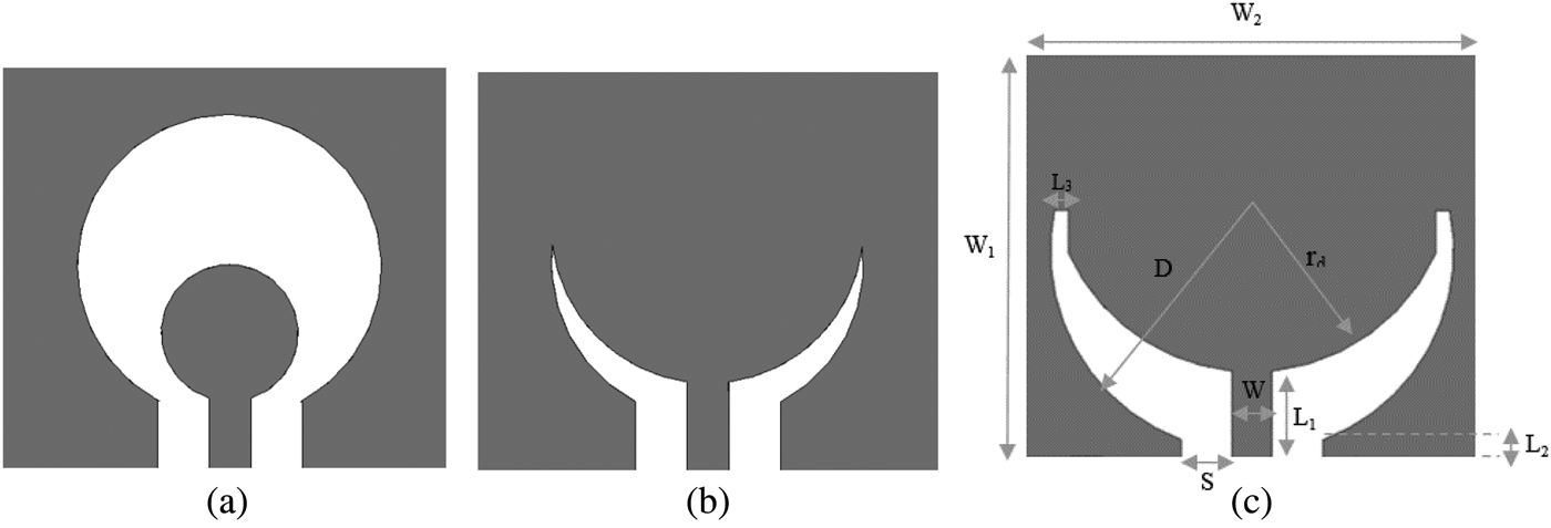
The next step is designing a UWB propagator. A suitable impedance matching over wide range of frequency, by keeping the reflection coefficient S 11 below −10 dB, is a challenge in the context of the UWB antenna design. CPW-fed circular slot antennas with a metallic patch inside the slot have the advantages of suitable gain, high bandwidth, and less sensitivity to manufacturing tolerances than patch antennas [Reference Kumar and Shanmuganantham4]. Figure 2(a) shows the circular slot fed by a circular patch through a CPW line. The diameter of circular aperture D determines lower resonant frequency; and radius of inner conductor r d sets impedance matching in the desired frequency ranges [Reference Kumar and Shanmuganantham4, Reference Denidni and Habib27]. We kept antenna dimensions 8 × 9 mm2. In [Reference Kumar and Shanmuganantham4], it has been shown that the aperture and inner conductor diameters are proportional to the wavelength. In this desired frequency range 2–11 GHz, D must be set bigger than antenna dimensions; therefore, it seems that the choice of circular slot antenna is useless. By increasing inner conductor radius and merging inner conductor with outer conductor, we achieved a novel moon-shaped hybrid-patch-slot antenna. Figure 2(b) is illustrating the proposed antennas.
Geometric structure of propagator (a) CPW-fed circular antenna, (b) the proposed antenna, and (c) optimized moon-shaped slot antenna.

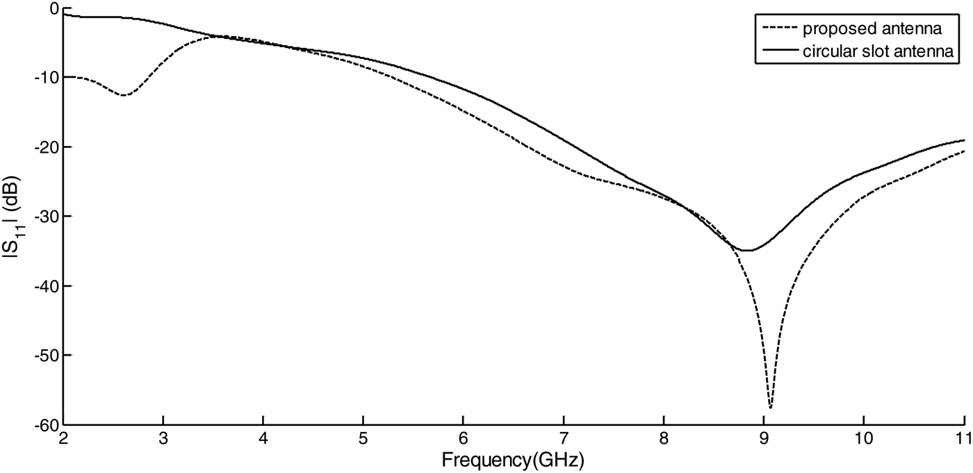
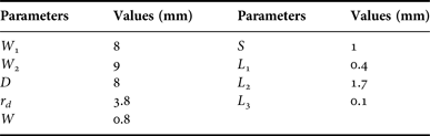
Figure 3 shows a comparison between the proposed antenna and circular antenna in terms of reflection coefficient. It seems that the proposed antenna has the potential of providing acceptable impedance matching in the desired frequency range. Consequently the propagator dimensions are optimized to achieve the bandwidth of interest. Figure 2(c) shows the optimized geometric parameters of UWB moon-shaped implantable antenna. In Table 1, equivalent optimized values of geometric parameters are reported.
Simulated reflection coefficient for circular slot antenna and the proposed antenna.

Geometric parameter values of optimized antenna.

III. RESULTS AND DISCUSSION
In this section, we consider different aspects of the proposed antenna performances. The maximum input power is evaluated to meet the SAR and EIRP limitations.
A) Reflection coefficient and near-field characteristics
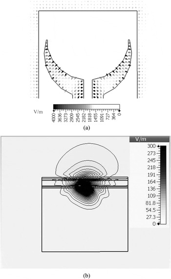
The proposed antenna is a kind of CPW-fed wide slot antennas introduced in [Reference Garg, Bhartia, Bahl and Ittipiboon16]. In these types of antennas, the resonant length of a slot is about half a guide wavelength in contrast to one guide wavelength for loop slots. As a result, the proposed slot antenna with its suitable curvature produces required resonance wavelength in the defined frequency range. The electric feed lines of CPW gaps excite the slots. As shown in Fig. 4(a), both components of electric field existed in the slots are responsible for producing the magnetic surface current, which is the source of radiations.
Near-field electric intensity of the implantable antenna. (a) Top view. (b) Side view.

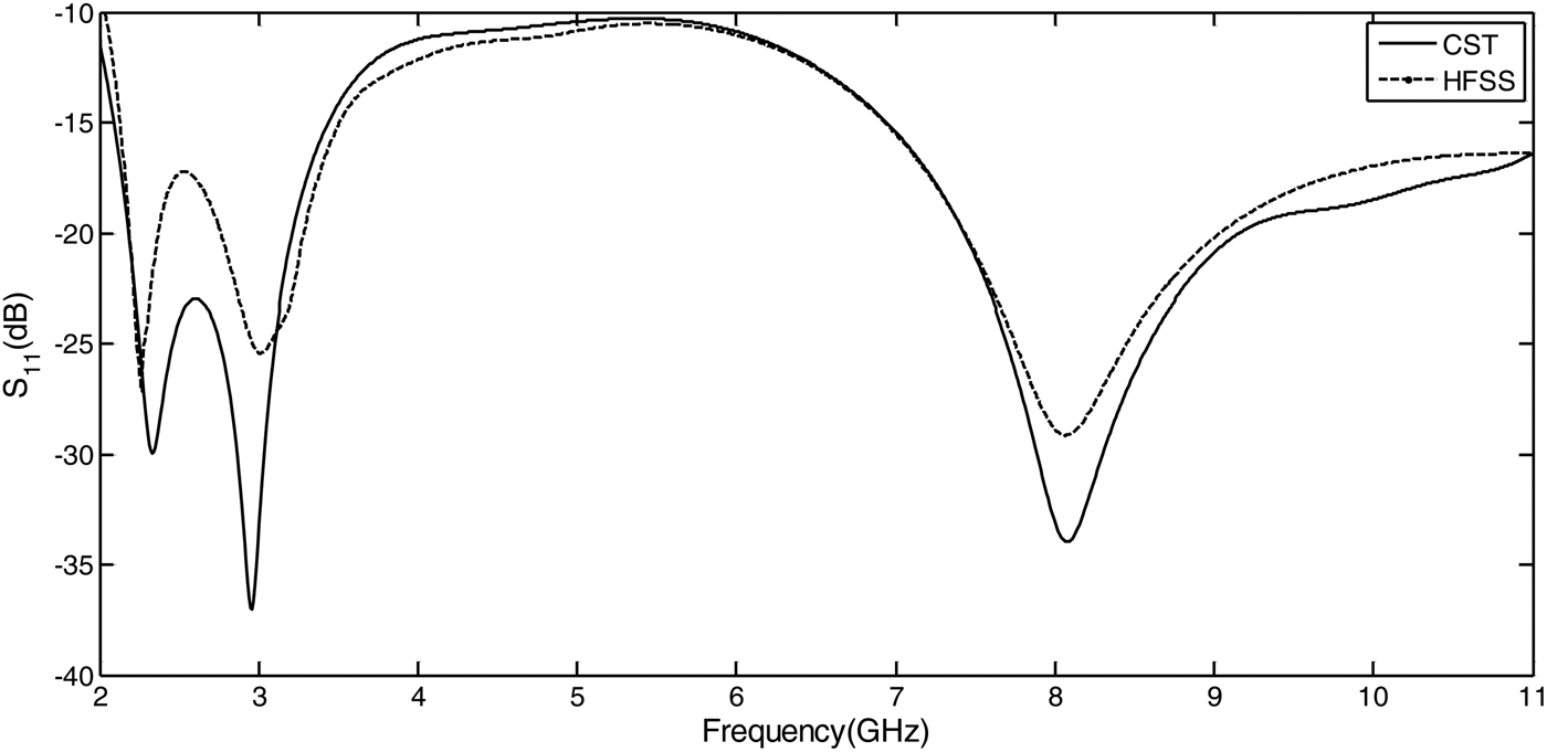
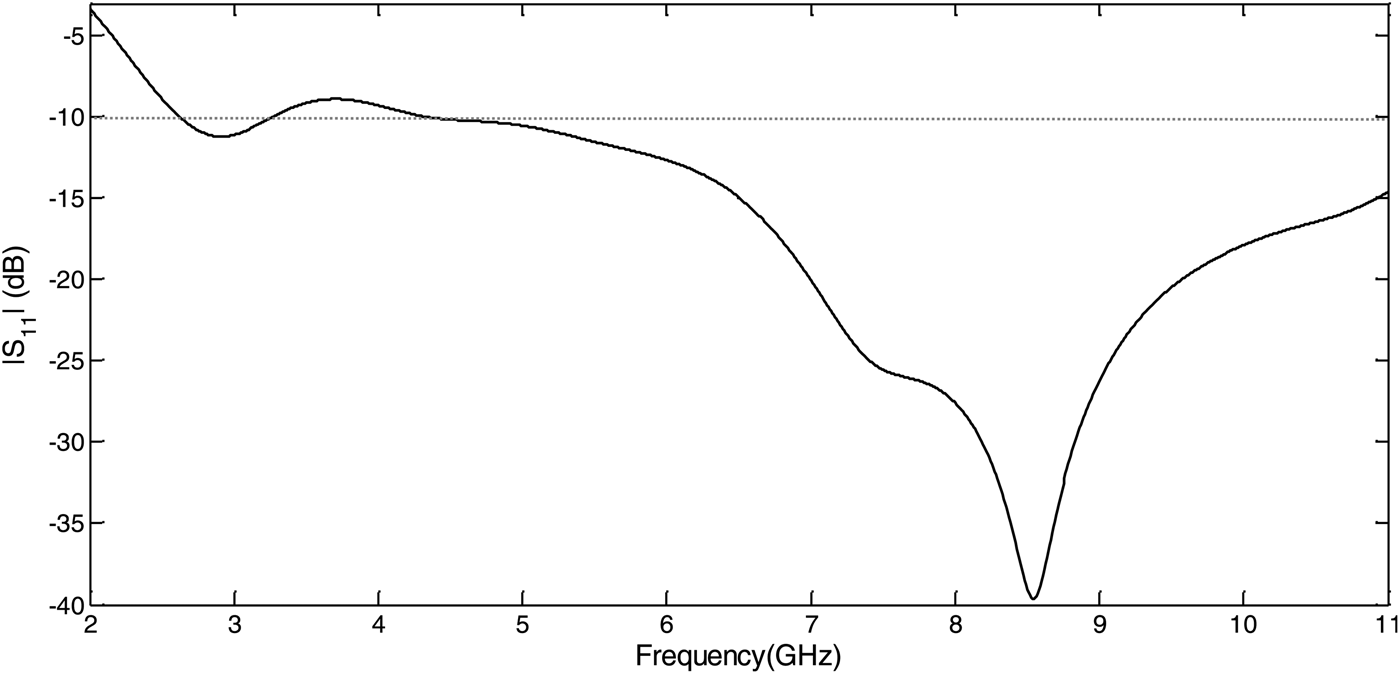
The side view of electrical intensity is presented in Fig. 4(b). More power is absorbed in dura, CSF, and brain tissues due to their higher dielectric constants and thicknesses. Therefore, they produce higher SAR as well. Figure 5 illustrates the reflection coefficients of optimized antenna. S 11 parameter is below −10 dB in all desired frequency range and the desired impedance matching is obtained. The validation of the result was done with HFSS software as shown in Fig. 5, as well. The negligible differences are due to different mechanisms of numerical solution of two softwares.
Simulated S 11 for optimized antenna structure.

Two main resonance frequencies are seen at 2.95 and 8 GHz. In these two frequencies, according to average dielectric constant of antenna environment, the effective wavelengths are about 20.262 and 7.751 mm, respectively. The physical length of the slot antenna is 10.8 mm, which is almost half wavelength and one wavelength at 2.95 and 8 GHz. These lengths are defined as resonance length for simple CPW-fed slot antenna according to Garg et al. [Reference Garg, Bhartia, Bahl and Ittipiboon16]; therefore, the required resonance length in the limited space has been achieved by bending the slot and designing the proposed moon-shaped slot antenna.
B) Far-field characteristics of the antenna
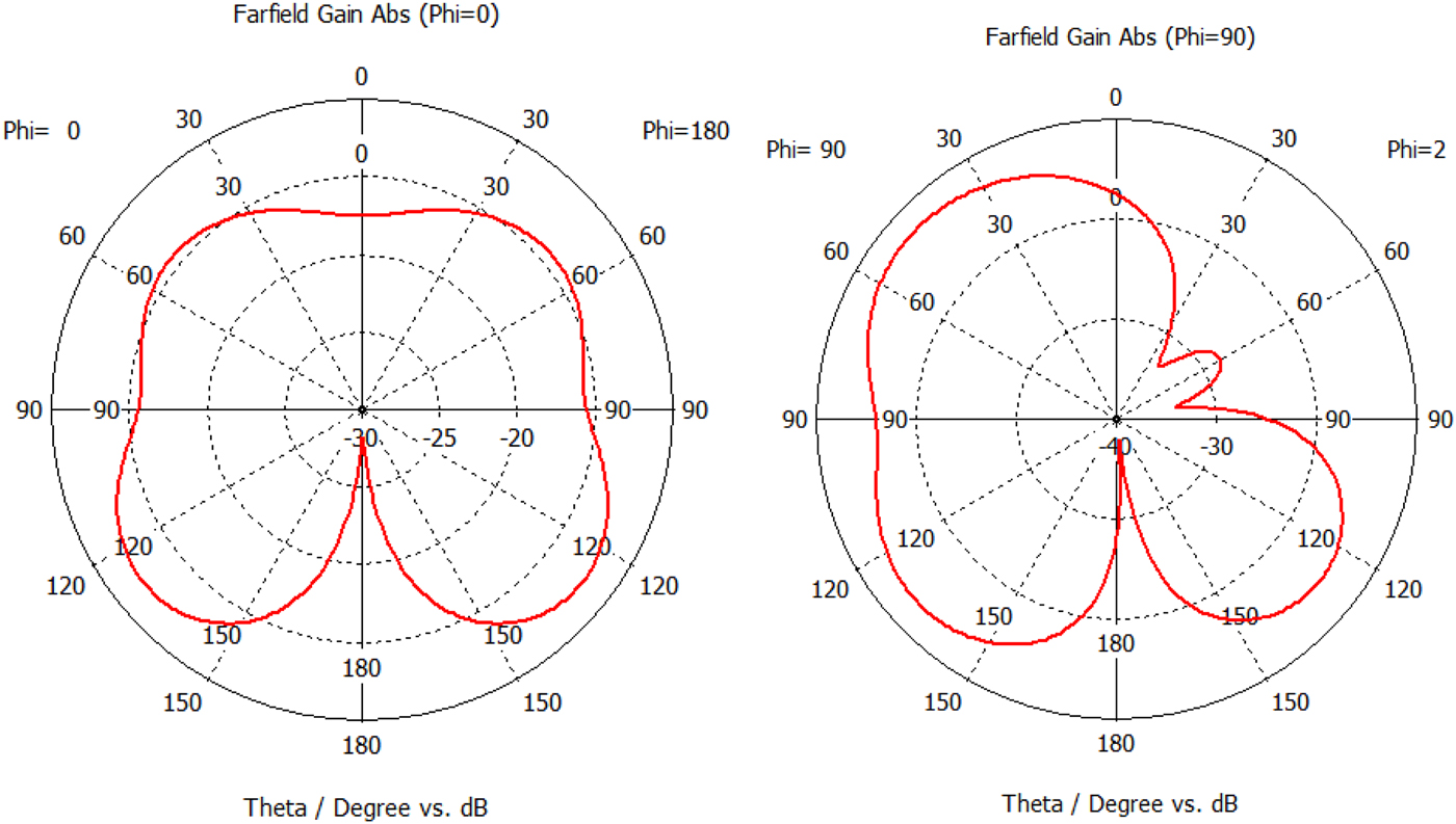
The radiation pattern of the proposed structure is shown in Fig. 6. The tissues in the head are responsible for blocking and absorbing the radiation from the antennas, so that the radiation patterns become directional and more directive in the broadside direction, i.e. from inside to the outside of the head.
Radiation pattern for plane Ф = 0, Ф = 90 versus Ө for frequency 6.5 GHz.

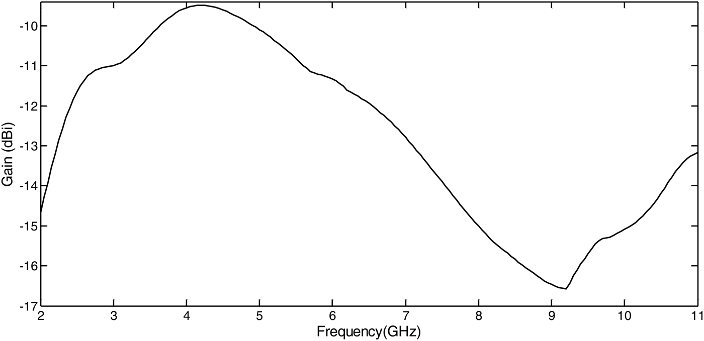
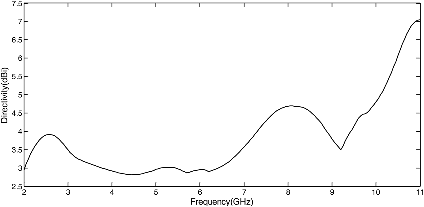
The maximum of 3D far-field realized gain pattern versus frequency is shown in Fig. 7. The maximum gain of antenna decreases due to increased losses of biological tissues with increasing frequency. Some misbehavior seen in the figure is because of tissues finite dimensions surrounding the antenna. In Fig. 8, antenna directivity is in proper range, i.e. more than 0 dB for short-range UWB communication. The directivity of antenna is independent of surrounding environment and determined with respect to antenna structures.
Simulated maximum gain of the antenna versus frequency.

Simulated maximum directivity of the antenna versus frequency.

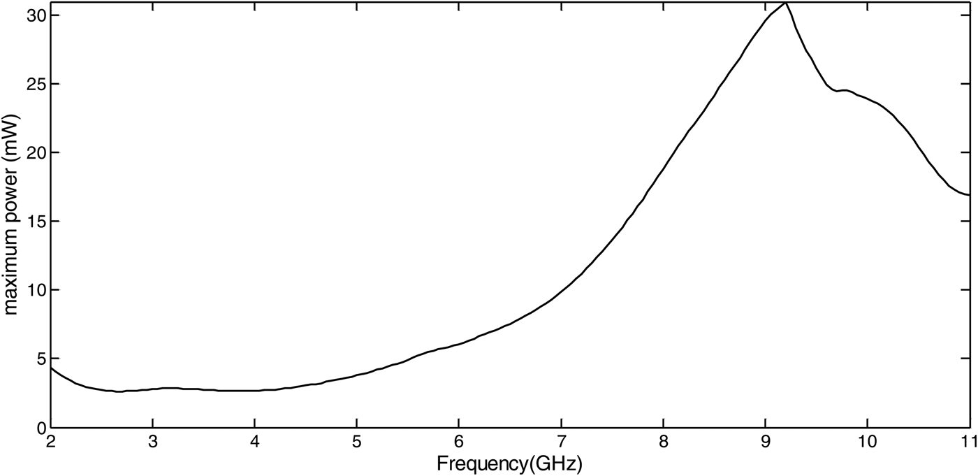
As mentioned before, the FCC mask for the EIRP in the UWB frequency range is limited to −41.3 dBm/MHz. It means that the maximum power of transmitter (P t ) plus maximum antenna gain (G t ) should not exceed more than this value. By using equation (1) and gain obtained, the maximum power of the proposed antenna versus frequency is evaluated and shown in Fig. 9. The minimum P t is 2.62 mW, which is considered so that the maximum power of the antenna fulfills EIRP limitation in whole UWB frequency range.
 $$P_t + G_t = - 41.3\left[ {\displaystyle{{{\rm dB}} \over {{\rm MHz}}}} \right] + 10\,{\rm log}_{10} ({\rm frequency[MHz}]).$$
Propagator maximum power versus frequency according to the FCC regulation for EIRP.

C) Specific absorption rate (SAR)
Studies have shown that a 1 °C temperature rising could be harmful to the human body. One dosimetry parameter, which is related to temperature is SAR [Reference Thotahewa, Redoute and Yuce6]. SAR describes the absorbed electromagnetic energy in biological tissues and can be calculated as follows [Reference Kiourti and Nikita1, Reference Nikita2]:
 $${\rm SAR} = \displaystyle{1 \over 2}\displaystyle{\sigma \over \rho} \vert E \vert ^2, $$
where the intensity of electric field inside the body is |E|, the conductivity is σ and the mass density of the human tissues is ρ. Issues related to patient safety restricted the maximum average SAR over any 1 g of tissues to <1.6 W/kg according to IEEE C95.1–1999 standard [Reference Kiourti and Nikita1, Reference Nikita2, Reference Bahrami, Mirbozorgi, Ameli, Rusch and Gosselin7]. Based on this standard, the allowable power incident on the antenna should be restricted.
Figure 10 shows the average SAR versus frequency. To reach standard limitation, 2.5 mW net input power is considered. Sending more power can damage the biological tissues. This figure shows that most of the radiated power is absorbed by the brain. Maximum field intensity shows the maximum SAR around that area.
Simulated average SAR in different tissues with the maximum input power of 2.5 mW.

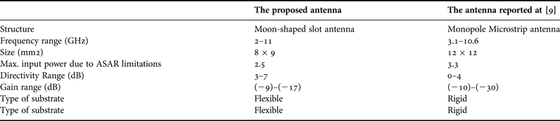
Table 2 shows a comparison between the proposed antenna and the antenna reported at [Reference Bahrami, Gosselin and Rusch9]. The proposed antenna occupies smaller space and because of that, some degradation in gain and allowable input power are expected. On the other hand, the proposed antenna has a larger bandwidth with more functionalities.
A comparison between the proposed antenna and the antenna reported at [Reference Bahrami, Gosselin and Rusch9].

D) Bending effect
With respect to the physical mean curvature of matured human head and the size of the proposed antenna, we considered up to 6° of bending. As seen in Fig. 11, reflection coefficient at lower frequency exceeds −10. The maximum allowable net power drops to 1.9 mW. Antenna gain decreases in part of frequency range (e.g. −12.57 dB at 6.5 GHz). Despite some impairments of bending effect, the bended antenna performances are still acceptable.
Simulated reflection coefficient of the antenna under 6° bending.

E) Antenna fabrication
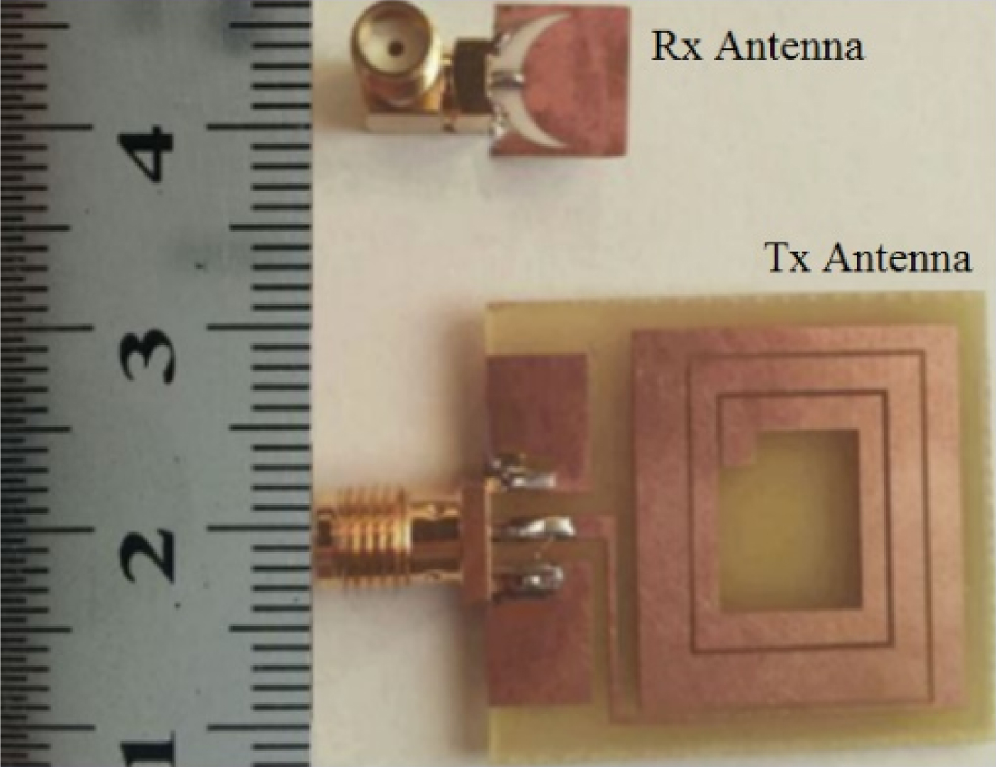
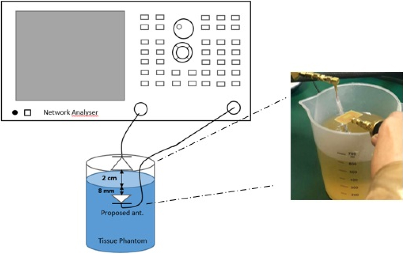
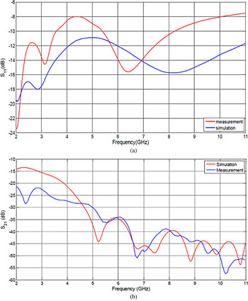
The proposed antenna is fabricated on RO4003C substrate having relative permittivity of 3.48 and height of 8 mils and is shown in Fig. 12. To be able to measure the power absorbed by the tissue, we have designed and modified another antenna playing the role of receiving antenna, while the proposed antenna is the transmitter. The receiver antenna is modified version of dual polarized receiver antenna introduced in [Reference Bahrami, Mirbozorgi, Ameli, Rusch and Gosselin7] based on our scenario. Figure 13 shows measurement setup used for measuring S parameters. The phantom modeling the head is made by a mixture of sugar and distilled water. The mass fractions are respectively 40 and 60%. The two antennas are connected to the two ports of the 8753ES Agilent Network Analyzer. The comparison of measured and simulated scattering coefficients is shown in Fig. 14. Although there are some differences, overall behavior is similar. It is noticeable that |S 21|2 is the relative power absorbed by the tissue.
Fabricated T x and R x (moon-shaped) antennas.

S parameter measurement setup.

Measured versus simulated: (a) reflection coefficient, (b) transmission coefficient.

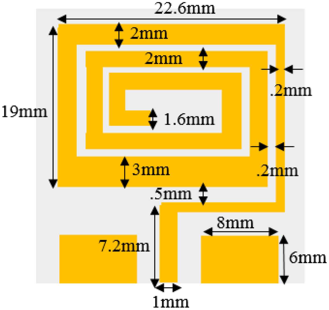
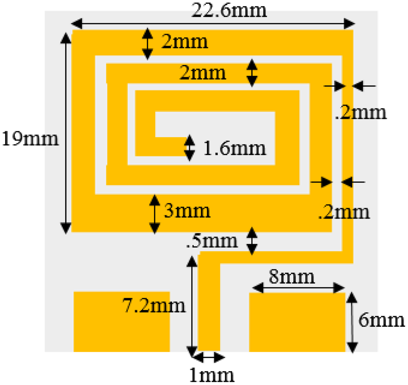
The geometrical parameters of the receiving antenna are presented in Fig. 15. This antenna is fabricated on 26.3 × 30 × 1.6 mm3 FR4 substrate.
Geometrical parameters of R x antenna.
IV. CONCLUSION
UWB technologies are a good candidate for neural recording systems by introducing higher data bit rate to transmit data. We designed a UWB moon-shaped implantable slot antenna to cover 2–11 GHz frequency range for forward and backward telemetry. Maximum gain and directivity of the proposed antenna has been in suitable range for biomedical implants in this frequency range and it keeps its performance acceptable under 6° of bending. Finally, to obey the EIRP and SAR restriction for UWB antennas, maximum input power of the transmitter was fixed to be 2.5 mW. The proposed antenna has been fabricated and tested using a phantom. The results show a good match between simulation and measurement.
 Roshanak Elyassi received her B.Sc. in Electrical Communication Engineering from Tehran University, Tehran, Iran in 2013, and the M.Sc. in Electromagnetics Fields and Waves from Tehran Polytechnic University, Tehran, Iran in 2016. Her research field include bio-Electromagnetics and antenna.
 Gholamreza Moradi received his B.Sc. in Electrical Communication Engineering from Tehran University, Tehran, Iran in 1989, and the M.Sc. in the same field from Iran University of Science and Technology in 1993. Then he received his Ph.D. degree in Electrical Engineering from Tehran Polytechnic University, Tehran, Iran in 2002. His research areas include applied and numerical Electromagnetics, Microwave measurement and antenna. He has published more than seventy journal papers and has authored/co-authored seven books in his major. He is currently an Associate Professor with the Electrical Engineering Department, Amirkabir University of Technology (Tehran Polytechnic), Tehran, Iran.