1. Introduction
With the development of space technology, space manipulator has been used more and more widely [Reference Ding, Wang, Wang and Xu1, Reference Papadopoulos, Aghili, Ma and Lampariello2, Reference Zong and Emami3]. Due to space microgravity, there are strong couplings between the base and the arm. The reaction forces and torques onto the base caused by the space manipulator lead to the translation motions and rotations of the base, which in turn affect the manipulation performances of the arm. In order to guarantee better navigation and communication signal, as well as ensure the solar panels work, certain attitudes of the base need to be kept. Attitudes of the base can usually be controlled by the active attitude control system (ACS) [Reference Seddaoui and Saaj4, Reference Jayakody, Shi, Katupitiya and Kinkaid5, Reference Seddaoui and Saaj6, Reference Rybus7]. However, the ACS sometimes needs to be shut down to avoid collisions between the gripper of the manipulator and the handle of the target during the sudden firing of the thrusters, as well as to conserve fuel. So other techniques are required.
Dubowskys et al. [Reference Dubowsky and Papadopoulos8, Reference Dubowsky and Torres9] proposed an enhanced disturbance map (EDM) based joint motion planning strategy to reduce the attitude disturbance of the base caused by the manipulator motion. By a fixed-attitude-restrict Jacobian matrix (FARJM) based technique, Nenchev et al. [Reference Nenchev, Umetani and Yoshida10] conducted zero-disturbance planning of a space manipulator. Furthermore, Yoshida et al. [Reference Yoshida, Hashizume and Abiko11] addressed the redundant degree of freedom of the space manipulator and realized zero reaction maneuver (ZRM) by introducing a combined matrix [Reference Yoshida12, Reference Fukazu, Hara, Kanamiya and Sato13]. To the dynamic uncertain system, Nguyen Huynh et al. [Reference Nguyen Huynh and Sharf14] investigated the base attitude zero disturbance while the arms moved. And Xu et al. [Reference Xu, Wang, Zhang and Yang15] studied a reactionless adaptive kinematics controller to ensure the base’s attitude controlled and the end-effector to track the desired trajectory. Zong et al. [Reference Zong, Emami, Luo and Luo16] presented a new dynamic formulation as well as control scheme for space manipulators to assure the end-effector to track a desired trajectory and to minimize the base disturbances caused by the arm movements, in which joint controllers were designed without solving for the inverse kinematics and computing the derivative of the generalized Jacobian matrix.
Sliding mode control can be applied to control space manipulators [Reference Ding, Wang and Zheng17, Reference Nasiri, Kiong Nguang and Swain18, Reference Alwi and Edwards19], in which there are structured uncertainty (and) or unstructured uncertainty [Reference Tran and Kang20]. Moreover, diverse sliding surfaces were designed [Reference Ding, Wang and Zheng17, Reference Su and Zong21, Reference Al-Ghanimi, Man and Zheng22, Reference Yu23], and different sliding mode controllers (SMC) were proposed. Bayat [Reference Bayat24] combined nonlinear terminal sliding mode control (TSMC) and linear model predictive control (MPC) in a compound double layer structure to deal with the robust optimal three-axis attitude tracking problem of spacecraft. Shao et al. [Reference Shao, Sun, Xue and Li25] proposed a nonsingular terminal sliding mode controller (NTSMC) for free-floating space manipulators (FFSMs) to improve the transient performance and reduce unexpected base motion in the presence of disturbance. Zhu et al. [Reference Zhu, Qiao and Guo26] investigated the precise and fast trajectory tracking controller for the free-flying space manipulator, after capturing a space target with uncertain mass, and proposed a novel adaptive sliding mode disturbance observer (ASMDO) which assured the estimation error of ASMDO stabilized in finite-time with the bound of the derivative of system uncertainty unknown. Since the time delay estimation (TDE) technique was proposed, more attention is paid to the TDE-based controller (TDEC) for its low dependence on the dynamics model [Reference Wang, Chen, Gu and Li27, Reference Liang, Wan, Zhang, Kong, Xin and Yi28, Reference Chang and Park29, Reference Wang, Luo, Gu and Li30]. However, without taking the compensation of the TDE error into account, there is serious chattering in SMC [Reference Liang, Wan, Zhang, Kong, Xin and Yi28]. Lee [Reference Lee, Yoo, Park, Park, Lee, Gweon and Chang31] et al. made an experimental study on time delay control of actuation system of tilt rotor unmanned aerial vehicle. TDE techniques were studied and SMC based on TDE of terrestrial manipulators were proposed [Reference Brahmi, Driscoll, Laraki and Brahmi32, Reference Wang, Fei, Jiang and Chen33]. Jung et al. [Reference Jung and Lee34] demonstrated the structural equivalence between a nonlinear disturbance observer and a time-delay controller (TDC) under the non-model-based control framework of terrestrial manipulators. Zhang [Reference Zhang, Yu and Chen35] et al. addressed an adaptive fuzzy SMC to control a free-flying space manipulator. Liang [Reference Liang36] studied a fuzzy wavelet neural network sliding mode controller for a free-flying flexible joint double-arm space robot based on TDE. And Xie et al. [Reference Xie, Sun and Wu37] presented a new adaptive small chattering sliding mode control (SCSMC) scheme that uses reinforcement learning (RL) and time-delay estimation (TDE) for the motion control of free-floating space robotic manipulators (FSRM) subject to model uncertainty and external disturbance.
The motion planning strategies [Reference Rybus7, Reference Dubowsky and Papadopoulos8, Reference Dubowsky and Torres9, Reference Nenchev, Umetani and Yoshida10, Reference Yoshida, Hashizume and Abiko11, Reference Yoshida12, Reference Fukazu, Hara, Kanamiya and Sato13, Reference Nguyen Huynh and Sharf14, Reference Xu, Wang, Zhang and Yang15, Reference Zong, Emami, Luo and Luo16] were mainly devoted to general operations of space manipulations, which cannot apply to cases of a space manipulator’s pregrasping a spinning target. Furthermore, there are no limits and restrictions of the joint angular accelerations, which need to be considered to accommodate the actual working situations. And in the TDE-based controllers [Reference Lee, Yoo, Park, Park, Lee, Gweon and Chang31, Reference Brahmi, Driscoll, Laraki and Brahmi32, Reference Wang, Fei, Jiang and Chen33, Reference Jung and Lee34], a fixed inertial matrix estimate is adopted all the time, which may lead to degradation of the controller for a time-varying task. In this work, RNS planning and control of a planar three-link space manipulator’s pregrasping a spinning target are studied. First, the Lagrange dynamic model of the manipulator was established. Second, the RNS motion planning algorithm was derived, and the vector norm constraint algorithm of RNS planning was addressed to ensure certain joint angular acceleration constraints were satisfied. Furthermore, an augmented adaptive sliding mode control algorithm based on TDE was proposed. This algorithm estimated the unknowns by TDE technology, in which accurate and complete dynamics were not required. An adaptive TDE was introduced to decrease the estimation errors and avoid serious chattering. Finally, numerical simulations were carried out to verify the effectiveness of the proposed RNS planning and control algorithm.
2. Dynamic modeling of space manipulators
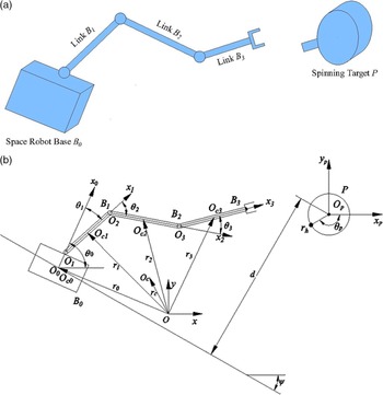
A planar three-link space manipulator and a spinning target are shown in Fig. 1. The space manipulator consists of a free-floating rigid base B
0 (chaser) and rigid bars B
1, B
2, B
3. P is the target to be captured.
 $Oxy$
is the inertial coordinate frame of the system. And the base moves along its trajectory with a velocity
 $\textbf{v}$
. It is assumed that the mass center of the whole system and that of the base satellite coincide for any configuration of the manipulator [Reference Zong, Emami, Luo and Electron38]. Due to the large radius of curvature of the trajectory, the trajectory in a short period can be approximately regarded as a straight line. The target is a cylindrical object revolving around its mass center with angular velocity
 ${\dot \theta _p}$
, and the distance between its handle and its mass center is r
h. The trajectory of the base is inclined at an angle
 $\psi $
relative to the x axis, and the distance between the mass center of the target and the base’s trajectory is d. At the point of interception, the relative velocity between the manipulator end-effector and the handle of the target is
 $\Delta \textbf{v}$
.
 ${O_i}{x_i}{y_i}$
is the local coordinate frame of
 ${B_i}(i = 0,1,2,3)$
. O
0 is coincident with the mass center O
c0 of B
0,
 ${O_{ci}}$
is the mass center of
 ${B_i}(i = 0,1,2,3)$
,
 ${O_i}(i = 1,2,3)$
is the rotational center of the revolute joint between
 ${B_{i - 1}}$
and
 ${B_i}(i = 0,1,2,3)$
,
 ${x_i}(i = 1,2,3)$
is the symmetry axis of B
i
, respectively. Other symbols are defined as follows:
-
e i Unit vector along the x i axis;
-
l 0 Distance between points O 0 and O 1;
-
li Length of B i (i = 1,2,3) along the x i axis;
-
bi Distance between point
 ${O_i}(i = 1,2,3)$
and the mass center O
Ci
(i = 1,2,3);
-
m i Mass of B i (i = 0,1,2,3);
-
Ji Inertial moment of B i with respect to its mass center O Ci (i = 0,1,2,3);
-
O c Mass center of the system;
-
θ 0 Attitude angle of x 0 axis relative to x axis;
-
θ i Joint angles of B i (i = 1,2,3);
-
r i Position vector of the mass center O Ci of B i (i = 0,1,2,3) in (O-xy) frame,
${r_i} = {[{x_i}\quad {y_i}]^{\textrm{T}}}$
; -
T
i
The kinetic energy of B
i
(i = 0,1,2,3)
-
$\dot{( \ )}$
The first time derivative of
$(\ )$
;
-
$\ddot{( \ )}$
The second time derivative of
$(\ )$
;
-
$\hat{(\ )}$
The estimate of
$(\ )$
;
-
$\left[\left(\,\,\,\right)\right]$
The allowable value of
$(\,)$
.


 T
i
The kinetic energy of B
i
(i = 0,1,2,3)


From Fig. 1, r i (i = 1,2,3) are
 \begin{equation}\textbf{r}_i=\textbf{r}_0+\sum\limits_{j = 0}^{i - 1} {{l_j\textbf{e}_j}}+b_i\textbf{e}_i\end{equation}
Differentiating Eq. (1) with respect to time t,
 ${\dot{\textbf{r}}_i}$
(i = 1,2,3) are
 \begin{equation}\dot{\textbf{r}}_i=\dot{\textbf{r}}_0+\sum\limits_{j = 0}^{i - 1} {{l_j\dot{\textbf{e}}_j}}+b_i\dot{\textbf{e}}_i\end{equation}
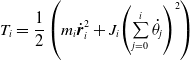
Then the manipulator system’s total kinetic energy T is
 \begin{align}T = \sum\limits_{i = 0}^3 {{T_i}} \end{align}
where
 ${T_i} = \dfrac{1}{2}\left( {{m_i}\dot{\textbf{r}}_i^{\rm{2}} + {J_i}{{\left( {\sum\limits_{j = 0}^i {{{\dot \theta }_j}} } \right)}^2}} \right)$
.
A free-floating space manipulator and a spinning target.

The microgravity is ignored, and the potential energy of the system V is 0. Then the system’s Lagrangian L = T-V= T and the Euler–Lagrange dynamic equations of the space manipulator are derived as [Reference Song39]
 \begin{equation}\textbf{D}(\textbf{q})\ddot{\textbf{q}}+\textbf{H}(\textbf{q},\dot{\textbf{q}})\dot{\textbf{q}}=\boldsymbol{\tau}\end{equation}
where
 $\textbf{q} = [\begin{array}{c@{\quad}c@{\quad}c@{\quad}c@{\quad}c@{\quad}c} {{x_0}} & {{y_0}} & {}{{\theta _0}} & {{\theta _1}} & {}{{\theta _2}} & {{\theta _3}} \end{array} ]^{\rm{T}}$
is the generalized coordinates,
 $\textbf{D}(\textbf{q})\in\textbf{R}^{6\times6}$
denotes the symmetric inertial matrix,
 $\textbf{H}(\textbf{q},\dot{\textbf{q}})\in\textbf{R}^{6\times6}$
is the Coriolis/centrifugal matrix,
 ${\boldsymbol{\tau}} = {\left[{\textbf{0}}\;\;\;{\boldsymbol{\tau}}_l^{\textrm{T}}\right]^{\textrm{T}}} \in {{\textbf{R}}^{6 \times 1}}$
,
 ${{\boldsymbol{\tau}}_l} = {[{\tau _1}\;\;\;{\tau _2}\;\;\;{\tau _3}]^{\textrm{T}}} \in {{\textbf{R}}^{3 \times 1}}$
,
 ${{\tau }_i}(i = 1,2,3)$
is the input torque of joint i.
3. RNS motion planning of space manipulators
3.1. RNS motion planning algorithm
By partitioned matrix, Eq. (4) is rewritten as
 \begin{align}\left[\begin{array}{c@{\quad}c} {{{\textbf{D}}_{bb}}} & {}{{{\textbf{D}}_{bl}}} \\[4pt] {{{\textbf{D}}_{lb}}} & {}{{{\textbf{D}}_{ll}}}\end{array} \right] \left[ \begin{array}{c} {{{\ddot{\textbf{q}}}_b}} \\[4pt] {{{\ddot{\textbf{q}}}_l}} \end{array} \right] + \left[ \begin{array}{c} {{{\textbf{H}}_b}} \\[4pt] {{{\textbf{H}}_l}} \end{array} \right] \left[ \begin{array}{c} {{{{\dot{\textbf{q}}}}_b}} \\[4pt] {{{{\dot{\textbf{q}}}}_l}} \end{array} \right] = \left[ \begin{array}{c} \textbf{0} \\[4pt] {{\boldsymbol{\tau} _l}} \end{array} \right]\end{align}
where
 $\textbf{D}_{bb}\in\textbf{R}^{3\times3}$
is the base inertia matrix,
 $\textbf{D}_{ll}\in\textbf{R}^{3\times3}$
is the arm inertial matrix,
 $\textbf{D}_{bl}\in\textbf{R}^{3\times3}$
is the base-arm coupling inertia matrix,
 $\textbf{q}_{b} = {[ {{x_0}}\quad {}{{y_0}}\quad {}{{\theta _0}} ]^{\textrm{T}}}$
,
 $\textbf{q}_{l} = {[{{\theta _{\rm{1}}}} \quad {}{{\theta _{\rm{2}}}}\quad {}{{\theta _{\rm{3}}}} ]^{\textrm{T}}}$
.
Integrating the first row of Eq. (5), the system’s linear momentum P and angular momentum L [Reference Yu, Guo and Zhang40] are
 \begin{align}\left(\begin{array}{c}{\textbf{P}}\\[3pt]{\textbf{L}}\end{array}\right) = \int \textbf{0}dt = {{\textbf{D}}_{bb}}{{\dot{\textbf{q}}}_b} + {{\textbf{D}}_{bl}}{{\dot{\textbf{q}}}_l} = const\end{align}
where
 ${{\textbf{D}}_{bb}}{{\dot{\textbf{q}}}_b}$
is the base momentum,
 ${{\textbf{D}}_{bl}}{{\dot{\textbf{q}}}_l}$
is the coupling momentum generated by the arm motion. Introduce
 ${\textbf{L}_l} = {{\textbf{D}}_{bl}}{{\dot{\textbf{q}}}_l}$
and the derivative of
 ${\textbf{L}_l}$
is
 \begin{equation}\dot{{\textbf{L}_l}}={\textbf{F}_l}={{\textbf{D}}_{bl}}{{\ddot{\textbf{q}}}_l} + {{\dot{\textbf{D}}}_{bl}}{{\dot{\textbf{q}}}_l}\end{equation}
where
 ${\textbf{F}_l}$
is the reaction forces induced on the base from the motion of the arm.
When coupling momentum is constant,
 ${{\textbf{F}_l}} \equiv {\textbf{0}}$
. Then the arm’s motion leads to no reaction force or torque to the base. When the number of the degree of freedom of the manipulator is greater than that of the base coordinates, the manipulator joint rates satisfy [Reference Yu, Guo and Zhang40]
 \begin{align}{{{{\dot{\textbf{q}}_l}}}} = {\textbf{D}}_{bl}^ + {{\textbf{L}_l}} + \left( {\textbf{I}- {\textbf{D}}_{bl}^ + {\textbf{D}_{bl}}} \right){\boldsymbol\xi} \end{align}
where
 ${(\,)^ + }$
is the pseudo-inverse of
 $(\,)$
,
 $\textbf{I}\in\textbf{R}^{3\times3}$
represents the identity matrix,
 $({\textbf{I}} - {\textbf{D}}_{bl}^ + {{\textbf{D}}_{bl}})$
is the mapping onto the null space of
 ${\textbf{D}_{bl}}$
, and
 ${\boldsymbol{\xi }} \in {{\textbf{R}}^{3 \times 1}}$
represents an arbitrary vector. This inertial null space is called the “zero reaction space.” When the coupling momentum
 ${\textbf{L}_l} = {\textbf{0}}$
, Eq. (9) is obtained
 \begin{align}{\left( {{{{\dot{\textbf{q}}}}_l}} \right)_{RNS}} = \left( {{\textbf{I}} - {\textbf{D}}_{bl}^ + {{\textbf{D}}_{bl}}} \right)\boldsymbol\xi \end{align}
The base’s attitude is merely considered and the modified coupling inertial matrix
 ${{{\tilde{\textbf{D}}}}_{bl}} = [{D}_{34}\ \ {}{D}_{35}\ \ {}{D}_{36} ]$
[Reference Brahmi, Driscoll, Laraki and Brahmi32] is defined, then Eq. (9) is transformed into
 \begin{align}{\left( {{{{\dot{\textbf{q}}}}_l}} \right)_{RNS}} = \left( {\textbf{I} - \tilde {\textbf{D}}_{bl}^ + {\tilde {\textbf{D}}_{bl}}} \right)\boldsymbol\xi \end{align}
The reactionless joint trajectories can be obtained by integrating Eq. (10).
3.2. Vector norm constraint algorithm of RNS planning
 $\boldsymbol\xi $
can be properly chosen to ensure constraints of the joint angular velocities and joint angular accelerations are satisfied. Define
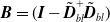 ${\textbf{B}} = (\textbf{I}- {{\tilde{\textbf{D}}}}_{bl}^ + {{{\tilde{\textbf{D}}}}_{bl}})$
and utilize Eq. (10), joint angular velocities
 ${\left( {{{{{{\dot{\textbf{q}}}}}}_l}} \right)_{int}}$
and joint angular accelerations
 ${\left( {{{{{\ddot{\textbf{q}}}}}_l}} \right)_{int}}$
at the interception point are
 \begin{align}\left\{\!\begin{array}{l} \left\| \left( {\dot{\textbf{q}}}_{l} \right)_{int}\right\| = \left\| {{\textbf{B}}}\boldsymbol\xi \right\|\\[5pt]\left\| \left( {\ddot{\textbf{q}}}_{l} \right)_{int}\right\| = \left\| \dfrac{d{\textbf{B}}}{dt} \boldsymbol\xi \right\|\end{array}\right.\end{align}
Extending it to the entire manipulation process, then joint angular velocities
 ${({{\dot{\textbf{q}}}_l})_{RNS}}$
and joint angular accelerations
 ${({\ddot{\textbf{q}}_l})_{RNS}}$
of RNS are
 \begin{align}\left\{\!\begin{array}{l} \left\| \left( {\dot{\textbf{q}}}_{l} \right)_{RNS}\right\| = \left\| {{\textbf{B}}}\boldsymbol\xi \right\|\\[5pt]\left\| \left( {\ddot{\textbf{q}}}_{l} \right)_{RNS}\right\| = \left\| \dfrac{d{\textbf{B}}}{dt} \boldsymbol\xi \right\|\end{array}\right.\end{align}
By Eq. (7), the reaction forces onto the base from the arm are
 \begin{align}{\textbf{F}_{RNS}} = {{\textbf{D}}_{bl}}{\left( {{{{\ddot{\textbf{q}}}}_l}} \right)_{RNS}} + {\dot{\textbf{D}}_{bl}}{\left( {{{{\dot{\textbf{q}}}}_l}} \right)_{RNS}} = \left(\begin{array}{c}{F_x}\\[3pt]{F_y}\\[3pt]{T_z}\end{array}\right)\end{align}
where
 ${F_x}$
and
 ${F_y}$
are reaction forces,
 ${T_z}$
is the corresponding reaction torque.
Substituting
 ${\left( {{{{{{\dot{\textbf{q}}}}}}_l}} \right)_{RNS}} = {\textbf{B}}\boldsymbol{\xi }$
and
 ${\left( {{{{{\ddot{\textbf{q}}}}}_l}} \right)_{RNS}} = \dfrac{d{\textbf{B}}}{dt}\boldsymbol\xi$
into Eq. (13), then combining Eq. (12), Eq. (14) is derived
 \begin{align}\left\{\begin{array}{l} \left\| \left( {\dot{\textbf{q}}}_{l} \right)_{RNS}\right\|_{2} = \left\| {{\textbf{B}}}\boldsymbol\xi \right\|_{2}\\[5pt]\left\| \left( {\ddot{\textbf{q}}}_{l} \right)_{RNS}\right\|_{2} = \left\| \dfrac{d{\textbf{B}}}{dt} \boldsymbol\xi \right\|_{2}\\[9pt]\left\| {{\textbf{F}}}_{RNS}\right\|_{2} = \left\|\left({\textbf{D}}_{bl} \dfrac{d{\textbf{B}}}{dt} + \dot{\textbf{D}}_{bl} {\textbf{B}}\right)\boldsymbol\xi \right\|_{2}\end{array}\right.\end{align}
where
 ${\left\| {} \right\|_2}$
is the Euclidean norm. Then
 \begin{align}\left\{\begin{array}{l} \left\| \left( {\dot{\textbf{q}}}_{l} \right)_{RNS}\right\|_{2}^{2} = \boldsymbol{\xi}^{\textrm{T}}{\textbf{A}}_1 \boldsymbol{\xi}\\[5pt]\left\| \left( {\ddot{\textbf{q}}}_{l} \right)_{RNS}\right\|_{2}^{2} = \boldsymbol{\xi}^{\textrm{T}}{\textbf{A}}_2 \boldsymbol{\xi}\\[9pt]\left\| {{\textbf{F}}}_{RNS}\right\|_{2}^{2} = \boldsymbol{\xi}^{\textrm{T}}{\textbf{A}}_3 \boldsymbol{\xi}\end{array}\right.\end{align}
where
 ${{\textbf{A}}_i} \in {{\textbf{R}}^{3 \times 3}}(i = 1,2,3)$
are obtained by expanding the right side of Eq. (14). Then
 $\boldsymbol{\xi }$
can be calculated by Eq. (15).
The reactionless path of the manipulator can be obtained by integrating Eq. (10) from
 ${t_f}$
to
 ${t_0}$
, in which
 ${t_f}$
is the time of interception and
 ${t_0}$
is the starting time of manipulation. The initial states of the integral are joint angles of the manipulator at the moment of interception, which should be obtained first. This can be obtained by inverse kinematics [Reference Song39].
At the moment of interception, the velocity
 ${\textbf{v}_e}$
of the end-effector should be the same as the velocity
 ${{\textbf{v}}_h}$
of the target handle. In practice,
 $\left\| {{{\textbf{v}}_e} - {{\textbf{v}}_h}} \right\| \le [\Delta v]$
is ensured. The end-effector’s velocity is
 \begin{align}{{\textbf{v}}_e} = {{\textbf{v}}_{O0}} + {{\textbf{v}}_{eO0}}\end{align}
where
 ${{\textbf{v}}_{O0}}$
is the velocity of O
0,
 ${{\textbf{v}}_{eO0}}$
is the relative velocity of the end-effector relative to O
0.
 \begin{align}{{\textbf{v}}_{eO0}} = {\textbf{J}}{{\dot{\textbf{q}}}_\theta }\end{align}
where
 ${{\dot{\textbf{q}}}_\theta } = {[{\dot \theta _0}\quad {\dot \theta _1}\quad {\dot \theta _2}\quad {\dot \theta _3}]^{\textrm{T}}}$
,
 ${\textbf{J}}$
is Jacobian matrix.
 \begin{align}{\textbf{J}} = \left[\begin{array}{l} - {l_0}{s_0} - {l_l}{s_{01}} - {l_2}{s_{012}} - {l_3}{s_{0123}}\quad - {l_1}{s_{01}} - {l_2}{s_{012}} - {l_3}{s_{0123}}\quad - {l_2}{s_{012}} - {l_3}{s_{0123}} \quad - {l_3}{s_{0123}} \\[6pt]{l_0}{c_0} + {l_1}{c_{01}} + {l_2}{c_{012}} + {l_3}{c_{0123}}\qquad {l_1}{c_{01}} + {l_2}{c_{012}} + {l_3}{c_{0123}}\qquad {l_2}{c_{012}} + {l_3}{c_{0123}}\qquad {l_3}{c_{0123}} \end{array}\right]\end{align}
where
 ${s_0} = \sin\! ({\theta _0})$
,
 ${s_{01}} = \sin\! ({\theta _0} + {\theta _1})$
,
 ${s_{012}} = \sin \left({\theta _0} + {\theta _1} + {\theta _2}\right)$
,
 ${s_{0123}} = \sin \left({\theta _0} + {\theta _1} + {\theta _2} + {\theta _3}\right)$
,
 ${c_0} = \cos \left({\theta _0}\right)$
,
 ${c_{01}} = \cos \left({\theta _0} + {\theta _1}\right)$
,
 ${c_{012}} = \cos \left({\theta _0} + {\theta _1} + {\theta _2}\right)$
,
 ${c_{0123}} = \cos \left({\theta _0} + {\theta _1} + {\theta _2} + {\theta _3}\right)$
.
The velocity
 ${{\textbf{v}}_h}$
of the target handle is found from
 \begin{align}{{\textbf{v}}_h} = \left[\begin{array}{c}{{\dot x}_h}\\[4pt] {\dot y}_h \end{array}\right] = \left[\begin{array}{c} {{{\dot x}_P} - {r_h}{{\dot \theta }_P}\sin {\theta _P}}\\[4pt] {{\dot y}_P} + {r_h}{\dot \theta _P}\cos {\theta _P} \end{array} \right]\end{align}
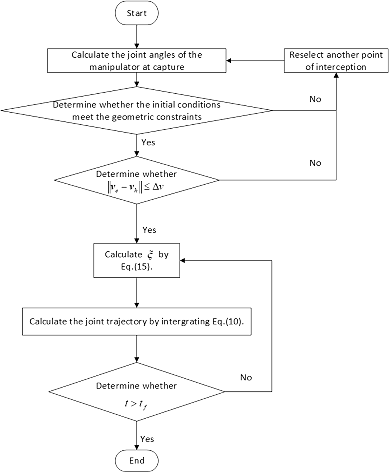
The main steps of the vector norm constraint algorithm of RNS Planning are shown in Fig. 2.
The flow chart of the vector norm constraint algorithm of RNS planning.

4. TDE-based augmented adaptive sliding mode control design
Introduce matrix
 ${{\textbf{D}}_I}{\rm{ = diag(}}{{D}_{I{\rm{1}}}}{\rm{,}} \cdots {{D}_{Ii}}{\rm{,}}{\kern 1pt} \cdots ,{\kern 1pt} {\kern 1pt} {{D}_{I{\rm{6}}}}{\rm{)}}$
, the dynamics Eq. (4) is rewritten as
 \begin{align}\boldsymbol\tau = {{\textbf{D}}_I}{\ddot{\textbf{q}}} + {\textbf{h}}\end{align}
 \begin{align}{\textbf{h}} = \left( {{\textbf{D}}({\textbf{q}}) - {{\textbf{D}}_I}} \right)\ddot{\textbf{q}} + \textbf{H}\left( {{\textbf{q}},{\dot{\textbf{q}}}} \right){\dot{\textbf{q}}}\end{align}
where
 ${{\textbf{D}}_I}$
is the estimate of the inertia matrix
 ${\textbf{D}}$
,
 ${{D}_{Ii}}(i = 1, \cdots ,6)$
are given constants.
Define the augmented output error vector
 \begin{align}{\textbf{e}} = {{\textbf{q}}_d} - {\textbf{q}}\end{align}
 \begin{align}\dot{\textbf{e}} = {{\dot{\textbf{q}}}_d} - {\dot{\textbf{q}}}\end{align}
where
 ${{\textbf{q}}_d} = {\left[ {{x_0}} \quad {}{{y_0}} \quad {}{{\theta _0}}\quad {}{{\textbf{q}}_{ld}^{\textrm{T}}} \right]^{\textrm{T}}}$
and
 ${{{{\dot{\textbf{q}}}}}_d} = {\left[{{{\dot x}_0}} \quad {}{{{\dot y}_0}}\quad {}{{{\dot \theta }_0}} \quad {}{{{{\dot{\textbf{q}}}}}_{ld}^{\textrm{T}}} \right]^{\textrm{T}}}$
are the augmented desired trajectories and the augmented desired velocities,
 ${{\textbf{q}}_{ld}} = {[{{\theta _{1d}}} \quad {}{{{\theta }_{2d}}}\quad {}{{{\theta }_{{\rm{3}}d}}} ]^{\textrm{T}}}$
,
 ${{{{\dot{\textbf{q}}}}}_{ld}} = {[ {{{\dot \theta }_{1d}}}\quad {}{{{{\dot \theta }}_{2d}}} \quad {}{{{{\dot \theta }}_{{\rm{3}}d}}} ]^{\textrm{T}}}$
. Then the augmented output error vector
 ${\textbf{e}}$
is
 \begin{align}{\textbf{e}} = \left[\textbf{0}\quad {\textbf{e}}_l^{\textrm{T}} \right]^{\textrm{T}}\end{align}
where
 ${{\textbf{e}}_l} = {{\textbf{q}}_{ld}} - {{\textbf{q}}_l}$
.
The sliding surface s is chosen as
 \begin{align}{\textbf{s}} = \dot{\textbf{e}} + {\boldsymbol\Lambda _1}{\textbf{e}} + {\boldsymbol\Lambda _2}{\boldsymbol{\rho}}\end{align}
where
 ${{\boldsymbol{\Lambda }}_{\rm{1}}},{{\boldsymbol{\Lambda }}_{\rm{2}}} \in {\textbf{R}^{6 \times 6}}$
are positive definite diagonal matrices,
 ${{\boldsymbol{\Lambda }}_1} = {\rm{diag(}}{{\lambda }_{11}}, \cdots ,{{\lambda }_{1i}}, \cdots ,{{\lambda }_{16}}{\rm{)}}$
,
 ${{\boldsymbol{\Lambda }}_2} = {\rm{diag(}}{{\lambda }_{21}}, \cdots ,{{\lambda }_{2i}}, \cdots ,{{\lambda }_{26}}{\rm{)}}$
,
 ${{\lambda }_{ji}} \gt 0(j = 1,2;\,i = 1, \cdots ,6)$
,
 ${\textbf{s}} = {[ {{{s}_1}}\ \ {} \cdots \ \ {}{{{s}_i}} \ \ {} \cdots\ \ {}{{{s}_6}} ]^{\textrm{T}}}$
,
 ${\boldsymbol{\rho}} = $
 ${[{{{\rho }_1}} \ {} \cdots \ {}{{{\rho }_i}}\ {} \cdots\ {}{{{\rho }_6}} ]^{\textrm{T}}}$
,
 ${{\rho }_i}(i = 1\sim 6)$
are
 \begin{align}{\rho _i} = \left\{\begin{array}{ll} sig{{({e_i})}^{\alpha_{1i}}}, & {}{s_{1i}} = 0 \vee \left({{{s}}_{1i}} \ne {\rm{0}} \wedge |e_i| \geq {\phi _i}\right)\\[5pt]{\eta _{1i}}{e_i} + {\eta _{2i}}f({e_i}), & {}{s_{1i}} \ne 0 \wedge |e_i| \lt {\phi _i}\end{array}\right.\end{align}
 \begin{align}f\!\left( {{e_i}} \right) = \left( 1 + {k_{1i}}\cos \left(\frac{ \pi e_i}{2{\phi _i}} \right) \right)sig{\left( {{e_i}} \right)^{{\alpha _{2i}}}}\end{align}
where
 ${s_{1i}} = {\dot{{e}}_i} + {\lambda _{1i}}{e_i} + {\lambda _{2i}}sig{({e_i})^{{\alpha _{1i}}}}$
,
 $0.5 \lt {\alpha _{{\rm{1}}i}} \lt 1$
,
 $1 \lt {\alpha _{2i}} \lt 2$
,
 ${\phi _i}$
are positive constants,
 $sig{({e_i})^{{\alpha _{ji}}}} = {\left| {{e_i}} \right|^{{\alpha _{ji}}}}{\mathop{\rm sgn}} ({e_i})$
,
 $j = 1,2$
,
 ${\mathop{\rm sgn}} ({e_i})$
,
 ${\eta _{1i}}$
and
 ${\eta _{{\rm{2}}i}}$
are
 \begin{align}{\mathop{\rm sgn}}\! \left( {{e_i}} \right) = \left\{\begin{array}{l@{\quad}l}1, & {e_i} \gt 0\\[3pt]0, & {e_i} = 0\\[3pt]- 1, & {e_i} \lt 0\end{array}\right.\end{align}
 \begin{align}\eta_{1i} = \left( \dfrac{{\alpha _{2i}} - \dfrac{\pi {k_{1i}}}{2} - {\alpha _{1i}}}{{\alpha_{2i}} - \dfrac{\pi {k_{1i}}}{2} - 1} \right){\phi _i}^{{\alpha _{1i}} - 1},{\eta _{2i}}=\left( \frac{{\alpha _{1i}} - 1}{\alpha _{2i} - \dfrac{\pi {k_{1i}}}{2} - 1} \right){\phi _i}^{{\alpha _{1i}} - {\alpha _{2i}}}\end{align}
where
 ${\rm{0}} \le {k_{1i}} \lt \dfrac{2({\alpha _{2i}} - 1)}{\pi}$
.
The first time derivative of
 ${{\rho }_i}$
is
 \begin{align}{\dot \rho _i} = \left\{\begin{array}{ll} {{\alpha _{{\rm{1}}i}}{{\left| {{e_i}} \right|}^{{\alpha _{1i}} - 1}}{\dot{e}_i},} & {}{{s_{1i}} = 0 \vee \left( {{s_{1i}} \ne 0 \wedge \left| {{e_i}} \right| \ge {\phi _i}} \right)}\\[5pt] {{\eta _{1i}}{\dot{e}_i} + F\!\left( {{e_i}} \right),} & {}{{s_{1i}} \ne 0 \wedge \left| {{e_i}} \right| \lt {\phi _i}} \end{array} \right.\end{align}
 \begin{align}F\left( {{e_i}} \right) = {\eta _{2i}}{\alpha _{2i}}\left( {1 + {k_{1i}}{\rm{cos}}\!\left( {{{\pi {e_i}} \over {2{\phi _i}}}} \right)} \right){\left| {{e_i}} \right|^{{\alpha _{2i}} - 1}}{\dot{e}_i} - {\eta _{2i}}{k_{1i}}{\rm{sin}}\!\left( {{{\pi {e_i}} \over {2{\phi _i}}}} \right){sig}{\left( {{e_i}} \right)^{{\alpha _{2i}}}}{{\pi {\dot{e}_i}} \over {2{\phi _i}}}\end{align}
Then the following approaching law
 $\boldsymbol\Delta $
is proposed
 \begin{align}\boldsymbol\Delta = {{\textbf{K}}_1}s - {{\textbf{K}}_2}sig{({\textbf{s}})^\beta }\end{align}
where
 ${{\textbf{K}}_1}$
and
 ${{\textbf{K}}_{\rm{2}}}$
are diagonal matrices,
 ${{\textbf{K}}_1} = {\rm{diag(}}{\mu _{11}}, \cdots ,{\mu _{1i}}, \cdots ,{\mu _{16}}{\rm{)}}$
,
 ${{\textbf{K}}_2} = {\rm{diag(}}{\mu _{21}}, \cdots ,$
 ${\mu _{2i}}, \cdots ,{\mu _{26}}{\rm{)}}$
,
 ${\mu _{ji}} \gt 0(j = 1,2;\, i = 1, \cdots ,6)$
,
 $0 \lt \beta \lt 1$
.
By augmentation approach, an augmented sliding mode controller (controller I) is proposed
 \begin{align}\boldsymbol\tau = {{\textbf{D}_I}}{\boldsymbol{\gamma}} + \hat{\textbf{h}}\left( {{\textbf{q}},{\dot{\textbf{q}}},\ddot{\textbf{q}}} \right) + \left[ {{\boldsymbol\varsigma ^{\textrm{T}}}\quad \bf{0}} \right]\end{align}
 \begin{align}\boldsymbol\gamma = {\ddot{\textbf{q}}_{\rm d}} + {\textbf{w}} + {{\textbf{K}}_1}{\textbf{s}} + {{\textbf{K}}_2}sig{({\textbf{s}})^\beta } + {\textbf{k}}\left| {\textbf{w}} \right|{\mathop{\rm sgn}} ({\textbf{s}})\end{align}
where
 ${{\hat{\textbf{h}}}}$
is the estimate of
 ${\textbf{h}}$
,
 ${\textbf{w}} = {{\boldsymbol{\Lambda }}_1}{\dot{\textbf{e}}} + {{\boldsymbol{\Lambda }}_2}{{\dot{\boldsymbol\rho}}}$
,
 ${\textbf{w}} = {[ {{w_1}} \quad {} \cdots \quad {}{{w_i}} \quad {} \cdots \quad {}{{w_6}} ]^{\textrm{T}}}$
,
 ${\textbf{k}} = diag({k_1}, \cdots,$
 ${k_i}, \cdots ,{k_6})$
,
 ${{k}_i}(i = 1\sim 6)$
is given later. The vector
 $\boldsymbol\varsigma = {[{\varsigma _1}\ \ {\varsigma _2}\ \ {\varsigma _3}]^{\textrm{T}}}$
guarantees that the first three terms of the vector
 ${\boldsymbol{\tau}} = {[\textbf{0}\quad {\boldsymbol{\tau}}_l^{\textrm{T}}]^{\textrm{T}}}$
are always 0.
By the adaptive delay estimation technique,
 ${{\hat{\textbf{h}}}}({\textbf{q}},{{{\dot{\textbf{q}}}}},{{\ddot{\textbf{q}}}})$
is
 \begin{align}\hat{\textbf{h}}\left( {{\textbf{q}},{\dot{\textbf{q}}},\ddot{\textbf{q}}} \right) = {{\textbf{h}}_{t - L}} = {\boldsymbol\tau _{t - L}} - {{\textbf{D}}_I}{\ddot{\textbf{q}}_{t - L}}\end{align}
As the delay time
 $L$
is short enough, then
 \begin{align}{\textbf{h}} \approx {{\textbf{h}}_{t - L}}\end{align}
The acceleration
 ${{{\ddot{\textbf{q}}}}_{t - {\rm{L}}}}$
is calculated by
 \begin{align}{\ddot{\textbf{q}}_{t - L}} = {\frac{{{\textbf{q}}_t} - 2{{\textbf{q}}_{t - L}} + {{\textbf{q}}_{t - 2L}}}{{L^2}}}\end{align}
The estimation error
 ${{\tilde{\textbf{h}}}_t}$
is
 \begin{align}\tilde {\textbf{h}_t} = {{\textbf{h}}_t} - {\hat{\textbf{h}}_t} = {{\textbf{h}}_t} - {{\textbf{h}}_{t - L}} = {{\textbf{D}}_I}\left( {\boldsymbol{\gamma} - \ddot{\textbf{q}}} \right) + \left[ {{\boldsymbol\varsigma^{\textrm{T}}}\quad \textbf{0}} \right]\end{align}
Define the error
 $\boldsymbol\delta = {[ {{\delta _1}} \cdots {{\delta _i}} \cdots {{\delta _6}} ]^{\textrm{T}}}$
as
 \begin{align}\boldsymbol\delta = {{\textbf{D}}_I}^{ - 1}{\tilde{{\textbf{h}}}_t} = \boldsymbol{\gamma} - \ddot{\textbf{q}} + {{\textbf{D}}^{-1}_I}\left[ {{\boldsymbol\varsigma ^{\textrm{T}}}\quad \textbf{0}} \right]\end{align}
So long as Eq. (40) is satisfied, the system is stable.
 \begin{align}\left| {{\lambda _i}\left( {{{\textbf{D}}^{ - 1}}{{\textbf{D}}_I} - {{\textbf{I}}_6}} \right)} \right| \lt 1\end{align}
where
 ${{\textbf{I}}_6}$
is a 6-dimensional identity matrix,
 ${\lambda _i}({{\textbf{D}}^{ - 1}}{{\textbf{D}}_{\textbf{I}}} - {{\textbf{I}}_6})$
is the ith eigenvalue of the matrix
 $({{\textbf{D}}^{ - 1}}{{\textbf{D}}_{\textbf{I}}} - {{\textbf{I}}_6})$
,
 $i = 1\sim 6$
.
In order to decrease the TDE error, a larger constant needs to be chosen for
 ${D_{Ii}}$
[Reference Cho, Baek and Han41]. Larger
 ${D_{Ii}}$
will lead to serious chattering. Even worse, Eq. (40) may not be satisfied, which leads to instabilities [Reference Chang and Park29]. Therefore, the adaptive TDE technology was introduced. Assume
 ${\hat{\textbf{D}}} = {\rm{diag(}}{{\hat{D}}_1}, \cdots ,{{\hat{D}}_i}, \cdots ,{{\hat{D}}_6}{\rm{)}}$
is the adaptive estimated inertia matrix, the estimate
 ${\hat{D}_i}(i = 1\sim 6)$
are
 \begin{align}{\hat{D}_i} = {{D}_{Ii}}\left( {1 + {k_{2i}}{\sigma _i}} \right)\end{align}
where
 ${k_{2i}}(i = 1\sim 6)$
are positive constants,
 ${\sigma _i}(i = 1\sim 6) \ge 0$
are defined later.
Then the augmented adaptive sliding mode controller based on TDE (controller II) is
 \begin{align} {}{\boldsymbol{\tau}} & = {{\hat{{\textbf{D}}}\boldsymbol{\gamma} }} + {{\hat{\textbf{h}}}}\left( {{\textbf{q}},{{{\dot{\textbf{q}}}}},{{\ddot{\textbf{q}}}}} \right) + \left[ {{\boldsymbol\varsigma ^{\textrm{T}}}} {}\quad \textbf{0} \right]\nonumber \\[5pt] {} & = {\hat{\textbf{D}}}\left( {{{{{\ddot{\textbf{q}}}}}_d} + {\textbf{w}} + {{\textbf{K}}_1}{\textbf{s}} + {{\textbf{K}}_2}{sig}{{\left( {\textbf{s}} \right)}^\beta }} \right) + {{\hat{{\textbf{D}}}{\textbf{k}}}}\left| {\textbf{w}} \right|{\mathop{\rm sgn}}\! \left( {\textbf{s}} \right) + \left[ {{\boldsymbol{\varsigma} ^{\textrm{T}}}} \quad {}\textbf{0} \right] + {{\boldsymbol{\tau}}_{t - L}} - {\hat{\textbf{D}}}{{{{\ddot{\textbf{q}}}}}_{t - L}} \end{align}
Substituting Eq. (42) into Eq. (20), then we have
 \begin{align}\ddot{\textbf{q}} = {{\textbf{D}}_I}^{ - 1}\left( {\hat{\textbf{D}}\boldsymbol\gamma + \hat{\textbf{h}}\!\left( {{\textbf{q}},{\dot{\textbf{q}}},\ddot{\textbf{q}}} \right) + \left[ {{\boldsymbol\varsigma ^{\textrm{T}}}\quad \textbf{0}} \right] - {\textbf{h}}} \right)\end{align}
Define the Lyapunov function
 ${{V}_i}$
 \begin{align}{{V}_i} = {1 \over 2}{{s}_i}^2 + {{{{\tilde \sigma }_{i}}^2} \over {2{\upsilon _i}}}\end{align}
where
 ${\upsilon _i}$
is a positive constant,
 ${\tilde \sigma _i} = {\sigma _{i,{\rm{max}}}} - {\sigma _i} \ge 0$
,
 ${\sigma _{i,{\rm{max}}}}$
is the maximum of
 ${\sigma _i}$
,
 $i = 1\sim 6$
.
Differentiating Eq. (44) with respect to time t and utilizing
 $\textbf{w} = {{\boldsymbol{\Lambda }}_1}{\dot{\textbf{e}}} + {{\boldsymbol{\Lambda }}_2}{{\dot{\boldsymbol\rho}}}$
, Eqs. (25) and (43),
 ${{\dot V}_i}$
is
 \begin{align}{\dot V_i} & = {s_i}{s_i} + {\dfrac{{{\dot{\tilde{\sigma}}}_i}{{\tilde \sigma }_i}}{{v_i}}} = {s_i}\left( {{{\ddot e}_i} + {\mu _{1i}}{\dot{e}_i} + {\mu _{2i}}{{\dot{\rho}}_i}} \right) + {\dfrac{{{\dot{\tilde{\sigma}}}_i}{{\tilde \sigma }_i}}{{v_i}}} = s_{i} \left({\ddot{q}}_{id} - {\ddot{q}}_{i} + w_{i}\right) + {\dfrac{{{\dot{\tilde{\sigma}}}_i}{{\tilde \sigma }_i}}{{v_i}}}\nonumber\\[3pt] & = \left\{\begin{array}{l@{\quad}l}{s_i}\!\left( {{{\ddot{q}}_{id}} - {{D}_{Ii}}}^{ - 1}\left( {{{\hat{D}}_i}{\gamma _i} + {{\hat{h}}_i} + {\varsigma _i} - {h_i}} \right) + {{w_i}} \right) + {\dfrac{{{\dot{\tilde{\sigma}}}_i}{{\tilde \sigma }_i}}{{v_i}}} & i = 1,2,3\\[7pt]{s_i}\!\left( {{{\ddot{q}}_{id}} - {{D}_{Ii}}}^{ - 1}\left( {{{\hat{D}}_i}{\gamma _i} + {{\hat{h}}_i} - {h_i}} \right) + {{w_i}} \right) + {\dfrac{{{\dot{\tilde{\sigma}}}_i}{{\tilde \sigma }_i}}{{v_i}}} & i = 4,5,6\end{array} \right.\end{align}
 ${\sigma _{i,{\rm{max}}}}$
is a constant and
 ${\tilde \sigma _i} = {\sigma _{i,{\rm{max}}}} - {\sigma _i}$
, so
 ${{\dot{\tilde{\sigma}}} _i} = - {\dot \sigma _i}$
. Define
 \begin{align}{\dot \sigma _i} = \left\{\begin{array}{l@{\quad}l@{\quad}l}{{\upsilon _i}\left| {{s_{2i}}} \right|{\mathop{\rm sgn}}\! \left( {{\sigma _{i,\max }} - {\sigma _i}} \right),} & {}{{\sigma _i} = {\sigma _{i,\max }} \vee {\sigma _i} = 0} &\\[1pt]&& \qquad i = 1\sim 6 \\ {{\upsilon _i}\left| {{s_{2i}}} \right|{\mathop{\rm sgn}}\! \left( {{\chi _i} - {{\left| {{s_i}} \right|}^{{\alpha _{3i}}}}} \right),} & {}{0 \lt {\sigma _i} \lt {\sigma _{i,\max }}} & \end{array}\right. \end{align}
where
 ${\chi _i}$
and
 ${\upsilon _i}$
are positive constants,
 ${\alpha _{3i}} \gt 1$
. Then
 ${s_{2i}}$
satisfies
 \begin{align}\left| {s_{2i}}\right| = \left\{\begin{array}{l@{\quad}l@{\quad}l}\left| {{s_i}} \right|, & {\left| {{s_i}} \right|}^{{\alpha _{3i}}} \gt \chi_{i}& \\[1pt]& & i = 1 \sim 6\\[1pt]\left({\left| {{s_i}} \right| + {\zeta_i}} \right)^{-1}, & {\left| {{s_i}} \right|}^{{\alpha _{3i}}} \gt \chi_{i}&\end{array}\right.\end{align}
where
 ${\zeta _i}$
is a positive constant.
Then Eq. (47) is discussed by two situations. One is i = 1,2,3, the other is i = 4,5,6.
(1) i = 1,2,3
When i = 1,2,3,
 ${s_i} \equiv 0$
. Then
 ${{\dot V}_i}$
is
 \begin{align}{{\dot{V}}_i} & = {{{{\dot{\tilde{\sigma}}}_i}{{\tilde \sigma }_i}} \over {{\upsilon _i}}} = - {{{{\dot \sigma }_i}{{\tilde \sigma }_i}} \over {{\upsilon _i}}} \nonumber\\[5pt] & {}= \left\{ \begin{array}{ll} - \left| {{s_{2i}}} \right|{\mathop{\rm sgn}}\! \left( {{\sigma _{i,\max }} - {\sigma _i}} \right){{\tilde \sigma }_i}, & {{\sigma _i} = {\sigma _{i,\max }} \vee {\sigma _i} = 0\,} \\[5pt] - \left| {{s_{2i}}} \right|{\mathop{\rm sgn}}\! \left( {{\chi _i} - {{\left| {{s_i}} \right|}^{{\alpha _{3i}}}}} \right){{\tilde \sigma }_i}, & {}{0 \lt {\sigma _i} \lt {\sigma _{i,\max }}} \qquad\qquad\qquad\qquad i{\rm{ = 1,2,3}}\end{array} \right. \\[5pt] {}& = \left\{ \begin{array}{c@{\quad}c} { - {{\left( {\left| {{s_i}} \right| + {\zeta _i}} \right)}^{ - 1}}{\mathop{\rm sgn}}\! \left( {{\sigma _{i,\max }} - {\sigma _i}} \right){{\tilde \sigma }_i},}& {}{{\sigma _i} = {\sigma _{i,\max }} \vee {\sigma _i} = 0\,} \\[5pt] { - {{\left( {\left| {{s_i}} \right| + {\zeta _i}} \right)}^{ - 1}}{\mathop{\rm sgn}}\! \left( {{\chi _i} - {{\left| {{s_i}} \right|}^{{\alpha _{3i}}}}} \right){{\tilde \sigma }_i},} & {}{0 \lt {\sigma _i} \lt {\sigma _{i,\max }}} \end{array}\right.\nonumber\\[5pt] {} & \le {\rm{0}} \nonumber\end{align}
(2) i = 4,5,6
When i = 4,5,6, Eq. (49) is obtained by Eq. (39)
 \begin{align}{{\dot V}_i} & = {s_i}\!\left( {{{\ddot{q}}_{id}} - {D}_{Ii}^{ - 1}\left( {{{{\hat{D}}}_i}{\gamma _i} + {{\tilde h}_i}} \right) + {w_i}} \right) + {{{{\dot{\tilde{\sigma}}}_i}{{\tilde \sigma }_i}} \over {{\upsilon _i}}} \nonumber\\[-1pt] &\qquad\qquad\qquad\qquad\qquad\qquad\qquad\qquad\qquad i = 4,5,6 \\[-3pt]& = {s_i}\!\left( {{{\ddot{q}}_{id}} - {D}_{Ii}^{ - 1}{{{\hat{D}}}_i}{\gamma _i} + {\delta _i} + {w_i}} \right) + {{{{\dot{\tilde{\sigma}}}_i}{{\tilde \sigma }_i}} \over {{\upsilon _i}}} \nonumber\end{align}
By Eqs. (34) and (41), Eq. (49) is transformed into
 \begin{align} {{\dot V}_i} & = {s_i}\!\left( {{{\ddot{q}}_{id}} - {D}_{Ii}^{ - 1}{{{\hat{D}}}_i}\!\left( {{{\ddot{q}}_{id}} + {w_i} + {\mu _{1i}}{s_i} + {\mu _{2i}}sig\!{{\left( {{s_i}} \right)}^\beta } + {k_i}\left| {{w_i}} \right|{\mathop{\rm sgn}} \left( {{s_i}} \right)} \right) + {\delta _i} + {w_i}} \right) + {{{{\dot{\tilde{\sigma}}}_i}{{\tilde \sigma }_i}} \over {{\upsilon _i}}} \nonumber\\[4pt] & = {s_i}\!\left( {{{\ddot{q}}_{id}} - {D}_{Ii}^{ - 1}{{D}_{Ii}}\left( {1 + {k_{2i}}{\sigma _i}} \right)\left( {{{\ddot{q}}_{id}} + {w_i} + {\mu _{1i}}{s_i} + {\mu _{2i}}sig{{\left( {{s_i}} \right)}^\beta } + {k_i}\left| {{w_i}} \right|{\mathop{\rm sgn}} \left( {{s_i}} \right)} \right) + {\delta _i} + {w_i}} \right) + {{{{\dot{\tilde{\sigma}}}_i}{{\tilde \sigma }_i}} \over {{\upsilon _i}}} \nonumber\\[4pt] & = {s_i}\!\left( {{{\ddot{q}}_{id}} - \left( {1 + {k_{2i}}{\sigma _i}} \right)\left( {{{\ddot{q}}_{id}} + {w_i} + {\mu _{1i}}{s_i} + {\mu _{2i}}sig{{\left( {{s_i}} \right)}^\beta } + {k_i}\left| {{w_i}} \right|{\mathop{\rm sgn}} \left( {{s_i}} \right)} \right) + {\delta _i} + {w_i}} \right) + {{{{\dot{\tilde{\sigma}}}_i}{{\tilde \sigma }_i}} \over {{\upsilon _i}}} \nonumber\\[4pt] & = {s_i}\!\left( {{\delta _i} - {k_{2i}}{\sigma _i}{{\ddot{q}}_{id}} - {k_{2i}}{\sigma _i}{w_i} - \left( {1 + {k_{2i}}{\sigma _i}} \right)\left( {{\mu _{1i}}{s_i} + {\mu _{2i}}sig{{\left( {{s_i}} \right)}^\beta } + {k_i}\left| {{w_i}} \right|{\mathop{\rm sgn}} \left( {{s_i}} \right)} \right)} \right) + {{{{\dot{\tilde{\sigma}}}_i}{{\tilde \sigma }_i}} \over {{\upsilon _i}}} \qquad i = 4,5,6 \nonumber\\[4pt] & = {s_i}\!\left( {{\delta _{mi}} - {\mu _{m1i}}{s_i} - {\mu _{m2i}}{sig}{{\left( {{s_i}} \right)}^\beta } - {k_{2i}}{\sigma _i}{w_{i}} - {k_i}(1 + {k_{2i}}{\sigma _i})\left| {{w_{i}}} \right|{\mathop{\rm sgn}} \left( {{s_i}} \right)} \right) + {{{{\dot{\tilde{\sigma}}}_i}{{\tilde \sigma }_i}} \over {{\upsilon _i}}} \nonumber \\[4pt] & = {s_i}\!\left( {{\delta _{mi}} - {\mu _{m1i}}{s_i} - {\mu _{m2i}}{{\left| {{s_i}} \right|}^\beta }{\mathop{\rm sgn}} \left( {{s_i}} \right) - {k_{2i}}{\sigma _i}{w_{i}} - {k_i}(1 + {k_{2i}}{\sigma _i})\left| {{w_{i}}} \right|{\mathop{\rm sgn}} \left( {{s_i}} \right)} \right) + {{{{\dot{\tilde{\sigma}}}_i}{{\tilde \sigma }_i}} \over {{\upsilon _i}}} \nonumber \\[4pt] & = - {\mu _{m1i}}s_i^2 - {\mu _{m2i}}{\left| {{s_i}} \right|^{\beta + 1}} + {\delta _{mi}}{s_i} - {k_{2i}}{\sigma _i}{w_{i}}{s_i} - {k_i}(1 + {k_{2i}}{\sigma _i})\left| {{w_{i}}} \right|\left| {{s_{i}}} \right| + {{{{\dot{\tilde{\sigma}}}_i}{{\tilde \sigma }_i}} \over {{\upsilon _i}}} \end{align}
where
 ${\delta _{mi}} = {\delta _i} - {k_{2i}}{\sigma _i}{\ddot{q}_{id}}$
,
 ${\mu _{m1i}} = (1 + {k_{2i}}{\sigma _i}){\mu _{1i}}$
,
 ${\mu _{m2i}} = (1 + {k_{2i}}{\sigma _i}){\mu _{2i}}$
. Define
 ${{k}_i}$
as
 \begin{align}{k_i} = {{{k_{2i}}{\sigma _i}} \over {1 + {k_{2i}}{\sigma _i}}}\end{align}
Then
 ${{\dot V}_i}$
is
 \begin{align}{\dot V_i} = - {\mu _{m1i}}s_i^2 - {\mu _{m2i}}{\left| {{s_i}} \right|^{\beta + 1}} + {\delta _{mi}}{s_i} - {k_{2i}}{\sigma _i}{w_{i}}{s_i} - {k_{2i}}{\sigma _i}\left| {{w_{i}}} \right|\left| {{s_{i}}} \right| + {{{{\dot{\tilde{\sigma}}}_i}{{\tilde \sigma }_i}} \over {{\upsilon _i}}}\qquad i = 4,5,6 \end{align}
 ${\sigma _{i,{\rm{max}}}}$
is a constant and
 ${\tilde \sigma _i} = {\sigma _{i,{\rm{max}}}} - {\sigma _i}$
, so
 ${{\dot{\tilde{\sigma}}} _i} = - {\dot \sigma _i}$
.
 ${\sigma _i} \ge 0$
,
 ${k_{2i}} \ge 0$
, then
 ${k_{2i}}{\sigma _i}{w_{i}}{s_i} + {k_{2i}}{\sigma _i}\left| {{w_{i}}} \right|\left| {{s_{i}}} \right| \ge 0$
,
 $\left| {{\delta _{mi}}} \right|\left| {{s_i}} \right| \ge {\delta _{mi}}{s_i}$
. So
 ${\dot V_i}$
satisfies
 \begin{align}{\dot V_i} \le - \left| {{s_i}} \right|\left( {{\mu _{m1i}}\left| {{s_i}} \right| + {\mu _{m2i}}{{\left| {{s_i}} \right|}^\beta } - \left| {{\delta _{mi}}} \right|} \right) - {{{{\tilde \sigma }_i}{{\dot \sigma }_i}} \over {{\upsilon _i}}}\qquad i = 4,5,6\end{align}
Obviously
 ${\rm{0}} \le {\sigma _i} \le {\sigma _{i,{\rm{max}}}}$
, so
 ${\sigma _i}$
is bounded. According to the definition of TDE error Eq. (39),
 ${\delta _{mi}}$
is bounded. So assume
 $\left| {{\delta _{mi}}} \right| \le {\psi _i}$
,
 $\psi_{i} \gt 0$
.
When
 ${\dfrac{{{\tilde \sigma }_i}{{\dot \sigma }_i}}{{\upsilon _i}}} \ge 0$
, there are two scenarios. (a)
 ${\sigma _i} = {\sigma _{i,\max }} \vee {\sigma _i} = 0$
(b)
 ${\rm{0 \lt }}{\sigma _i} \lt {\sigma _{i,{\rm{max}}}}$
and
 ${\left| {{s_i}} \right|^{{\alpha _{3i}}}} \le {\chi _{i}}$
. Then
 ${\dot V_i}$
is
 \begin{align}{\dot V_i} \le - \left| {{s_i}} \right|\left( {{\mu _{m1i}}\left| {{s_i}} \right| + {\mu _{m2i}}{{\left| {{s_i}} \right|}^\beta } - \left| {{\delta _{mi}}} \right|} \right)\end{align}
When
 ${\dfrac{{{\tilde \sigma }_i}{{\dot \sigma }_i}}{{\upsilon _i}}} \lt 0 $
, obviously
 ${\rm{ 0}} \lt {\sigma _i} \lt {\sigma _{i,{\rm{max}}}}$
and
 ${\left| {{s_i}} \right|^{{\alpha _{3i}}}} \gt {\chi _{i}}$
. Therefore,
 ${\dfrac{{{\tilde \sigma }_i}{{\dot \sigma }_i}}{{\upsilon _i}}} = - {\tilde \sigma _i}\left| {{s_i}} \right|$
, then
 ${\dot V_i}$
is
 \begin{align}\dot V \le - \left| {{s_i}} \right|\left( {{\mu _{m1i}}\left| {{s_i}} \right| + {\mu _{m2i}}{{\left| {{s_i}} \right|}^\beta } - \left| {{\delta _{mi}}} \right|} \right) + \tilde \sigma \left| {{s_i}} \right|\end{align}
Define
 ${A_i} = - \left| {{s_i}} \right|\left( {{\mu _{m1i}}\left| {{s_i}} \right| + {\mu _{m2i}}{{\left| {{s_i}} \right|}^\beta } - \left| {{\delta _{mi}}} \right|} \right) + {\tilde \sigma _i}\left| {{s_i}} \right|$
, then
 ${A_i}$
is rewritten as
 \begin{align}{A_i} = -\! \left| {{s_i}} \right|\left[ {\left( {{\mu _{m1i}} - \left( {\left| {{\delta _{mi}}} \right| + {{\tilde \sigma }_i}} \right){{\left| {{s_i}} \right|}^{ - 1}}} \right)} \right.\left| {{s_i}} \right| + \left. {{\mu _{m2i}}{{\left| {{s_i}} \right|}^\beta }} \right]\end{align}
 \begin{align}{A_i} = -\! \left| {{s_i}} \right|\left[ \mu _{m1i}\left | s_i\right |+{\left( {{\mu _{m2i}} - \left( {\left| {{\delta _{mi}}} \right| + {{\tilde \sigma }_i}} \right){{\left| {{s_i}} \right|}^{ - \beta}}} \right)} \right. \left. {{{\left| {{s_i}} \right|}^\beta }} \right]\end{align}
When
 $s_{i} \neq 0$
, either
 $({\mu _{m1i}} - \left( {\left| {{\delta _{mi}}} \right| + {{\tilde \sigma }_i}} \right){\left| {{s_i}} \right|^{ - 1}}) \gt 0$
or
 $({\mu _{m2i}} - \left( {\left| {{\delta _{mi}}} \right| + {{\tilde \sigma }_i}} \right){\left| {{s_i}} \right|^{ - \beta }}) \gt 0$
satisfy. Then
 ${A_i} \lt 0$
, so
 ${\dot V_i} \lt 0$
,
 $\mathop {\lim }\limits_{t \to \infty } {e_i} = 0$
,
 $\mathop {\lim }\limits_{t \to \infty } {\dot{e}_i} = 0$
.
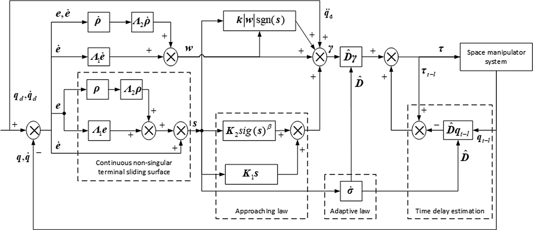
The operational control strategy of the proposed TDE-based adaptive sliding mode controller (42) is shown in Fig. 3.
The operational control strategy of the TDE-based adaptive sliding mode controller.

5. Simulation examples
Simulations are carried out for a free-floating three-bar space manipulator, as shown in Fig. 1. The system’s parameters are as follows:
 ${m_0} = 1430{\mathop{\rm kg}\nolimits} $
,
 ${m_1} = 35{\mathop{\rm kg}\nolimits} $
,
 ${m_2} = 22.5{\mathop{\rm kg}\nolimits} $
,
 ${m_3} = 21.9{\mathop{\rm kg}\nolimits} $
,
 ${J_0} = 7090{\mathop{\rm kg}\nolimits} {\cdot} {{\mathop{\rm m}\nolimits} ^2}$
,
 ${J_1} = 0.42{\mathop{\rm kg}\nolimits} {\cdot} {{\mathop{\rm m}\nolimits} ^2}$
,
 ${J_2} = 0.94{\mathop{\rm kg}\nolimits} {\cdot} {{\mathop{\rm m}\nolimits} ^2}$
,
 ${J_3} = 0.63{\mathop{\rm kg}\nolimits} {\cdot} {{\mathop{\rm m}\nolimits} ^2}$
,
 ${l_0} = 0.5{\mathop{\rm m}\nolimits} $
,
 ${l_{\rm{1}}} = {\rm{0}}{\rm{.35}}{\mathop{\rm m}\nolimits} $
,
 ${l_2} = 0.87{\mathop{\rm m}\nolimits} $
,
 ${l_3} = 0.63{\mathop{\rm m}\nolimits} $
,
 ${b_{\rm{1}}} = 0.25{\mathop{\rm m}\nolimits} $
,
 ${b_2} = 0.175{\mathop{\rm m}\nolimits} $
,
 ${b_3} = 0.315{\mathop{\rm m}\nolimits} $
,
 $v = 1.2{\rm{m/s}}$
,
 ${\theta _0} = - \dfrac{\pi}{6}rad$
,
 $d = {\rm{2}}{\rm{.3}}{\mathop{\rm m}\nolimits} $
,
 ${\theta _p} = 242^\circ $
,
 ${\dot x_P} = 0.95{\mathop{\rm m}\nolimits} /s$
,
 ${\dot y_P} = - 0.55{\mathop{\rm m}\nolimits} /s$
,
 ${\dot \theta _p} = 0.13{\rm{rad/s}}$
,
 $[{({{{\ddot{\textbf{q}}}}_l})_{int}}] = {[{0.05}\quad {}{0.05} \quad {}{0.05} ]^{\textrm{T}}}$
 $(^\circ {\rm{/}}{s^2})$
.
Assume
 $L = 0.01{\mathop{\rm s}\nolimits} $
,
 ${t_0} = 0s$
,
 ${t_f} = 66s$
,
 $[\Delta v] = 0.02{\rm{m/s}}$
,
 $\xi (0) = {[0.03\;\;0.02\;\;0.02]^{\textrm{T}}}$
. The controller parameters are
 ${{\textbf{D}}_I} = {\mathop{\rm diag}\nolimits} \left( {1,1,1,0.4,0.3,0.1} \right)$
,
 ${{\boldsymbol{\Lambda }}_{\rm{1}}} = {{\boldsymbol{\Lambda }}_{\rm{2}}} = {\mathop{\rm diag}\nolimits} \left( {30,30,30,30,30,30} \right)$
,
 ${{\textbf{K}}_{\rm{1}}} = {\mathop{\rm diag}\nolimits} \left( {2,2,2.4,2,2,2.4} \right)$
,
 ${{\textbf{K}}_{\rm{2}}} = {\mathop{\rm diag}\nolimits} ({\rm{0}}{\rm{.012}},0.0{\rm{12}},{\rm{2}}{\rm{.4}},{\rm{0}}{\rm{.012}},0.0{\rm{12}},{\rm{2}}{\rm{.4}})$
,
 ${{\alpha }_{1i}} = 0.8$
,
 ${{\alpha }_{2i}} = 1.4$
,
 ${{\alpha }_{3i}} = 2$
,
 ${\phi _i} = 0.002$
,
 ${k_{1i}} = 0.23$
,
 ${k_{2i}} = 0.2$
,
 ${{\zeta }_{1i}} = 0.5$
,
 ${{\upsilon }_i} = 0.1$
,
 ${\chi _i} = 0.1$
,
 $\beta = 0.{\rm{9}}$
,
 $i = 1, \cdots ,6$
.
Case 1
 $\psi = - \dfrac{\pi}{6}rad$
,
 $\phi = \dfrac{\pi}{3}$
, the initial position of the base centroid relative to center of the target is
 $x_{C0}^P = - 7.67m$
,
 $y_{C0}^P = 1.77m$
.
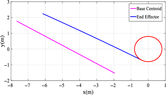
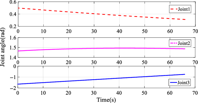
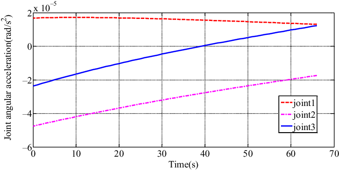
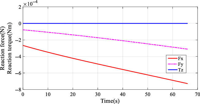
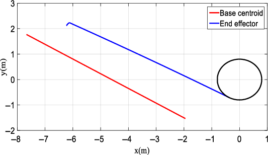
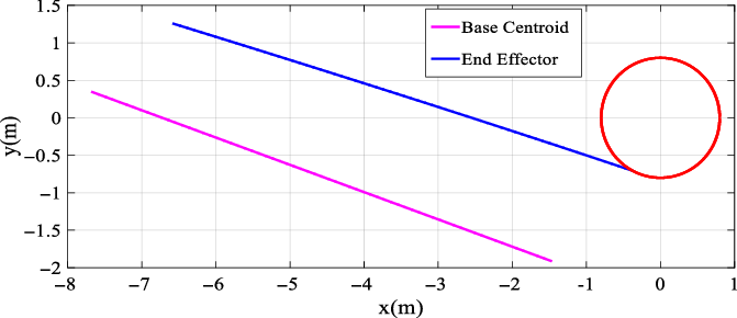
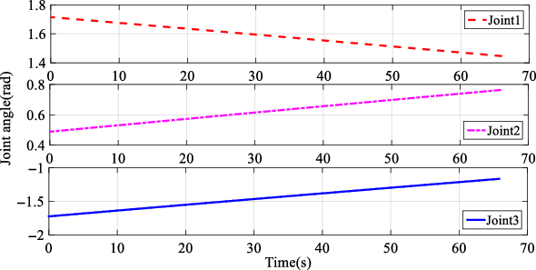
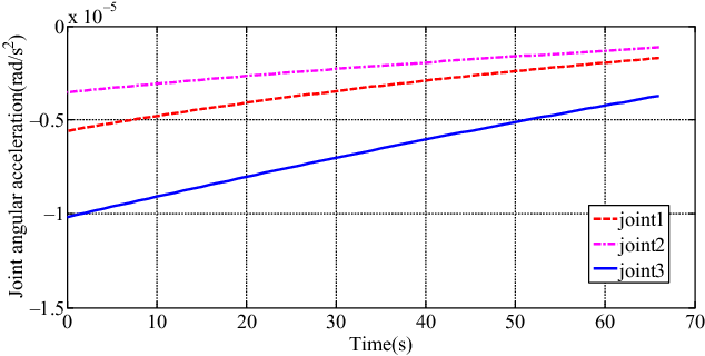
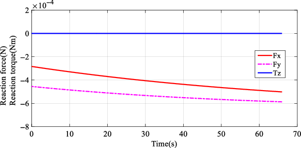
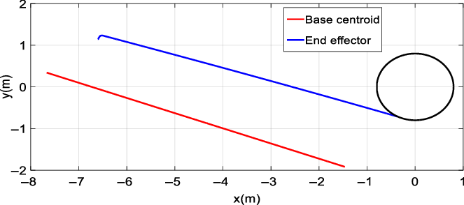
The simulation results of the RNS planning are shown in Figs. 4–7. Figure 4 shows the reactionless trajectories of the base centroid, the center of the end gripper. Figure 5 shows the reactionless joint trajectories, while Fig. 6 shows the reactionless joint angular accelerations. Figure 7 shows the reaction forces and reaction torque on the base.
The reactionless trajectories of the base centroid, the center of the end gripper (RNS planning,
 $\psi = - \dfrac{\pi}{6}rad$
).

The reactionless joint trajectories (RNS planning,
 $\psi = - \dfrac{\pi}{6}rad$
).

The reactionless joint angular accelerations (RNS planning,
 $\psi = - \dfrac{\pi}{6}rad$
).

The reaction forces (RNS planning,
 $\psi = - \dfrac{\pi}{6}rad$
).

The initial state is
 ${\theta _1} = 0.56rad$
,
 ${\theta _2} = 1.43rad$
,
 ${\theta _3} = - 1.92rad$
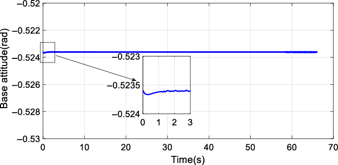
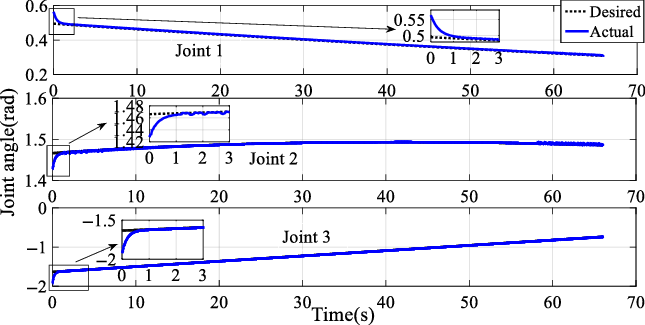
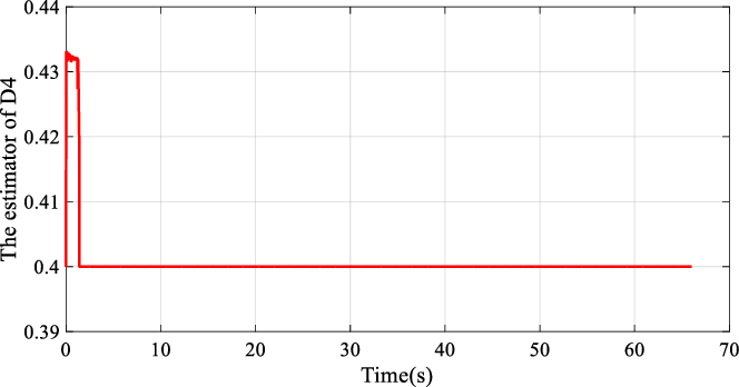
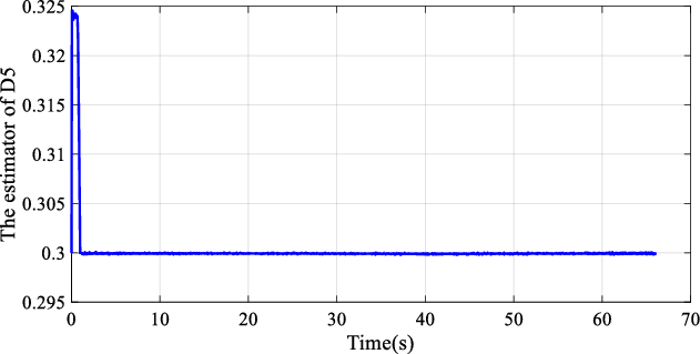
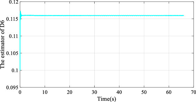
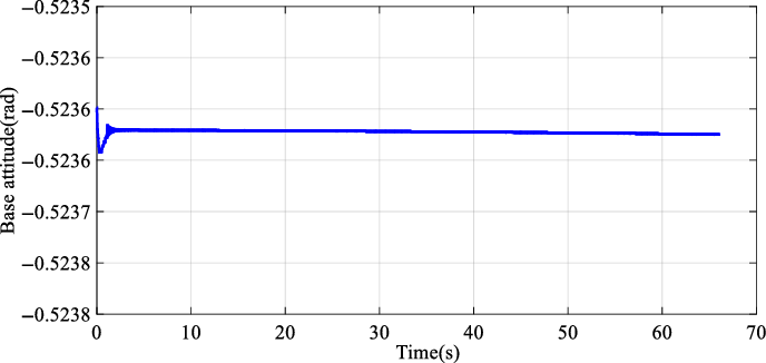
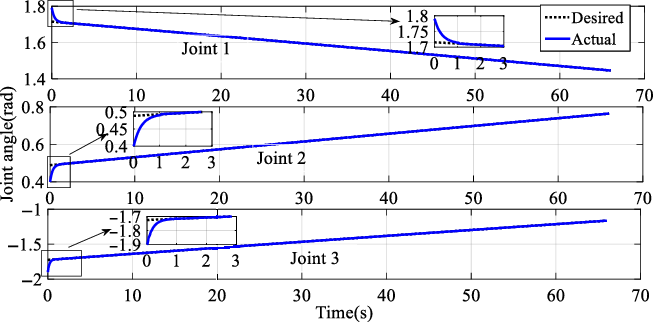
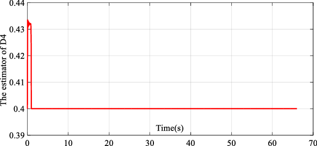
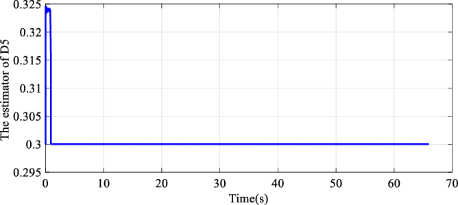
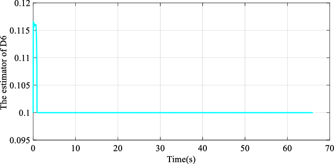
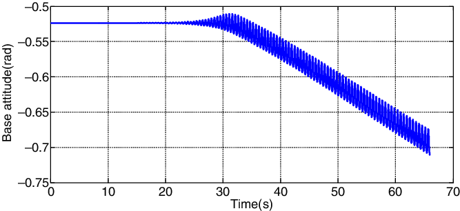
, and the simulation results from the proposed controller Eq. (47) (controller II) are shown in Figs. 8–13. Figure 8 shows the actual trajectories of the base centroid, the center of the end gripper. Figure 9 is the actual trajectory of the base’s attitude, while Fig. 10 depicts the tracking trajectories of joints. Figures 11, 12, and 13 are the estimators of
 ${{D}_4}$
,
 ${{D}_5}$
, and
 ${{D}_6}$
, respectively. When the end gripper comes into contact with the target handle,
 $\Delta v$
is
 ${\rm{0}}{\rm{.0064}}\,{\rm{m/s}}$
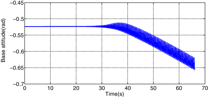
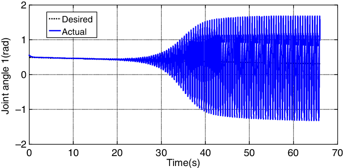
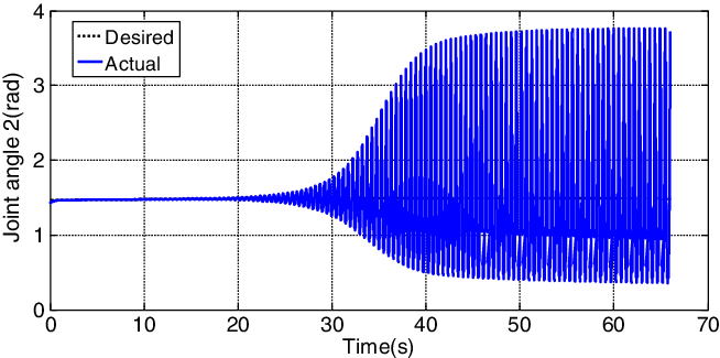
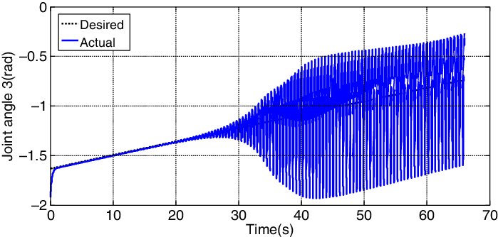
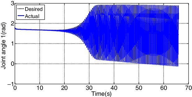
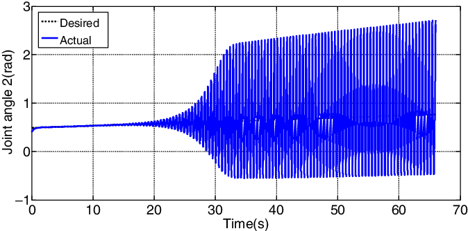
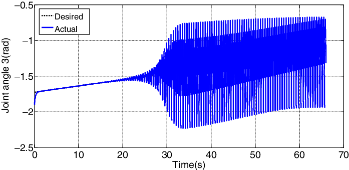
. The simulation results from the controller Eq. (33) (controller I) are shown in Figs. 14–17. Figure 14 is the actual trajectory of the base’s attitude, while Figs. 15–17 depict the tracking trajectories of joints 1–3, respectively.
The actual trajectories of the base centroid, the center of the end gripper (
 $\psi = - \dfrac{\pi}{6}rad$
, controller II).

The tracking trajectory of the base’s attitude (
 $\psi = - \dfrac{\pi}{6}rad$
, controller II).

The tracking trajectory of joints (
 $\psi = - \dfrac{\pi}{6}rad$
, controller II).

The estimator of
 ${{D}_4}$
(
 $\psi = - \dfrac{\pi}{6}rad$
, controller II).

The estimator of
 ${{D}_5}$
(
 $\psi = - \dfrac{\pi}{6}rad$
, controller II).

The estimator of
 ${{D}_6}$
(
 $\psi = - \dfrac{\pi}{6}rad$
, controller II).

The tracking trajectory of the base’s attitude (
 $\psi = - \dfrac{\pi}{6}rad$
, controller I).

The tracking trajectory of joint 1 (
 $\psi = - \dfrac{\pi}{6}rad$
, controller I).

The tracking trajectory of joint 2 (
 $\psi = - \dfrac{\pi}{6}rad$
, controller I).

The tracking trajectory of joint 3 (
 $\psi = - \dfrac{\pi}{6}rad$
, controller I).

Case 2
 $\psi = - \dfrac{\pi}{9}rad$
,
 $\phi = \dfrac{\pi}{3}$
, the initial position of the base centroid relative to center of the target is
 $x_{C0}^P = - 7.67m$
,
 $y_{C0}^P = 0.34m$
.
The simulation results of the RNS planning are shown in Figs. 18–21. Figure 18 shows the reactionless trajectories of the base centroid, the center of the end gripper. Figure 19 shows the reactionless joint trajectories, while Fig. 20 shows the reactionless joint angular accelerations. Figure 21 shows the reaction forces and the reaction torque on the base.
The reactionless trajectories of the base centroid, the center of the end gripper (RNS planning,
 $\psi = - \dfrac{\pi}{9}rad$
).

The reactionless joint trajectories (RNS planning,
 $\psi = - \dfrac{\pi}{9}rad$
).

The reactionless joint angular accelerations (RNS planning,
 $\psi = - \dfrac{\pi}{9}rad$
).

The reaction forces (RNS planning,
 $\psi = - \dfrac{\pi}{9}rad$
).

The initial state is
 ${\theta _1} = 1.79rad$
,
 ${\theta _2} = 0.40rad$
,
 ${\theta _3} = - 1.90rad$
, and the simulation results from the proposed controller Eq. (47) (controller II) are shown in Figs. 22–27. Figure 22 shows the actual trajectories of the base centroid, the center of the end gripper. Figure 23 is the actual trajectory of the base’s attitude, while Fig. 24 depicts the tracking trajectories of joints. Figures 25, 26, and 27 are the estimators of
 ${{D}_4}$
,
 ${{D}_5}$
, and
 ${{D}_6}$
, respectively. When the end gripper comes into contact with the target handle,
 $\Delta v$
is
 ${\rm{0}}{\rm{.0192}}\,{\rm{m/s}}$
. The simulation results from the controller Eq. (33) (controller I) are shown in Figs. 28–31. Figure 28 is the actual trajectory of the base’s attitude, while Figs. 29–31 depict the tracking trajectories of joints 1–3, respectively.
The actual trajectories of the base centroid, the center of the end gripper (
 $\psi = - \dfrac{\pi}{9}rad$
, controller II).

The tracking trajectory of the base’s attitude (
 $\psi = - \dfrac{\pi}{9}rad$
, controller II).

The tracking trajectories of joints (
 $\psi = - \dfrac{\pi}{9}rad$
, controller II).

The estimator of
 ${{D}_4}$
(
 $\psi = - \dfrac{\pi}{9}rad$
, controller II).

The estimator of
 ${{D}_5}$
(
 $\psi = - \dfrac{\pi}{9}rad$
, controller II).

The estimator of
 ${{D}_6}$
(
 $\psi = - \dfrac{\pi}{9}rad$
, controller II).

The tracking trajectory of the base’s attitude (
 $\psi = - \dfrac{\pi}{9}rad$
, controller I).

The tracking trajectory of joint 1 (
 $\psi = - \dfrac{\pi}{9}rad$
, controller I).

Figures 6 and 20 show that the reactionless joint angular accelerations are less than their allowable values, and Figs. 7 and 21 show that the reaction forces and reaction torque on the base are almost 0. It can be seen from Figs. 9 and 23 that the base’s attitude changes slightly at the beginning, and then remains to be
 $ - \dfrac{\pi}{6}rad$
by the controller II. Meanwhile, it can be seen from Figs. 10 and 24 that the joint angles gradually track the desired reactionless trajectories and that the errors converge to zero after about 2 s by the controller II. From Figs. 14–17 and 28–31, it can be seen serious chattering happens after 20 s, and the reactionless desired joint trajectories cannot be tracked efficiently by the controller I .
The tracking trajectory of joint 2 (
 $\psi = - \dfrac{\pi}{9}rad$
, controller I).

The tracking trajectory of joint 3 (
 $\psi = - \dfrac{\pi}{9}rad$
, controller I).

6. Conclusions
The Lagrange dynamic model of a free-floating three-bar space manipulator was established. The RNS motion planning algorithm of the manipulator’s pregrasping a rotating target was derived, and the vector norm constraint algorithm of RNS planning was addressed. Then an augmented adaptive sliding mode controller based on TDE was proposed, in which the adaptive estimated inertia matrix was introduced to decrease the estimation errors and avoid serious chattering and accurate dynamics were not required. The proposed RNS planning algorithm and the proposed controller ensured that joint angular accelerations were less than their allowable values and each joint tracked the desired reactionless trajectory with the base’s attitude reactionless.
Acknowledgments
This work was supported by the National Natural Science Foundation of China (grant number 51741502), the Natural Science Foundation of Fujian Province (grant number 2020J01450), and Fujian Provincial Industrial Robot Basic Components’Technology Research Platform (grant number 2014H21010011).
Author Contributions
Xiaoyan Yu conceived and designed the study. Xiaoyan Yu and Jianyu Zhang performed simulations. Xiaoyan Yu and Jianqiao Guo derived the dynamic equations and wrote the article.
Conflicts of Interests
The authors declare none.