


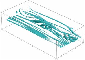


1. Introduction
Experimental studies (see e.g. Bippes Reference Bippes1999; Borodulin et al. Reference Borodulin, Ivanov, Kachanov and Roschektayev2013, Reference Borodulin, Ivanov, Kachanov and Roschektayev2016b; Borodulin, Ivanov & Kachanov Reference Borodulin, Ivanov and Kachanov2017) have shown that the problem of mechanisms of transformation of freestream turbulence into the cross-flow (CF) instability modes is very important for understanding the physics of the transition process and for designing modern advanced methods of transition prediction, such as the amplitude methods (Mack Reference Mack1975, Reference Mack1977), the variable  $N$-factor methods (Crouch Reference Crouch1997; Crouch & Ng Reference Crouch and Ng1997; Crouch et al. Reference Crouch, Ng, Kachanov, Borodulin and Ivanov2015) and their modifications (Kachanov, Borodulin & Ivanov Reference Kachanov, Borodulin and Ivanov2016; Borodulin et al. Reference Borodulin, Ivanov and Kachanov2017), as well as newly developing amplitude methods of transition prediction (Ustinov Reference Ustinov2013, Reference Ustinov2017).
The number of studies of the boundary-layer receptivity to freestream vorticity was rather limited for a long time, but has increased rapidly during the past decade. The majority of these studies are devoted either to purely two-dimensional receptivity problems or to three-dimensional receptivity of two-dimensional boundary layers. Some rather detailed reviews of early investigations of various receptivity problems can be found in the books by Kachanov, Kozlov & Levchenko (Reference Kachanov, Kozlov and Levchenko1982), Zhigulev & Tumin (Reference Zhigulev and Tumin1987) and Boiko et al. (Reference Boiko, Dovgal, Grek and Kozlov2002) and in the reviews by Leehey (Reference Leehey1980), Nishioka & Morkovin (Reference Nishioka and Morkovin1986), Kachanov (Reference Kachanov2000) and Saric, Reed & Kerschen (Reference Saric, Reed and Kerschen2002).
The case of the distributed boundary-layer receptivity to steady streamwise vortices was first investigated in a theoretical work by Goldstein & Leib (Reference Goldstein and Leib1993) (see also Wundrow & Goldstein (Reference Wundrow and Goldstein2001) and references therein), while the first quantitative experimental data were obtained by Kendall (Reference Kendall1985, Reference Kendall1990, Reference Kendall1991). Later the experimental results by Kendall (Reference Kendall1990) were compared with calculations by Bertolotti (Reference Bertolotti, Duck and Hall1996, Reference Bertolotti1997) in a joint work by Bertolotti & Kendall (Reference Bertolotti and Kendall1997). Very good agreement has been found for the mechanism of excitation of streamwise streaks under the influence of freestream streamwise vortices. A very similar problem has been studied in detail in experiments by Boiko (Reference Boiko2002a,Reference Boikob) for cases of two-dimensional (Blasius) and three-dimensional (swept-wing) boundary layers, respectively. However, receptivity coefficients have not been obtained in those experiments.
A receptivity mechanism of localised transformation of wall-normal steady freestream vortices into steady boundary-layer perturbations (again streaks) occurring in the vicinity of a blunt-leading-edge plate was investigated theoretically by Goldstein, Leib & Cowley (Reference Goldstein, Leib and Cowley1992), Goldstein & Sescu (Reference Goldstein and Sescu2008) and theoretically and experimentally by Kogan et al. (Reference Kogan, Shumilkin, Ustinov and Zhigulev2001) and Ustinov (Reference Ustinov2001a). In particular, it was shown that interaction of such vortices with the leading-edge non-uniformity leads to the formation of very strong streaks (streamwise vortices) inside the boundary layer. The theory presented in the latter works predicted very well the experimental observations. A similar study performed for a swept flat-plate leading edge has shown somewhat weaker excitation of streaky structures in comparison with the case of a two-dimensional leading edge (Ustinov Reference Ustinov2001b). Wu & Choudhari (Reference Wu and Choudhari2003) were also among the first who investigated the effect of unsteady freestream-vortex-induced streaks in boundary layers.
The first quantitative experimental study of the boundary-layer receptivity to unsteady freestream vortices was performed by Kachanov, Kozlov & Levchenko (Reference Kachanov, Kozlov and Levchenko1979a) and Kachanov et al. (Reference Kachanov, Kozlov, Levchenko and Maksimov1979b) in as early as 1978 (see also Kachanov et al. Reference Kachanov, Kozlov and Levchenko1982) for the case of a two-dimensional problem with the spanwise orientation of the disturbance vorticity vector. It was found, in particular, that far from the leading edge such vortical disturbances are not able to excite measurable Tollmien–Schlichting (TS) waves in the boundary layer if the model surface is smooth. This result agreed with the theoretical study by Rogler & Reshotko (Reference Rogler and Reshotko1975). However, a very strong mechanism of TS-wave excitation by freestream vortices was found by Kachanov et al. (Reference Kachanov, Kozlov and Levchenko1979a,Reference Kachanov, Kozlov, Levchenko and Maksimovb) in the vicinity of the flat-plate leading edge. Later, similar problems were studied experimentally, numerically and theoretically by Saric, Reed & Kerschen (Reference Saric, Reed and Kerschen1994) and Saric et al. (Reference Saric, Wei, Rasmussen and Krutckoff1995). Some more extended results, including the influence of external disturbances on transition, were obtained in experiments by Saric, Reed & White (Reference Saric, Reed and White1999). The problem of transformation of unsteady freestream vortices into streaky structures on a blunt two-dimensional leading edge was examined theoretically by Ustinov (Reference Ustinov2002) for a leading-edge-normal orientation of the freestream vorticity. A reduction of efficiency of streak excitation with frequency was found. This problem was also investigated recently by Goldstein & Sescu (Reference Goldstein and Sescu2008) in the high-Reynolds-number limit. It is shown that the resulting streamwise velocity profiles in the boundary layer become inflexional only if the upstream vortices are unsteady. The problem of excitation of three-dimensional TS waves by freestream turbulence was solved in a nonlinear formulation by Ustinov (Reference Ustinov2014). The linear dependence of the critical N-factor on the logarithm of the freestream turbulence level observed in experiments was substantiated theoretically.
Most investigations of the problem of unsteady vortex receptivity of boundary layers performed after the early experiments indicated above were theoretical until the beginning of the 2000s. The problem of resonant scattering of a periodical vortex street on a wall with a weak waviness was investigated theoretically by Zavol'skii, Reutov & Rybushkina (Reference Zavol'skii, Reutov and Rybushkina1983) within the framework of a locally parallel theory based on solving the Orr–Sommerfeld equation. This approach was developed in subsequent theoretical studies (Choudhari & Streett Reference Choudhari and Streett1992; Crouch Reference Crouch1994) for problems of localised (scattering on concentrated non-uniformities and suction regions) and distributed (scattering on natural base-flow non-uniformities) vortex receptivity. Another approach, based on asymptotic theory (at high Reynolds numbers) was developed in studies by Goldstein (Reference Goldstein1983, Reference Goldstein1985), Ruban (Reference Ruban1985) and Wu (Reference Wu2001b) for acoustic receptivity, and by Kerschen (Reference Kerschen1990, Reference Kerschen1991), Goldstein & Leib (Reference Goldstein and Leib1993), Choudhari (Reference Choudhari1994, Reference Choudhari1996), Wu (Reference Wu2001a,Reference Wub) and others for investigation of localised and distributed boundary-layer receptivity to unsteady vortical perturbations (see also Kachanov Reference Kachanov2000; Saric et al. Reference Saric, Reed and Kerschen2002, for reviews).
The majority of studies performed in the 1980s and 1990s were devoted to two-dimensional disturbances. Many subsequent theoretical studies of the problem of vortex receptivity published during the past decade were discussed in recent papers by Ricco & Wu (Reference Ricco and Wu2007), Ricco, Luo & Wu (Reference Ricco, Luo and Wu2011), Wu, Zhao & Luo (Reference Wu, Zhao and Luo2011) (the asymptotic approach) and Gianetti & Luchini (Reference Gianetti and Luchini2006), Bottaro (Reference Bottaro2010) (studies based on use of adjoint equations). Recently, it was shown in experiments by Borodulin, Ivanov & Kachanov (Reference Borodulin, Ivanov and Kachanov2010a,Reference Borodulin, Ivanov and Kachanovb), Borodulin et al. (Reference Borodulin, Ivanov, Kachanov and Roschektayev2013, Reference Borodulin, Ivanov, Kachanov and Roschektayev2016b) and in direct numerical simulations (DNS) by Schrader, Amin & Brandt (Reference Schrader, Amin and Brandt2010); Tempelmann, Hanifi & Henningson (Reference Tempelmann, Hanifi and Henningson2012) that the swept-wing boundary layer is very receptive to streamwise elongated unsteady freestream vortices. A very strong influence of steady modulation of incident flow velocity associated with streaks was also found in the calculations by Kurz & Kloker (Reference Kurz and Kloker2015).
Similar to experiments by Kachanov et al. (Reference Kachanov, Kozlov and Levchenko1979a), a quantitative experimental study of the two-dimensional problem of localised vortex receptivity in the presence of controlled surface roughness was carried out by Dietz (Reference Dietz1999). In this case (in contrast to experiments by Kachanov et al. (Reference Kachanov, Kozlov and Levchenko1979a) performed on a smooth surface) the excitation of the TS waves was detected successfully; the properties of the excited disturbances were investigated in detail, especially downstream of the surface-roughness region. This mechanism was studied theoretically by Wu (Reference Wu2001b) (for the experimental conditions of work by Dietz Reference Dietz1999) within the framework of the asymptotic two-dimensional theory. Good agreement with measurements was found. The first experimental study of a localised receptivity mechanism for scattering of (quasi-two-dimensional) freestream vortices on spanwise localised (i.e. ‘three-dimensional’) surface vibrations was performed by Borodulin et al. (Reference Borodulin, Kachanov, Roschektayev and Bake2004b) for the Blasius boundary layer. The corresponding receptivity coefficients for excitation of three-dimensional TS waves were obtained as functions of the spanwise wavenumber.
In the experiments by Borodulin et al. (Reference Borodulin, Ivanov, Kachanov and Roschektayev2013) a problem of localised excitation of unsteady CF instability modes owing to scattering of freestream vortices on surface roughness was investigated quantitatively in detail. It turned out that this kind of receptivity mechanism, called there the ‘roughness-vortex’ receptivity, is rather weak and it was necessary to apply a special type of wall roughness, called the ‘phased roughness’ in order to concentrate the energy of the excited CF instability modes in two spanwise-wavenumber harmonics only and to increase, in this way, the accuracy of measurements considerably. It was found, in particular, that the localised roughness-vortex receptivity characteristics are independent practically of the vortex offset parameter (characterising a distance between the surface and the freestream-vortex street) when the receptivity coefficients are defined for the streamwise component of the freestream velocity fluctuations measured at the boundary-layer edge. It was also shown by Borodulin et al. (Reference Borodulin, Ivanov, Kachanov and Roschektayev2013) that the efficiency of excitation of the CF modes by this mechanism increases with frequency of the excited CF wave in a linear way. This growth of efficiency can be explained through the reduction of the angle of inclination of the CF wave front (or the CF vortex axis) with respect to the axis of the unsteady freestream vortices. In general, the results obtained by Borodulin et al. (Reference Borodulin, Ivanov, Kachanov and Roschektayev2013) have provided, for the first time, some quantitative experimental information, which can be used for estimation of initial amplitudes and phases of the CF modes excited in swept-wing boundary layers in presence of freestream vortices and surface roughness. Being linear (in a sense of independence of the receptivity coefficients from amplitudes the two kinds of disturbances) and being defined in Fourier space, the estimated receptivity coefficients are independent of the particular shape and amplitude of the surface roughness and provide an experimental basis for quantitative verification of vortex receptivity theories for three-dimensional boundary layers.
Almost simultaneously a problem of localised excitation of unsteady CF instability modes due to scattering of freestream vortices on surface vibrations was investigated experimentally in detail by Borodulin et al. (Reference Borodulin, Ivanov, Kachanov and Roschektayev2016b). It turned out that this kind of receptivity mechanism, called there the ‘vibration-vortex’ receptivity, is significantly stronger than the roughness-vortex receptivity studied by Borodulin et al. (Reference Borodulin, Ivanov, Kachanov and Roschektayev2013). Similar to the roughness-vortex receptivity case discussed previously, it was found that the localised vibration-vortex receptivity characteristics are also independent of the vortex offset parameter in case if the receptivity coefficients are defined for the streamwise component of the freestream velocity fluctuations measured at the boundary-layer edge. It was also found by Borodulin et al. (Reference Borodulin, Ivanov, Kachanov and Roschektayev2016b) that the efficiency of excitation of the CF modes by this mechanism increases with the surface vibration frequency  $f_{sur}$, with frequency of the excited CF wave
 $f_{CF}$, and with the parameter of the surface vibration non-stationarity
 $k = f_{sur}/f_{vor}$ (here
 $f_{vor}$ is the freestream vortex frequency). The conclusion on the strong enhancement of the boundary-layer roughness-vortex receptivity to freestream vortices when the angle between axes of the freestream vortices and axes of the excited CF vortices (waves) decreases has been corroborated for the case of the vibration-vortex receptivity mechanism. Both the roughness-vortex localised receptivity coefficients obtained by Borodulin et al. (Reference Borodulin, Ivanov, Kachanov and Roschektayev2013) and the vibration-vortex localised receptivity coefficients estimated by Borodulin et al. (Reference Borodulin, Ivanov, Kachanov and Roschektayev2016b) are independent of the particular shape and amplitude of the surface vibrations.
The first quantitative experimental investigation of the distributed problem of boundary-layer receptivity to unsteady freestream vortices was reported by Würz et al. (Reference Würz, Herr, Wagner and Kachanov2002) for the case of scattering of three-dimensional vortices (which were normal to the incident flow and leading edge) on ‘natural’ base-flow and surface non-uniformities for the case of a two-dimensional aerofoil section. Excitation of three-dimensional TS waves was detected and studied. Later, some more detailed results on the distributed vortex receptivity were obtained for the flat-plate boundary layer in the presence and absence of two-dimensional controlled surface roughness for cases of both wall-normal (Borodulin et al. Reference Borodulin, Ivanov, Kachanov and Fedenkova2007) and surface-parallel (Borodulin et al. Reference Borodulin, Fedenkova, Ivanov, Kachanov and Komarova2005, Reference Borodulin, Ivanov, Kachanov and Komarova2006) orientations of the freestream vorticity vectors. Similar results were obtained for the case of the wall-normal freestream vortices in experiments by Borodulin et al. (Reference Borodulin, Ivanov, Kachanov, Mischenko and Fedenkova2016a) in the case of a two-dimensional boundary layer with adverse streamwise pressure gradient.
Almost the same experimental approaches were used by Ivanov, Kachanov & Mischenko (Reference Ivanov, Kachanov and Mischenko2012) and Borodulin et al. (Reference Borodulin, Ivanov, Kachanov and Mischenko2018) in experimental investigations of mechanisms of localised and distributed excitation of Görtler instability modes by freestream vortices (Borodulin et al. Reference Borodulin, Ivanov, Kachanov and Mischenko2018) and by surface non-uniformities (Ivanov et al. Reference Ivanov, Kachanov and Mischenko2012). It was shown, in particular, that localised receptivity mechanisms associated with scattering of freestream vortices on surface roughness or vibrations are very inefficient, whereas the distributed receptivity mechanism of excitation of Görtler modes by streamwise freestream vortices is very strong. The corresponding distributed receptivity coefficients were estimated. The problem of excitation of non-stationary Görtler vortices by freestream turbulence was also investigated recently theoretically and numerically by Marensi & Ricco (Reference Marensi and Ricco2017) and Viaro & Ricco (Reference Viaro and Ricco2018). The excited disturbances were identified as either Görtler vortices or Klebanoff modes.
Thus, the analysis of the literature has shown that quantitative investigations of the distributed swept-wing boundary-layer receptivity to unsteady freestream vortices (at excitation of unsteady CF instability modes) have not been performed experimentally at present except for those carried out by the authors of the present paper and published, as a preliminary, in Borodulin et al. (Reference Borodulin, Ivanov and Kachanov2010a,Reference Borodulin, Ivanov and Kachanovb). Moreover, as far as the localised boundary-layer receptivity increases significantly when the angles between the freestream vortex axes and the wave-fronts of the excited CF waves become smaller, the most efficient distributed mechanism of the swept-wing boundary-layer vortex receptivity is also expected for streamwise elongated freestream vortices. The main goal of the present experiments is to clarify this point and to investigate quantitatively the problem of excitation of unsteady CF instability modes due to scattering of unsteady streamwise elongated freestream vortices on natural base-flow non-uniformities. In particular, this goal incudes estimation of the corresponding ‘distributed vortex receptivity coefficients’. The results of this investigation are described in the present two-part paper.
Prior to starting the main measurements, a theoretical analysis of the corresponding distributed-receptivity problem was performed based on experience obtained in our previous experiments carried out for distributed excitation of TS waves by freestream vortices in two-dimensional boundary layers. The main goal of this analysis was to find a proper definition of the distributed receptivity coefficients (functions) and to develop a procedure of determination of these functions based purely on the experimental data.
It is important to note here that the distributed (in the streamwise direction) receptivity mechanisms differ very significantly from the corresponding localised ones. The localised receptivity mechanisms provide excitation of boundary-layer instability waves at a certain streamwise location. Then, the excited waves evolve farther downstream according to the laws of the corresponding instability mechanism. Meanwhile, the distributed receptivity mechanism provides permanent excitation of instability waves in a broad range of the streamwise coordinate. As a result, the previously excited instability waves are superimposed with newly excited ones and the receptivity spatial domain is overlapped with the linear-stability spatial domain leading to a very significant complication of the problem under study. In this case, the most difficult issue is to find a way of separating the receptivity problem from the instability one.
The theoretical analysis has shown that in every regime of measurements it is necessary to perform two experiments simultaneously.
(i) A distributed receptivity (DR) experiment itself with the distributed excitation of the CF waves by freestream vortices.
(ii) A complementary stability (S) experiment on the development of pure CF waves in the absence of their distributed excitation.
All experiments were carried out at fully controlled disturbance conditions. In the DR experiments (the distributed receptivity measurements themselves), the freestream vortices were generated by means of a special technique based on vibrating wire with a spanwise non-uniformity (a swelling) on it. In the S experiments (the stability measurements), the CF wave trains were excited by a point source mounted on the same experimental model.
The analysis has also shown that the distributed receptivity mechanism can be efficient only in case when the excited CF modes are amplified downstream, rather than attenuate or have a neutral behaviour. Therefore, it was decided to perform all main measurements at a freestream speed, which is higher than that used in previous stability and receptivity experiments carried out on a similar experimental model (see, e.g., Borodulin et al. Reference Borodulin, Gaponenko, Ivanov, Kachanov and Crouch2000; Gaponenko et al. Reference Gaponenko, Ivanov, Kachanov and Crouch2002). Thus, the freestream velocity used in the present experiments was approximately twice as high. The measurements showed that the most amplified CF modes had frequencies between zero and 50 or 60 Hz.
The main goal of the present study was to obtain (for the first time) quantitative experimental information about the distributed vortex-receptivity coefficients for a swept-wing boundary layer at excitation of unsteady CF instability modes.
To attain this goal, our experiments consisted of the following most important stages. First of all (i) we have carried out detailed measurements of the base-flow under study. Then, the S experiments included: (ii) excitation of wave trains of ‘pure’ CF instability modes by a point source mounted on the experimental model surface and performing detailed measurements of amplitudes and phases of the excited CF instability waves, (iii) performing Fourier decomposition of the excited CF wave trains into oblique (in general) modes of the frequency-spanwise-wavenumber spectrum, (iv) obtaining all main stability characteristics of the boundary layer under study with respect to the excited unsteady CF modes. The third stage of the experiments called the DR experiment included: (v) excitation in the incident flow of fully controlled time-periodic, streamwise-elongated (and spanwise-localised) vortices and examination of their characteristics, (vi) performing measurements of amplitudes and phases of CF instability waves excited in the boundary layer owing to streamwise distributed scattering of the controlled freestream vortices on the natural spatial non-uniformity of the growing boundary layer, (vii) performing Fourier decomposition of both freestream vortices and excited CF waves into oblique (in general) modes of the frequency-spanwise-wavenumber spectrum, (viii) approximation of streamwise distributions of spectral amplitudes and phases of the excited CF modes by analytical solutions of an evolutionary equation describing their distributed excitation and (ix) estimation of the corresponding distributed vortex-receptivity coefficients.
This paper (Part 1 of the present study) is devoted to description of: (a) the developed new experimental approach, (b) the base-flow structure, (c) the structure of fully controlled freestream vortices, (d) a description of primary results of main receptivity and instability measurements obtained in DR and S experiments and (e) experimental demonstration of great efficiency of the distributed vortex receptivity mechanism under study. The corresponding theoretical background, as well as the results of estimation of quantitative characteristics of the boundary-layer instability (S experiments) and its distributed vortex receptivity (DR experiments) are presented in Part 2 of this study (see Borodulin et al. Reference Borodulin, Ivanov, Kachanov and Roschektayev2021).
The experiments described in the present paper (Part 1), as well as in Part 2 (Borodulin et al. Reference Borodulin, Ivanov, Kachanov and Roschektayev2021), were performed in as early as 2002 within the framework of a research contract between the Khristianovich Institute of Theoretical and Applied Mechanics (ITAM) and the Boeing Operations International, Inc. However, the results of these experiments were published previously only in technical reports (Kachanov et al. Reference Kachanov, Borodulin, Ivanov and Roschektayev2002a,Reference Kachanov, Borodulin, Ivanov and Roschektayevb), which are unavailable for the scientific community. A very brief description of these experiments has appeared also in the proceedings of a conference ICMAR-2010 (Borodulin et al. Reference Borodulin, Ivanov and Kachanov2010a,Reference Borodulin, Ivanov and Kachanovb) published on a CD, access to which is essentially restricted to Russian participants of this conference held in Novosibirsk.
2. Experimental set-up and base flow characteristics
2.1. Experimental model and instrumentation
The experiments were conducted in a low-turbulence subsonic wind tunnel T-324 of ITAM. The same experimental model was used in the two sets of measurements (DR and S) described in the introduction. The model was mounted in the wind-tunnel test section ( $1 \ \textrm {m}\times 1 \ \textrm {m}\times 4\ \textrm {m}$) at zero angle of attack. The three-dimensional boundary layer of a swept wing was simulated on a swept flat plate having elliptic leading edge. The chordwise pressure gradient was induced by a contoured wall bump (uniform in the spanwise direction) mounted on the test-section ceiling just above the plate. Both the plate and the bump had the same sweep angle
 $\chi = 25^{\circ }$. A view from above and a side view on the model are given in figure 1. This experimental model is the same as that used by Borodulin et al. (Reference Borodulin, Ivanov, Kachanov and Roschektayev2013, Reference Borodulin, Ivanov, Kachanov and Roschektayev2016b). In contrast to some earlier experiments performed also on a similar experimental model (see, e.g., Gaponenko, Ivanov & Kachanov Reference Gaponenko, Ivanov and Kachanov1995a,Reference Gaponenko, Ivanov and Kachanovb; Gaponenko et al. Reference Gaponenko, Ivanov, Kachanov and Crouch2002; Crouch et al. Reference Crouch, Gaponenko, Ivanov and Kachanov1997; Ivanov, Kachanov & Koptsev Reference Ivanov, Kachanov and Koptsev1998, Reference Ivanov, Kachanov and Koptsev2001), the present model was modified. Namely, it was equipped with two contoured sidewalls in order to diminish the influence of the wind-tunnel test-section walls and to provide better satisfaction of the sweep condition. Note that the turbulence level
 $\varepsilon$ in this wind tunnel at a freestream velocity of approximately
 $5\text {--}15\ \textrm {m}\ \textrm {s}^{-1}$ is usually less than 0.02 % (in the frequency range higher than 1 Hz). However, the contoured wall bump and the sidewalls of the present experimental model described previously introduced some additional (low-frequency) disturbances into the flow, and the root-mean-square value of
 $\varepsilon$ (defined as
 $\varepsilon = u^\prime /U_e$) was higher at the conditions of the present experiments, around 0.06 % (in the same frequency range).
Sketch of experimental model. Dimensions are in millimetres.

The main coordinate systems used in the present experiments are the following. The  $(x, z)$ system is connected to the incoming freestream direction (upstream of the model) with the mean velocity vector
 $\boldsymbol {C}_{{o}}$ parallel to the
 $x$-axis. The
 $x'$-axis is directed along the chord and starts at the leading edge of the model. The
 $z'$-axis is parallel to the leading edge. The
 $(x^{\ast },z^{\ast })$ coordinate system is local, such that the
 $x^{\ast }$-axis is directed along the local mean velocity vector
 $\boldsymbol {C}_{{e}}$ of the potential flow near the external edge of the boundary layer. It is also convenient to use an additional axis
 $x_c$, which is parallel to the
 $x$-axis but has always its origin on the swept-plate leading edge, as well as an additional axis
 $z'_c$, which is similar to the
 $z'$-axis but always has its origin at the model centreline, i.e. at
 $z = 0$.
All main measurements were carried out by means of an AN-1003 hot-wire anemometer unit from AA Lab Systems. Two kinds of measurements were performed: (i) single-wire measurements in which most results were obtained and (ii) double-wire measurements for investigation of the base-flow structure and the freestream vortex shape. The main measurements were carried out both inside and outside the boundary layer. Inside the boundary layer a single-wire probe of the hot-wire anemometer was used in the present experiments. Meanwhile, the measurements outside the boundary layer (including its external edge) were performed with both single- and double-wire probes (X- and V-shaped) in order to quantify properly the vortex input, i.e. to obtain detailed information about the freestream vortex shape and about all three components of the associated freestream velocity fluctuations in the vicinity of the boundary-layer edge.
A sketch of instrumentation is shown in figure 2 and is common for cases (i) and (ii), as well as for the DR and S experiments. This instrumentation was used for the signal generation, for the data acquisition and for the initial signal processing. In the case of the double-wire measurements, the output signals of ‘channel 1’ and ‘channel 2’ of a hot-wire anemometer were linearised by two analogue linearisers (DISA 55D10) and then processed one after the other using the same branch of the data processing system. In the case of the single-wire measurements, only one of the channels was used. In both cases, the mean value of the lineariser output voltage (i.e. the DC component of the voltage), proportional to the  $x$ component of the mean flow velocity, was measured by a voltmeter and introduced into a personal computer through channel Ain0 of an A/D converter (MacADIOS-adio). The AC component of the voltage from the lineariser output (proportional to the
 $x$ component of the flow velocity fluctuations) was filtered by a filter (DISA 55D25) within the range from 1 Hz to 2 kHz in order to cut off the DC component and the high-frequency electronic noise of the hot-wire anemometer and lineariser. Then, the signal was introduced into the computer through channel Ain1 of the A/D converter. The shape of the velocity oscillations was observed by means of an oscilloscope (as well as on a computer monitor) synchronised with the reference signal that fed the disturbance source. The third channel of the A/D converter (called Aout) was used for triggering the process of the signal ensemble averaging.
Sketch of the instrumentation used.

Input signals for the freestream vortex generator (in the DR experiment) and for the point disturbance surface (in the S experiment), as well as the reference signal, were produced by an eight-channel, computer-controlled electronic unit (VS-II) designed and manufactured by our group in the 1990s. The VS-II unit accepted data from the computer and stored them in its RAM. In ‘playback’ mode, the clock pulses from an external signal generator went to the counter, which advanced the RAM address bus. The data bus was connected to eight D/A converters with amplifiers.
For three studied disturbance frequencies  $f = 24.59$, 34.88 and 44.78 Hz, the clock frequency was set at
 $f_c = 25\,180$, 35 721 or 45 851 Hz, respectively (i.e.
 $f_c = 1024f$ in all regimes). The length of every signal realisation produced by the VS-II unit was equal to
 $T_{sam} = 2/f$, that is, it corresponded to two periods of the disturbance excited in the flow. The clock frequency was measured by a frequency meter and kept constant with an accuracy of
 ${\pm }0.5\ \textrm {Hz}$. The signals generated by channels 7 and 8 of the VS-II unit were used in the DR experiments for feeding the stepping motors, which produced oscillations of the wire exciting the freestream vortices (see § 2.2 for further details). The signal produced by channel 1 was used for feeding the loudspeaker connected with the point source used in the S experiments (see § 2.3 for further details). The output signal from channel 1 of the VS-II unit was amplified by a power amplifier to feed the loudspeaker, whereas the output signals from channels 7 and 8 were connected directly to two stepping motors.
In both DR and S experiments the reference signal used for ensemble averaging of the hot-wire signals was produced by channel 1 of the VS-II unit, that is, this signal had the same frequency  $f$ as the disturbances excited in the flow. The quantity of realisations during ensemble averaging was equal to 10 or 15. The length of the realisation was equal to 10 periods of the excited disturbance in all regimes providing the averaging of 100–150 periods during the frequency Fourier analysis of the data.
2.2. Generator of three-dimensional freestream vortices in DR experiments
2.2.1. Mechanical part of vortex generator
The method of the freestream vortex generation was similar to that used in several other experiments (see e.g. Borodulin et al. Reference Borodulin, Ivanov, Kachanov and Roschektayev2013, Reference Borodulin, Ivanov, Kachanov and Roschektayev2016b). (The basic idea of the method was developed by Kachanov et al. (Reference Kachanov, Kozlov and Levchenko1979a) in as early as 1978 (see also Kachanov et al. Reference Kachanov, Kozlov, Levchenko and Maksimov1979b) and by Dietz (Reference Dietz1999).) However, there was a very significant difference (described in § 2.2.2), which gave us the possibility of excitation of streamwise-aligned vortices (along with the vortices having spanwise orientation of the vorticity vector, as in all previous experiments).
A sketch of a mechanical part of the vortex generator is shown in figure 3. It consisted of a square metal frame ‘1’ with two shakers ‘2’ mounted on it. The shakers fixed the ends of a thin tungsten wire ‘3’ (of  $50\ \mathrm {\mu }\textrm {m}$ in diameter) under a certain tension and forced it to oscillate with required frequency and amplitude. The oscillations were produced by two small stepping motors ‘4’, which were fed from the signal generator VS-II described in § 2.1. The tension of the wire was adjusted by means of a tension mechanism ‘5’. The wire oscillated at frequencies lower than the first eigenfrequency providing the solid-body-like oscillations (i.e. without amplitude variations in the spanwise direction).
Sketch of the mechanical part of the vortex generator. 1: square metal frame; 2: shakers; 3: thin tungsten wire; 4: stepping motors; 5: tension mechanism.

The freestream vortex generator was positioned in the wind-tunnel test section in front of the swept-wing model (figure 4). The vibrating wire excited the freestream vortices of a rather low intensity. The frame was installed in the ( $z',y$) plane and the vibrating wire was set parallel to the swept-plate leading edge at
 $x_c \approx -50\ \textrm {mm}$ (
 $x' \approx -45\ \textrm {mm}$),
 $y \approx 30\ \textrm {mm}$. The exact
 $y$ position of the wire was adjusted during experiment to provide further downstream the parallelism of the quasi-two-dimensional part of the vortex street (produced by the wire itself, i.e. without the non-uniformity on it) to the swept-plate surface and to install a desirable value of the vortex offset parameter (see § 3.3).
Relative positioning of the swept-plate leading edge, vortex generator and region of receptivity measurements.

2.2.2. Vibrating-wire non-uniformity
As was shown by Borodulin et al. (Reference Borodulin, Fedenkova, Ivanov, Kachanov and Komarova2005), Borodulin et al. (Reference Borodulin, Ivanov, Kachanov and Komarova2006) and Borodulin et al. (Reference Borodulin, Ivanov, Kachanov and Fedenkova2007) for the vibrating wire positioned perpendicular to the flow direction and supported by Borodulin et al. (Reference Borodulin, Ivanov, Kachanov and Roschektayev2013) in case of inclined wire, the usual, uniform in the  $z'$ direction, wire generates a von Kármán-like vortex street, which has the velocity fluctuation amplitude and phase independent of this coordinate. This vortex street has mainly streamwise and wall-normal components of velocity fluctuations and a very small (also spanwise uniform) spanwise component. As was found in experiments by Borodulin et al. (Reference Borodulin, Ivanov, Kachanov and Roschektayev2013, Reference Borodulin, Ivanov, Kachanov and Roschektayev2016b), these vortices (with the vorticity vector nearly parallel to the wire) do not excite any measurable CF waves if the swept-plate surface is smooth. (In the present experiments the root-mean-square amplitudes of the uncontrolled ‘natural’ surface non-uniformities were as low as less than 0.3 % of the boundary-layer displacement thickness.) Therefore, these vortices, as expected, did not disturb the present measurements on the boundary-layer receptivity to streamwise-aligned vortices. To reduce even more this very weak (but possible theoretically) receptivity mechanism, the diameter of the wire used in the present experiments was diminished by a factor of four compared with that used in experiments by Borodulin et al. (Reference Borodulin, Ivanov, Kachanov and Roschektayev2013, Reference Borodulin, Ivanov, Kachanov and Roschektayev2016b) (from 200 to
 $50\ \mathrm {\mu }\textrm {m}$).
To excite vortices with a significant streamwise component of the vorticity vector, a specially designed non-uniformity (a swelling) was arranged on the vibrating wire surface. The shape and size of this non-uniformity, as well as the technology of its manufacture were developed in preliminary experiments. The swelling used in all present experiments is shown in figure 5, which represents its microphotograph. (Note that specks of dust visible on the wire were not removed during photographing intentionally because they helped to stitch pieces into a single photo. However, during the wind-tunnel measurements, the wire was regularly wiped with alcohol and kept clean.) The non-uniformity is made of a bituminous lacquer and has a typical diameter of approximately  $100\ \mathrm {\mu }\textrm {m}$ and a spanwise length of approximately 4.5 mm. Its edges are smoothed during manufacturing. The spanwise length of the swelling was selected in a way to provide excitation of the streamwise vortices in a broad range of the spanwise wavenumbers
 $\beta '$ including those between +0.2 and +0.8
 $\textrm {rad}\ \textrm {mm}^{-1}$, which correspond approximately to the most amplified non-stationary CF instability modes (see Gaponenko et al. Reference Gaponenko, Ivanov and Kachanov1995a,Reference Gaponenko, Ivanov and Kachanovb; Borodulin et al. Reference Borodulin, Gaponenko, Ivanov, Kachanov and Crouch2000, and also Part 2 of the present study in Borodulin et al. (Reference Borodulin, Ivanov, Kachanov and Roschektayev2021)).
Microphotograph of wire non-uniformity (swelling).

The amplitude of the excited controlled freestream vortices was conditioned by the swelling diameter, which was rather small in our case (approximately  ${\pm }0.3\,\%$ for the largest streamwise velocity component). These vortices excited boundary-layer disturbances having total (i.e. integral in the wavenumber spectrum) amplitudes below 0.4 %. Based on our previous experience, we believe that such low disturbance amplitudes must provide linearity of the distributed vortex receptivity mechanism under study, although we did not perform measurements for lower amplitudes of the excited perturbations owing to the insufficient accuracy of such measurements.
When the wire oscillated, the swelling was able to produce in freestream some streamwise-aligned vortices with parameters convenient for the receptivity measurements under conditions of the present experiments. The spacial structure of the excited freestream vortices has been measured in detail and is presented and discussed in § 3.4.
2.3. Generator of CF waves in S experiments
The CF waves were excited in the S experiments by a localised-in-space source, which is usually called a point source. The source was located at  $x_c = 400\ \textrm {mm}$ (
 $x' = 362.5\ \textrm {mm}$),
 $z'_c = 10\ \textrm {mm}$. It represented a small hole in the swept-plate surface with diameter of 0.4 mm connected with a plastic pipe to a loudspeaker positioned outside the wind-tunnel test section. The point source was used only when the vibrating wire was tuned off. Under the harmonic excitation, this source produced a CF wave train propagated downstream according to the linear stability laws. The excitation amplitude was adjusted in such a way as to provide necessary CF wave amplitudes, which were low enough for the linearity of the problem under study but large enough to be measured accurately. The excitation amplitudes were not varied in the present experiments, however they never exceeded 0.2 % and corresponded to those used by Borodulin et al. (Reference Borodulin, Gaponenko, Ivanov, Kachanov and Crouch2000) where good agreement between the measured and theoretical stability characteristics was obtained.
2.4. Base-flow characteristics
The characteristics of the three-dimensional mean flow field over this model were measured in detail in both the potential flow and the boundary layer using, in particular, V-shaped hot-wire probes. They were carried out in previous experiments. The results of these measurements are described by Borodulin et al. (Reference Borodulin, Ivanov, Kachanov and Roschektayev2013, Reference Borodulin, Ivanov, Kachanov and Roschektayev2016b). Additional information about the mean flow characteristics observed under the conditions of the present set of measurements is presented in the following.
2.4.1. Potential flow
A downstream distribution of the streamwise component of the potential flow velocity  $U_e(x)$ normalised by the incident freestream velocity
 $C_o$, measured in the present experiments outside the boundary layer (at
 $y \approx 10\ \textrm {mm}$), is shown in figure 6 in comparison with the corresponding distributions measured at somewhat higher freestream speed. A good agreement of all distributions displays the high degree of reproducibility of the results and support the previously established fact (see Borodulin et al. Reference Borodulin, Ivanov, Kachanov and Roschektayev2013, Reference Borodulin, Ivanov, Kachanov and Roschektayev2016b) that the potential flow structure is independent of the freestream speed for the present experimental model.
Downstream distribution of the streamwise component of potential-flow velocity normalised by incident freestream speed  $C_o$, measured outside the boundary layer (
 $y \approx 10\ \textrm {mm}$) at two freestream speeds.

In all present measurements the boundary-layer edge velocity  $U_e(x)$ was:
 $U_{es} = 12.22\ \textrm {m}\ \textrm {s}^{-1}$ in the beginning of the region of main measurements (at
 $x_c = 483.5\ \textrm {mm}$,
 $x' = 438.2\ \textrm {mm}$) and
 $U_{es} = 13.22\ \textrm {m}\ \textrm {s}^{-1}$ in the end of this region (at
 $x_c = 683.5\ \textrm {mm}$,
 $x' = 619.5\ \textrm {mm}$).
2.4.2. Boundary layer
The wall-normal profiles of the  $x$-component of the mean-flow velocity were measured at several chordwise and spanwise positions. They were found to also be in good agreement with previous measurements by Borodulin et al. (Reference Borodulin, Ivanov, Kachanov and Roschektayev2013, Reference Borodulin, Ivanov, Kachanov and Roschektayev2016b). Several profiles, taken in the range of the chordwise coordinate of the main receptivity and stability measurements (
 $x' = 438.2\text {--}619.5\ \textrm {mm}$) for several spanwise locations (between
 $z'_c \approx -77$ and +44 mm), are shown in figure 7. It is seen that all profiles coincide practically with each other showing the very good reproducibility of the experimental data and a boundary-layer-structure independence of the spatial coordinates in the region under investigation. In contrast to previous experiments by Borodulin et al. (Reference Borodulin, Ivanov, Kachanov and Roschektayev2013, Reference Borodulin, Ivanov, Kachanov and Roschektayev2016b), the influence of the freestream vortex street was practically unobservable outside or inside the boundary layer. This is explained by the four times thinner vibrating wire used in the present case.
Wall-normal profiles of the  $x$ component of the mean-flow velocity measured at several chordwise and spanwise positions.

The mean velocity profiles were used for finding the boundary-layer displacement thickness  $\delta _1$, momentum thickness
 $\delta _2$ and the shape factor
 $H = \delta _1/\delta _2$ at various spatial locations. The results are presented in figure 8 in comparison with the previous measurements performed by Borodulin et al. (Reference Borodulin, Ivanov, Kachanov and Roschektayev2013, Reference Borodulin, Ivanov, Kachanov and Roschektayev2016b) at a lower freestream velocity. Lines represent the result of linear approximations of the experimental points by means of the least-squares fit method. The values of
 $\delta _1$ and
 $\delta _2$ are of course smaller, while the shape factors are seen to be practically the same as those measured by Borodulin et al. (Reference Borodulin, Ivanov, Kachanov and Roschektayev2013, Reference Borodulin, Ivanov, Kachanov and Roschektayev2016b). The boundary-layer displacement thickness
 $\delta _1$ and momentum thickness
 $\delta _2$ increase very slowly downstream, while the shape factor
 $H$ remains practically constant (
 $H_{mean} = 2.33$). Note, that the displacement thickness
 $\delta _1$ is close to 1 mm (see its approximated values in table 1), providing, in particular, very close values of dimensional and non-dimensional wavenumbers.
Boundary-layer displacement thickness  $\delta _1$, momentum thickness
 $\delta _2$ and shape factor
 $H$ measured at various chordwise locations in comparison with those measured by Borodulin et al. (Reference Borodulin, Ivanov, Kachanov and Roschektayev2013, Reference Borodulin, Ivanov, Kachanov and Roschektayev2016b) at lower speed.

Values of  $\delta _1$ and
 $\delta$ versus streamwise coordinate.

The measurements of the mean velocity profiles also gave us values of the boundary-layer thickness  $\delta$ determined in the point were
 $U/U_e = 0.99$. These values were also approximated in the streamwise direction by a straight line, which gave the wall-normal distances listed in table 1 and were used during measurements performed at the boundary-layer edge.
Additional information about the three-dimensional structure of the base flow can be found in Borodulin et al. (Reference Borodulin, Ivanov, Kachanov and Roschektayev2013), where the results of the double-wire measurements are presented for the same swept-wing model.
3. Properties of controlled vortical disturbances excited in the flow
3.1. Typical characteristics of perturbations in the ( $y,z'$) plane

In figure 9 we provide an example of wall-normal distributions of the amplitude (figure 9 $a$) and phase (figure 9
 $b$) of the streamwise component of flow-velocity fluctuations in the vortex street obtained at excitation frequency
 $f = 24.59\ \textrm {Hz}$ in the centre of the region of main measurements (
 $x' = 528.8\ \textrm {mm}$) at those spanwise locations, which are far from the wire non-uniformity (i.e. from the swelling). The root-mean-square disturbance amplitudes
 $A$ are normalised by the value of the streamwise component of local mean velocity
 $U_e$ measured at the boundary-layer edge. The corresponding mean velocity profiles (normalised in the same way) are shown in figure 9(
 $c$). Lines in figure 9(a,b) corresponds to interpolation of the experimental points performed for real and imaginary parts of the complex disturbance amplitudes. It is seen from figures 9(a,b) that the shape of the freestream vortices produced by the spanwise uniform part of the vibrating wire is independent of the
 $z'$ coordinate and corresponds to an anti-symmetric (von Kármán-like) vortex street, similar to those observed in experiments by Borodulin et al. (Reference Borodulin, Ivanov, Kachanov and Roschektayev2013, Reference Borodulin, Ivanov, Kachanov and Roschektayev2016b) (see, e.g., figures 11 and 12 in Borodulin et al. Reference Borodulin, Ivanov, Kachanov and Roschektayev2013). In particular, the vortex offset (i.e. the wall distance) is independent of the spanwise coordinate with high accuracy. The inner maximum of fluctuations is in the freestream but very close to the boundary-layer edge. There is no evidence of excitation of CF waves inside the boundary layer; the disturbance amplitude decays towards the wall monotonously and at
 $U/U_e = 0.6$ (
 $y/\delta _1 \approx 1.0$) has a very low value of approximately 0.02 %. The mean velocity profiles are independent on the spanwise coordinate as well (figure 9
 $c$).
Wall-normal distributions of amplitudes ( $a$) and phases (
 $b$) of streamwise component of flow-velocity fluctuations within vortex street obtained in centre of region of main measurements (
 $x' = 528.8\ \textrm {mm}$) at spanwise locations, which are far from wire swelling. Here
 $f = 24.59\ \textrm {Hz}$.

Typical spanwise distributions of the streamwise velocity disturbance amplitude and phase measured inside the boundary layer (at  $U/U_e = 0.6$,
 $y/\delta \approx 1.0$) in the centre of the region of main measurements (
 $x' = 528.8\ \textrm {mm}$) are presented in figure 10(a,b) for frequency
 $f = 24.59\ \textrm {Hz}$. A very strong spanwise non-uniformity is seen in the range of
 $z'_c \approx -40$ to +10 mm. The amplitude has two large maxima there and the phase changes continuously. At the same time, in the beginning and in the end of the studied spanwise range, there are ‘shelves’ with the amplitude and phase independent practically of the
 $z'$ coordinate. These shelves correspond clearly to the uniform part of the vibrating wire, whereas the region of the amplitude and phase modulation is associated with the non-uniformity (swelling) on the wire surface. At the same time, the spanwise distributions measured outside the boundary layer show a more complicated structure of the flow perturbations. The measurement presented in figure 11
 $(a{,}b)$ was performed at
 $y = 3.67\ \textrm {mm}$ (
 $y/\delta _1 = 3.86$), that is, at the position of the inner disturbance amplitude maximum in
 $y$ profiles shown in figure 9(
 $a$). It is seen that the disturbance non-uniformity produced by the vibrating wire in the freestream (figure 11) is displaced significantly towards larger values of the spanwise coordinate compared with that observed inside the boundary layer (figure 10). The spanwise scale of the former is significantly smaller than that of the latter. The non-uniformity itself measured inside the boundary layer is also much stronger compared with that observed in the freestream.
Typical spanwise distributions of streamwise velocity disturbance amplitude ( $a$) and phase (
 $b$) measured inside the boundary layer (at
 $U/U_e = 0.6$,
 $y/\delta \approx 1.0$) in the centre of the region of the main measurements (
 $x' = 528.8\ \textrm {mm}$). Here
 $f = 24.59\ \textrm {Hz}$.

Typical spanwise distributions of streamwise velocity disturbance amplitude ( $a$) and phase (
 $b$) measured outside boundary layer (at
 $y = 3.67\ \textrm {mm}$,
 $y/\delta _1 = 3.86$), that is, at the position of inner disturbance amplitude maximum in
 $y$ profiles (see figure 9
 $a$) in centre of the region of the main measurements (
 $x' = 528.8\ \textrm {mm}$). Here
 $f = 24.59\ \textrm {Hz}$.

The wall-normal profiles presented in figures 12 and 13 help to understand better the disturbance structure. The profiles shown in figure 12 and marked as  $B$,
 $C$ and
 $D$ are measured in the spanwise range of the disturbance non-uniformity observed inside the boundary layer (figure 10) at two amplitudes maxima (profiles
 $B$ and
 $D$) and near the central minimum (profile
 $C$). Profiles
 $A$ and
 $E$ are measured at the sides from the non-uniformity and profile
 $F$ is measured at the shelf (see figure 10
 $a$). It is seen that inside the boundary layer (i.e. at
 $y/\delta _1$ lower than approximately three) the disturbance amplitude profiles measured in sections
 $B$,
 $C$ and
 $D$ display large variations (as well as the phase profiles) with additional inner maxima. Their shapes differ very much from those of profiles measured in sections
 $A$,
 $E$ and
 $F$. In contrast, outside the boundary layer (i.e. at
 $y/\delta _1$ greater than approximately three) the amplitude and phase profiles measured at all indicated positions coincide practically with each other.
Wall-normal distributions of amplitude ( $a$) and phase (
 $b$) of the streamwise component of flow-velocity fluctuations obtained in the centre of the region of main measurements (
 $x' = 528.8\ \textrm {mm}$) at various spanwise locations in the region of boundary-layer disturbance non-uniformity. Positions
 $A$,
 $B$,
 $C$,
 $D$,
 $E$ and
 $F$ are indicated in figures 10
 $(a)$ and 11
 $(a)$. Here
 $f = 24.59\ \textrm {Hz}$.

Wall-normal distributions of amplitude ( $a$) and phase (
 $b$) of the streamwise component of flow-velocity fluctuations obtained in the centre of the region of main measurements (
 $x' = 528.8\ \textrm {mm}$) at various spanwise locations in the region of freestream-vortex disturbance non-uniformity. Positions
 $A$,
 $G$,
 $H$,
 $I$,
 $E$ and
 $F$ are indicated in figures 10
 $(a)$ and 11
 $(a)$. Here
 $f = 24.59\ \textrm {Hz}$.

The profiles presented in figure 13 show nearly the opposite picture of the relationship between the freestream and boundary-layer perturbations. Indeed, the amplitude and phase profiles measured at spanwise positions  $G$,
 $H$ and
 $I$ (which correspond to the amplitude maximum and minima in the freestream vortex amplitude distributions shown in figure 11
 $a$) display very strong deviations from the ‘regular’ profiles measured at positions
 $A$,
 $E$ and
 $F$. The amplitude maxima move along the wall-normal direction and their magnitude changes dramatically; the phase jump position is also displaced. However, inside the boundary layer the disturbance amplitudes attenuate towards the wall monotonously at all spanwise locations, including
 $G$,
 $H$ and
 $I$. No any additional inner maxima are visible. Moreover, at the position of the CF-wave maximum (
 $y/\delta _1 \approx 1$) the disturbance amplitudes in profiles
 $G$,
 $H$ and
 $I$ are very low and are almost the same as those measured at the shelves (profiles
 $A$ and
 $F$).
The mean velocity profiles shown in figures 12 $(c)$ and 13
 $(c)$ coincide practically with each other indicating the absence of any measurable base-flow distortions and steady CF modes associated with the vibrating wire non-uniformity.
Thus, summarising the results presented in figures 10–12, one can say that the disturbance non-uniformity observed in the boundary layer near spanwise positions  $B$,
 $C$ and
 $D$ is not excited directly (locally) by the freestream vortex non-uniformity, which is nearly absent at these particular spanwise locations. On the other hand, figures 10, 11 and 13 show that the directly excited disturbance, observed in the boundary layer just below the freestream vortex non-uniformity (sections
 $G$,
 $H$ and
 $I$), is relatively weak. The freestream vortex non-uniformity (which is relatively narrow in the spanwise direction) seems to excite the boundary layer but the boundary-layer disturbance non-uniformity (which is significantly wider) seems to be a result of a prehistory of the excitation, that is of all previous stages positioned upstream of the section of observation. These features strongly suggest that the receptivity mechanism under investigation is distributed.
3.2. Rough separation of essentially three-dimensional and quasi-two-dimensional waves
The disturbance amplitude and phase distributions presented in figures 9 and 12 have been additionally analysed in order to obtain information about the wall-normal profiles of the essentially three-dimensional disturbances developing in the boundary layer. The matter is that the distributions presented in figures 10, 11 and 12 $(a{,}b)$ (for
 $f = 24.59\ \textrm {Hz}$) show that the essentially three-dimensional boundary-layer disturbances coexist locally (in the spanwise range
 $z'_c < -10\ \textrm {mm}$ approximately) with practically two-dimensional freestream vortices. In this case the directly measured disturbance profiles represent a superposition of quasi-two-dimensional perturbations, associated with the quasi-two-dimensional von Kármán-like vortex street excited by the uniform part of the vibrating wire, and essentially three-dimensional boundary-layer perturbations attributed to the CF wave train generated by the streamwise-aligned freestream vortices somewhere upstream (see also the end of the previous section). The wall-normal profiles measured at different spanwise locations (along the
 $z'$-axis) but at a fixed chordwise position give the possibility to carry out the procedure of ‘rough’ extraction of the essentially three-dimensional instability modes and to compare the resulting
 $y$-profiles with the eigenfunctions of the CF instability modes studied in previous experiments. This procedure is similar to that used in several our previous studies (e.g. in Borodulin et al. Reference Borodulin, Ivanov, Kachanov and Roschektayev2013), despite in the present case being less strict. First, the spanwise-wavenumber spectrum of perturbations is continuous in the present case rather than discrete, as in Borodulin et al. (Reference Borodulin, Ivanov, Kachanov and Roschektayev2013). Second, the boundary-layer perturbations have to consist of a superposition of the CF component, associated with the CF wave train itself, and the freestream vortex component, associated with the ‘just excited’ near-field boundary-layer disturbances. The spanwise regions of existence of these two kinds of perturbations can overlap partially.
The procedure of rough separation was as follows. First, we assume that the wall-normal profiles measured at the shelves (seen in figures 10 and 11; say at  $z' = z'_o$), that is, far enough from regions of three-dimensionality of the boundary-layer and freestream disturbances (such as those shown in figure 9
 $a{,}b$), correspond to a quasi-three-dimensional mode only, which can be called mode ‘a’. Second, let us also assume that the wall-normal disturbance profiles measured within the region of three-dimensionality of boundary-layer perturbations but outside the region of three-dimensionality of the freestream perturbations correspond to a quasi-three-dimensional mode ‘b’ superimposed with the same quasi-two-dimensional mode ‘a’. For a frequency of 24.59 Hz, the second assumption is clearly satisfied for spanwise position
 $B$ (
 $z' = z'_B$) and is perhaps satisfied for spanwise position
 $C$ (
 $z' = z'_C$; see the profiles in figures 12
 $a$,$b$ and their spanwise locations in figure 10
 $a$). Note, that position
 $D$ does not seem to correspond to this requirement, as seen from a comparison of figures 10 and 11. We also assume that the superposition of modes ‘a’ and ‘b’ is linear, that is, the superposition principle is satisfied. Then, the total disturbance at the frequency of excitation measured at two different spanwise positions,
 $z' = z'_o$ and
 $z' = z'_1$ (where
 $z'_1$ is either position
 $z'_B$ or position
 $z'_C$), can be presented in the following form:
 \begin{equation} \left. \begin{gathered} A_{\varSigma}(y,z'_0)\exp[\textrm{i}\varphi_{\varSigma}(y,z'_0)] = A_a(y)\exp[\textrm{i}\varphi_a(y)],\\ A_{\varSigma}(y,z'_1)\exp[\textrm{i}\varphi_{\varSigma}(y,z'_1)] = A_a(y)\exp[\textrm{i}\varphi_a(y)] + A_b(y,z'_1)\exp[\textrm{i}\varphi_b(y,z'_1)]. \end{gathered} \right\} \end{equation}
Subtracting the first of these equations from the second, we obtain
 \begin{align} A_b(y,z'_1)\exp[\textrm{i}\varphi_b(y,z'_1)] = A_{\varSigma}(y,z'_1)\exp[\textrm{i}\varphi_{\varSigma}(y,z'_1)] - A_{\varSigma}(y,z'_0)\exp[\textrm{i}\varphi_{\varSigma}(y,z'_0)] . \end{align}
The results of the extraction of essentially three-dimensional boundary-layer modes are presented in figures 14 and 15. The amplitude and phase profiles are shown in plots ( $a$) and (
 $b$), respectively, whereas the profiles shown in plots (
 $c$) display an accuracy function
 $q = q(y,z'_1)$ of the extraction procedure defined as
 $q(y,z'_1)=A_b(y,z'_1)/[A_a(y)+A_b(y,z'_1)]$ as a percentage. When this function is large (say close to 100 %) the accuracy of the procedure of rough extraction of mode ‘b’ is good, and vice versa. Those points in the profiles, which correspond to accuracy
 $q$ above 20 % are marked with solid symbols, whereas the others are marked with open symbols.
Rough extraction of essentially three-dimensional modes in boundary layer in section  $B$ (
 $z'_c = -19.9\ \textrm {mm}$,
 $x' = 528.8\ \textrm {mm}$). Wall-normal distributions of extracted disturbance amplitude (
 $a$) and phase (
 $b$) and the accuracy function (
 $c$). Here
 $f = 24.59\ \textrm {Hz}$.

Rough extraction of essentially three-dimensional modes in boundary layer in section  $C$ (
 $z'_c = -13.2\ \textrm {mm}$,
 $x' = 528.8\ \textrm {mm}$). Wall-normal distributions of extracted disturbance amplitude (
 $a$) and phase (
 $b$) and the accuracy function (
 $c$). Here
 $f = 24.59\ \textrm {Hz}$.

The distributions shown in figure 14 are obtained by subtraction of the ‘shelf’ profile measured at  $z'_c = -66.2\ \textrm {mm}$ (see figure 9
 $a{,}b$) from ‘left maximum’ profile
 $B$ measured at
 $z'_c = -19.9\ \textrm {mm}$ (see figure 12
 $a{,}b$). The distributions shown in figure 15 are obtained by subtraction of the same ‘shelf’ profile from the ‘minimum’ profile
 $C$ measured at
 $z'_c = -13.2\ \textrm {mm}$ (see figure 12
 $a{,}b$). In the region of good accuracy (with
 $q > 20\,\%$) the amplitude and phase profiles of the disturbance ‘b’ have shapes that are rather similar to those of the CF instability waves. Indeed, the amplitude profiles have quite typical hill-like shapes with one inner maximum located at
 $y/\delta _1 \approx 1.20$ and 1.36 in figures 14
 $(a)$ and 15
 $(a)$, respectively. For the same experimental model, the pure CF waves have their amplitude maximum between
 $y/\delta _1 \approx 0.8$ and 1.4 depending on: the freestream speed, the streamwise coordinate, the frequency parameter and the spanwise wavenumber (see, e.g., figure 9 in Ivanov & Kachanov (Reference Ivanov and Kachanov1994) and figure 9 in Gaponenko et al. (Reference Gaponenko, Ivanov and Kachanov1995a)).
The phase decreases monotonously with the wall-normal coordinate in figure 15 $(b)$, as usually for the CF waves. In figure 14
 $(b)$ the phase also starts to decrease but then grows slightly. Some deviations of the disturbance ‘b’ profiles shown in figures 14 and 15 from the usual CF wave profiles can be explained by an admixture of the ‘just excited’ boundary-layer perturbations (i.e. the freestream vortex component) and by a predominance in the spanwise-wavenumber spectrum of modes with negative spanwise wavenumbers
 $\beta '$ (see § 4.3 and figure 27
 $a$ below), in contrast to almost all previous experiments.
Thus, the results of rough extraction of essentially three-dimensional waves testify that the boundary-layer perturbations generated by the freestream vortices have the wall-normal profiles, which are very close to those typical for the CF instability waves studied in previous experiments on the same experimental model.
3.3. Streamwise evolution of vortex offset
The character of streamwise evolution of the freestream vortices excited by the vibrating wire is illustrated in figure 16 $(a{,}b)$, which show three wall-normal profiles measured at frequency
 $f = 24.59\ \textrm {Hz}$ far away from the disturbance spanwise non-uniformity (swelling) at three chordwise positions:
 $x_c = 483.5$, 583.5 and 683.5 mm (
 $x' = 438.2$, 528.8 and 619.5 mm). It is seen that the disturbance amplitude normalised by the local edge velocity
 $U_e$ attenuates downstream (as well as the dimensional amplitude). The amplitude maxima and the vortex-street centre move slowly towards the wall in a qualitative agreement with the negative value of the wall-normal component of the mean flow velocity vector measured outside the boundary-layer edge and near it. At the same time, the inner maximum remains basically outside the boundary-layer edge, which is located at
 $y/\delta _1 \approx 3.1\ \textrm {mm}$ (see figure 16
 $c$).
Streamwise evolution of freestream vortices excited by vibrating wire at frequency  $f = 24.59\ \textrm {Hz}$ far away from disturbance spanwise non-uniformity (swelling). Wall-normal distributions of disturbance amplitude (
 $a$) and phase (
 $b$) and mean velocity profiles (
 $c$).

For the other studied disturbance frequencies, the distributions were qualitatively similar. The vortex offset parameter was approximately the same. The most detailed measurements (including the double-wire ones) of the vortex perturbations were performed at the boundary-layer edge for various chordwise positions and frequencies. More detailed information about fields of all components of the flow velocity and vorticity disturbances within the exited freestream vortices is presented in the following based on the results of the double-wire measurements.
3.4. Spatial structure of controlled freestream vortices
The results of the double-wire measurements of spatial shapes of the freestream vortices excited by the modified vibrating wire are presented in this section for all three studied disturbance frequencies. The measurements were performed in the ( $y,z'_c$) plane at
 $x' = 438.2\ \textrm {mm}$.
3.4.1. Instantaneous fields of all velocity components in the ($y,z'_c$) plane

At frequency  $f = 24.59\ \textrm {Hz}$ the instantaneous fields of the
 $u$-component of velocity fluctuations within the freestream vortices excited by the vibrating wire are presented in figure 17
 $(a\text {--}c)$ for three time instants
 $t/T = 6/16$, 10/16 and 14/16, respectively (where
 $T = 1/f$ is the disturbance period). The corresponding instantaneous fields of the
 $v$-component of velocity fluctuations are shown in figure 17
 $(d\text {--}f)$ for the same three time instants. Figure 17 was obtained by means of the X-shaped double-wire probe in one set of measurements. The results obtained in a similar set of measurements (in the same regime of excitation and for the same time instants) but performed with the V-shaped double-wire probe are presented in figure 18. In this case the instantaneous fields of the
 $u$-component of velocity fluctuations were obtained as well (figure 18
 $a\text {--}c$) together with the corresponding fields of the
 $w$ component (figure 18
 $d\text {--}f$). Every contour plot in figures 17 and 18 contains 17-grade equidistant levels. The comparison of figures 17
 $(a\text {--}c)$ and 18
 $(a\text {--}c)$ demonstrates a degree of reproducibility of the results of measurements of the
 $u$-component of velocity disturbances obtained in different days by means of two different types of hot-wire probes. This reproducibility corroborates the correctness of the obtained results, including the procedure of the double-wire-data processing used in the present work. Some deviations can be explained by quite strong difference in the spanwise and wall-normal resolutions of the X and V probes, which had different spatial orientation (see § 3).
Instantaneous fields of  $u$ (
 $a\text {--}c$) and
 $v$ (
 $d\text {--}f$) velocity disturbance components measured in freestream vortices in the (
 $y, z'_c$) plane for three time instants
 $t/T = 6/16$, 10/16 and 14/16.
 $f = 24.59\ \textrm {Hz}$,
 $x' = 438.2\ \textrm {mm}$,
 $\delta = 2.8\ \textrm {mm}$. DR experiment. Double-wire X-probe measurements.

Instantaneous fields of  $u$ (
 $a\text {--}c$) and
 $w$ (
 $d\text {--}f$) velocity disturbance components measured in freestream vortices in (
 $y, z'_c$)-plane for three time instants
 $t/T = 6/16$, 10/16 and 14/16.
 $f = 24.59\ \textrm {Hz}$,
 $x' = 438.2\ \textrm {mm}$,
 $\delta = 2.8\ \textrm {mm}$. DR experiment. Double-wire V-probe measurements.

Figures 17 and 18 show the following. First, all components of the velocity-vector fluctuations have initial phases very close to either  $\varphi _v$ or
 $\varphi _v + {\rm \pi}$ in the whole investigated (
 $y, z'_c$) plane (where the value of
 $\varphi _v$ depends on the frequency, chordwise position and a selected origin of time axis). This leads to the appearance of ‘zero’ time instants (such as
 $t/T = 10/16$ shown in figures 17
 $b{,}e$ and 18
 $b{,}e$), in which all components of the instantaneous disturbance are very close to zero in all spatial points in the (
 $y, z'_c$) plane. Accordingly, there are two other time instants (
 $t/T = 6/16$ and 14/16 in figures 17 and 18), in which all instantaneous velocity components reach approximately either minimum or maximum value in every given spatial point. Therefore, the instantaneous fields obtained for all velocity components are mainly characterised (in a representative way) by just one time instant (corresponding to either maximum or minimum values of all components), which is shifted by plus or minus (4/16)
 $T$ (i.e. by
 $\pm {\rm \pi}/2$) from the ‘zero’ time instant.
Second, figures 17 and 18 show that the freestream vortex disturbance consists of two parts: (i) a quasi-two-dimensional one excited by the uniform part of the vibrating wire and (ii) an essentially three-dimensional one excited by the wire non-uniformity (see § 2.2 and figure 5). The quasi-two-dimensional part of perturbations (independent of the  $z'$-coordinate) is present in the
 $u$ and
 $w$ component of the velocity fluctuation fields (figures 17
 $a{,}c$, 18
 $a{,}c$ and 18
 $d{,}f$) but absent in the
 $v$-component fields (figure 17
 $d,f$). This fact corresponds to physical notions about a quasi-stationary two-dimensional wake produced by a uniform wire directed along the
 $z'$ coordinate and oscillating with a low (quasi-stationary) frequency. (We skip the details of this consideration in this lengthy paper.) The essentially three-dimensional part of the disturbances (i.e. the part dependent on the
 $z'$-coordinate) is present in fields of all velocity components (figures 17 and 18) excluding, of course, the ‘zero’ time instants mentioned above (figures 17
 $b{,}e$ and 18
 $b{,}e$). This part is produced by the wire non-uniformity and is associated with the streamwise vortices (see below).
Third, figures 17 and 18 show that the maximum instantaneous magnitude of the  $w$-velocity component is very large in the excited freestream perturbations (approximately 0.47 %); it is even greater than that of the
 $u$-component (approximately 0.35 %). Meanwhile, the maximum instantaneous magnitude of the
 $v$-component (approximately 0.21 %) is significantly lower than that of the
 $u$ component and is lower than that of the
 $w$ component by a factor of 2.2.
Fourth, the localised spots of maximum (positive) and minimum (negative) values of the velocity components seen in the fields presented in figures 17 and 18 indicate the presence of a fluid rotation inside mainly one vortex (oscillating in time), which has a characteristic scale of approximately 3 mm (see also the following).
In general, figures 17 and 18 show that the wire non-uniformity used in the present experiments produces rather intensive essentially three-dimensional perturbations located near (just above) the boundary-layer edge. Very similar results are obtained for two other studied frequencies ( $f = 34.88$ and 44.78 Hz).
The fields of the disturbance velocity components (such as those shown in figures 17 $d\text {--}f$ and 18
 $d\text {--}f$) were used for obtaining the instantaneous velocity-disturbance vector fields in the (
 $y, z'_c$) plane presented in figures 19 and 20 for frequencies
 $f = 24.59$ and 44.78 Hz, respectively. In every figure the results are shown for two time instants corresponding approximately to the maximum and minimum values of the instantaneous velocity disturbance and shifted with respect to each other by time interval
 $\varDelta t = 0.5T$.
Instantaneous velocity-disturbance vector fields in freestream vortices measured in the ( $y, z'_c$) plane for time instants
 $t/T = 6/16$ and 14/16. Here
 $f = 24.59\ \textrm {Hz}$,
 $x'= 438.2\ \textrm {mm}$ and
 $\delta = 2.8\ \textrm {mm}$. DR experiment. Double-wire measurements.

Instantaneous velocity-disturbance vector fields in freestream vortices measured in the ( $y, z'_c$) plane for time instants
 $t/T = 6/16$ and 14/16. Here
 $f = 44.78\ \textrm {Hz}$,
 $x' = 438.2\ \textrm {mm}$ and
 $\delta = 2.8\ \textrm {mm}$. DR experiment. Double-wire measurements.

Figures 19 and 20 show that the quasi-two-dimensional component of the excited freestream vortices (i.e. the component independent of the  $z'$ coordinate and clearly observed in the range
 $-15 < z'_c < -5\ \textrm {mm}$) corresponds to simple oscillations of fluid in the spanwise direction. Meanwhile, the essentially three-dimensional component represents mainly one intensive streamwise vortex (designated in the figures as vortex
 $A$) accompanied by two less-intensive vortices with smaller scales (designated in figures as vortices
 $B$ and
 $C$). The intensity of rotation in all vortices oscillate harmonically in time and, consequently, the direction of rotation in them changes to the opposite one after every time interval
 $\varDelta t = 0.5T$ (cf. figures 19
 $a$ and 20
 $a$ with figures 19
 $b$ and 20
 $b$).
The instantaneous velocity-vector fields obtained for frequencies  $f = 24.59\ \textrm {Hz}$ (figure 19) and 44.78 Hz (figure 20) are qualitatively similar to each other including the scales of the vortices and their positioning in space.
3.4.2. Instantaneous vorticity fields in the ($y,z'_c$) plane

While obtaining the vorticity-vector components (as well as the streamlines described in the following) the results of measurements of the  $u$-component of velocity disturbance by the X- and V-shaped hot-wire probes (such as those shown in figures 17
 $a\text {--}c$ and 18
 $a\text {--}c$, respectively) have been averaged. The derivatives in the streamwise direction
 $\partial /\partial x$ were calculated as
 $-(1/Ue)\partial /\partial t$ (i.e.
 $x = -U_et$) under the assumption that the freestream vortices are frozen (trapped) into the flow (locally) in the reference frame moving with the freestream speed
 $U_e$.
At frequency  $f = 24.59\ \textrm {Hz}$ the instantaneous fields of the
 $\omega _x$,
 $\omega _y$ and
 $\omega _z$ components of vorticity fluctuations in the freestream vortices excited by the vibrating wire are presented in figure 21(
 $a\text {--}c$) as contour plots for
 $x' = 438.2\ \textrm {mm}$ and time instant
 $t/T = 6/16$. Similar to the velocity-component fields discussed in the previous section, this time instant corresponds approximately to the maximum (or minimum) instantaneous values of all vorticity-vector components in every fixed spatial point. The range of 17 equidistant isolines and their step are the same as in figure 21(
 $a$–
 $c$).
Instantaneous fields of disturbance vorticity components  $\omega _x$ (
 $a$),
 $\omega _y$ (
 $b$) and
 $\omega _z$ (
 $c$) measured in freestream vortices in the (
 $y, z'_c$) plane for time instant
 $t/T = 6/16$.
 $f = 24.59\ \textrm {Hz}$,
 $x' = 438.2\ \textrm {mm}$ and
 $\delta = 2.8\ \textrm {mm}$. DR experiment. Double-wire measurements.

Figure 21 $(a)$ shows the presence in the flow (just above the boundary-layer edge) of a localised region with a very strong positive streamwise vorticity (
 $\max |\omega _x| = 0.325\ \%\, \textrm {mm}^{-1}$) accompanied by two smaller regions with weaker negative instantaneous streamwise vorticity. These regions correspond to vortices
 $A$,
 $B$ and
 $C$ discussed in the previous section and show them visually. These vortices dominate in the streamwise vorticity field and make the most important contribution to the essentially three-dimensional part of this field produced by the vibrating wire non-uniformity. The quasi-two-dimensional component of the streamwise vorticity field (i.e. the component independent of the
 $z'$ coordinate), excited by the uniform part of the vibrating wire, looks like a shear layer located near the vortex-street centre at
 $y \approx 5\ \textrm {mm}$.
The wall-normal component of the instantaneous vorticity-disturbance field is presented in figure 21 $(b)$ in the same scale. It is seen that this vorticity is very weak (
 $\max |\omega _y| = 0.076\ \%\, \textrm {mm}^{-1}$) compared with the streamwise component (figure 21
 $a$). This field consists only of weak essentially three-dimensional perturbations produced by the wire non-uniformity. The quasi-two-dimensional perturbations produced by the uniform part of the wire are practically absent in the flow.
The spanwise component of the instantaneous vorticity-disturbance field is presented in figure 21 $(c)$ in the same scale again. This component of vorticity is also weaker than the streamwise component (
 $\max |\omega _z| = 0.212\ \%\, \textrm {mm}^{-1}$). Moreover, this field consists mainly of quasi-two-dimensional perturbations produced by the uniform part of the vibrating wire (the strips in figure 21
 $c$ are symmetric with respect to line
 $y \approx 5\ \textrm {mm}$), while the wire non-uniformity simply diminishes (locally in the
 $z'$ direction) the intensity of these perturbations. The essentially three-dimensional spanwise-vorticity fluctuations are very weak. It is also important to note, that for quasi-two-dimensional disturbances (i.e. for the vortex perturbations, which have the spanwise wavenumber equal to zero) the spanwise vorticity dominates over all other vorticity-vector components.
The instantaneous fields of the vorticity-vector components obtained at the highest (studied) frequency  $f = 44.78\ \textrm {Hz}$ are presented in figure 22. A comparison of these fields with those measured at
 $f = 24.59\ \textrm {Hz}$ (figure 21) shows qualitatively the same result. The localised region with a very strong positive streamwise vorticity (
 $\max |\omega _x| = 0.45\ \%\, \textrm {mm}^{-1}$) is again observed in figure 22
 $(a)$ and accompanied by two smaller regions with weaker negative instantaneous streamwise vorticity. These regions correspond to a similar triad of vortices
 $A$,
 $B$ and
 $C$ produced by the vibrating wire non-uniformity, which have practically the same scales and spatial positions as those found at
 $f = 24.59\ \textrm {Hz}$. The wall-normal component of the instantaneous vorticity (figure 22
 $b$) is again very weak (
 $\max |\omega _y| = 0.095\ \%\, \textrm {mm}^{-1}$) compared with the streamwise component. The spanwise component vorticity field (figure 22
 $c$) is also weaker than the streamwise component (
 $\max |\omega _z| = 0.24\ \%\, \textrm {mm}^{-1}$) and, in addition, consists mainly of quasi-two-dimensional perturbations, while the essentially three-dimensional spanwise-vorticity fluctuations are as small as those in the wall-normal vorticity-component field.
Instantaneous fields of disturbance vorticity components  $\omega _x$ (
 $a$),
 $\omega _y$ (
 $b$) and
 $\omega _z$ (
 $c$) measured in freestream vortices in the (
 $y, z'_c$) plane for time instant
 $t/T = 6/16$. Here
 $f = 44.78\ \textrm {Hz}$,
 $x' = 438.2\ \textrm {mm}$ and
 $\delta = 2.8\ \textrm {mm}$. DR experiment. Double-wire measurements.

To gain an idea about the spatial shape of the fluid motions inside the freestream vortices generated by the vibrating wire, the trajectories of fluid particles were determined for one of the studied frequencies ( $f = 24.59\ \textrm {Hz}$) in the (
 $\zeta , y, z'_c$) space. Here
 $\zeta = -tkU_e$ is a kind of streamwise coordinate, which corresponds to the real
 $x$ coordinate in the reference frame moving downstream with speed
 $\tilde {U} = (1-k)U_e$ under the assumption that the freestream vortices are frozen (trapped) into the flow (locally) in the reference frame moving with the freestream speed
 $U_e$. Coefficient
 $k = 0.02$ in the present case. These spatial trajectories are presented in figure 23 as so-called ‘stream-tubes’, the thickness of which displays simultaneously the absolute value of the corresponding instantaneous total flow velocity
 $|\tilde {\boldsymbol {u}}|$ in the reference frame moving with speed
 $\tilde {U}$. The trajectories correspond to photography of a smoke (or dye) visualisation of the flow taken by a camera moving downstream with this speed.
Spatial shape of the stream tubes of freestream-vortex velocity disturbance. Here  $f = 24.59\ \textrm {Hz}$. DR experiment. Double-wire measurements.

Figure 23 shows that far from the wire non-uniformity (e.g. at  $z'_c < -5\ \textrm {mm}$), the fluid particle trajectories are rather close to straight lines and lie approximately in a horizontal plane. In contrast, in the vicinity of the wire non-uniformity (approximately at
 $0 < z'_c < 8\ \textrm {mm}$) the stream tubes are very curved. Their bending and twisting correspond mainly to a spiral motion associated with the clockwise rotation in the range
 $\zeta = 0\text {--}4\ \textrm {mm}$ (and also at
 $\zeta = 9\text {--}10\ \textrm {mm}$) and the anti-clockwise rotation at
 $\zeta = 4$ to 9 mm. These patterns are produced mainly by vortex
 $A$ discussed previously and ‘visualise’ this vortex in the three-dimensional space.
Thus, the instantaneous fields presented in figures 17–23 show that the method of excitation of the streamwise elongated freestream vortices used in the present experiment works very well. The vibrating wire non-uniformity does excite in the flow the non-stationary streamwise vortices (mainly a single oscillating vortex), in which the streamwise component of vorticity fluctuations prevails.
4. Efficient distributed excitation of CF waves by freestream vortices
Some important results of the main receptivity measurements presented in this section (for both DR and S experiments) testify to the great efficiency of the distributed vortex receptivity mechanism under study for the excitation of non-stationary CF instability modes. All described measurements were carried out by means of single-wire probes, therefore their results correspond to the streamwise (i.e. in the  $x$ direction) component of velocity fluctuation vectors (i.e. the
 $u$ component).
4.1. Development of freestream vortices at boundary-layer edge (DR experiments)
Figure 24 shows an example of a set of spanwise distributions of the freestream-vortex amplitude and phase measured at the boundary-layer edge ( $y = \delta$, see table 1) for vortex frequency
 $f = 44.78\ \textrm {Hz}$. Similar results were obtained for two other frequencies (24.59 and 34.88 Hz). The set consists of 11 distributions obtained at various chordwise positions.
Downstream evolution of spanwise distributions of freestream-vortex amplitudes ( $a$) and phases (
 $b$) measured at boundary-layer edge (
 $y = \delta$) at vortex frequency
 $f = 44.78\ \textrm {Hz}$. DR experiment.

The amplitude distributions display a significant non-uniformity of the streamwise velocity component within the vortex produced by the swelling on the vibrating wire. The maximum-to-minimum ratio of the amplitude variation increases, in general, with the disturbance frequency and reaches value of more than three at  $f = 44.78\ \textrm {Hz}$. The amplitude non-uniformity changes its shape downstream but its magnitude remains nearly the same. The phase variations are also observed but they are much less dramatic. The spanwise size of the non-uniformity region increases downstream for all studied frequencies.
The distributions such as those shown in figure 24 will be used (in Borodulin et al. Reference Borodulin, Ivanov, Kachanov and Roschektayev2021) for subsequent spanwise-wavenumber Fourier decomposition and obtaining the distributed receptivity functions.
4.2. Development of wave trains consisting of pure CF waves (S experiments)
Figure 25 shows an example of a set of spanwise distributions of amplitudes and phases of CF instability waves excited in the boundary layer in S experiments by the point source at frequency  $f = 44.78\ \textrm {Hz}$. Similar results were obtained for two other frequencies (24.59 and 34.88 Hz). Similar to DR experiments, each set includes 11 chordwise positions and the measurements were performed at wall-normal distances
 $U/U_e = 0.6$, which correspond approximately to the travelling CF-wave amplitude maxima.
Downstream evolution of spanwise distributions of amplitudes ( $a$) and phases (
 $b$) of disturbances excited in the boundary layer by a point source. Here
 $U/U_e = 0.6$ and
 $f = 44.78\ \textrm {Hz}$. S experiment.

In general, both the amplitude and phase distributions are quite typical, again, for the instability wave trains studied in several previous experiments (e.g. by Gaponenko et al. (Reference Gaponenko, Ivanov, Kachanov and Crouch2002), when the CF waves were excited by localised surface vibrators). The disturbance phases increase mainly in the  $z'$ direction indicating a predominance of the instability modes with positive spanwise wavenumbers
 $\beta '$, i.e. the waves propagated upstream of the CF direction, although the modes with opposite sign of the spanwise wavenumber are also definitely present in the flow. Despite the maximum amplitude in the distributions shown in figure 25
 $(a)$ attenuating, subsequent analysis made in Part 2 (see Borodulin et al. Reference Borodulin, Ivanov, Kachanov and Roschektayev2021) has shown that some of modes of the frequency-wavenumber spectrum are amplified downstream.
The full set of distributions such as those presented in figure 25 are used for subsequent spanwise-wavenumber Fourier decomposition and obtaining, finally, the distributed receptivity coefficients. The results of this complicated analysis are given in Part 2 of the present study (see Borodulin et al. Reference Borodulin, Ivanov, Kachanov and Roschektayev2021).
4.3. Development of distributedly excited boundary-layer disturbances (DR experiments)
Figure 26 shows an example of a set of spanwise distributions of amplitudes and phases of disturbances excited in a distributed way in the boundary layer at frequency  $f = 44.78\ \textrm {Hz}$. Each set includes 11 chordwise positions. Similar results were obtained for two other frequencies (24.59 and 34.88 Hz). The measurements are performed at wall-normal distances
 $U/U_e = 0.6$, which correspond approximately to the wall-normal location of the travelling CF-wave amplitude maxima.
Downstream evolution of spanwise distributions of amplitudes ( $a$) and phases (
 $b$) of disturbances distributedly excited in the boundary layer (at
 $U/U_e = 0.6$) at frequency
 $f = 44.78\ \textrm {Hz}$. DR experiment.

In general, the distributions are quite typical for the instability wave trains investigated in several previous experiments (see, e.g., Ivanov & Kachanov Reference Ivanov and Kachanov1994). However, the amplitude distributions have a more complicated shape than usually and evolve downstream faster than usually. The disturbance phases decay mainly in the  $z'$ direction indicating a predominance of the instability modes with negative spanwise wavenumbers
 $\beta '$, that is, the waves propagated in the CF direction. The phase distributions show their very weak dependence on the streamwise coordinate, especially for frequency
 $f = 44.78\ \textrm {Hz}$. This observation assumes that the wave fronts of the dominating modes are almost perpendicular to the
 $x$-axis, that is, the average wave propagation angle
 $\theta ^*$ is close to
 $-86^\circ$ to the potential flow velocity vector (taking into account that the average yaw angle of the potential flow
 $\gamma _e$ is approximately
 $-4^\circ$ in the streamwise range of the measurements).
Distributions such as those shown in figure 26 are used (in Borodulin et al. Reference Borodulin, Ivanov, Kachanov and Roschektayev2021) for subsequent spanwise-wavenumber Fourier decomposition, detailed quantitative analysis and, finally, to obtain the distributed receptivity coefficients, which are also defined in Part 2.
However, some important results of the data Fourier analysis are also presented in the following (figure 27) in order to show that the distributed receptivity mechanism under study is really present in the flow and excites the CF instability modes very efficiently. These results are obtained for  $f = 24.59\ \textrm {Hz}$. A typical spanwise-wavenumber spectrum of boundary-layer perturbations measured at
 $x' = 619.5\ \textrm {mm}$ (
 $x_c = 683.5\ \textrm {mm}$) is presented in figure 27
 $(a)$. The amplitude part of this spectrum has two broad maxima in the regions of positive and negative values of the spanwise wavenumber, the absolute values of which are close to
 $0.5\ \textrm {rad}\ \textrm {mm}^{-1}$. The peak at
 $\beta ' = 0$ corresponds to a near-wall ‘tail’ of the external freestream vortices produced by the uniform part of the vibrating wire. Note, that the height of this peak depends on the length of the spanwise realisation and, therefore, it is incomparable with amplitudes of all other spectral modes because this peak corresponds to the Fourier-series transform, whereas the other modes are localised in the
 $z'$ direction and correspond to the Fourier-integral transform.
Typical spanwise-wavenumber spectrum of distributedly excited boundary-layer disturbances ( $a$) and streamwise distributions of spectral amplitudes and phases (
 $b$) obtained at sections 1, 2 and 3 (
 $\beta ' = 0.491$, 0.589 and
 $0.678\ \textrm {rad}\ \textrm {mm}^{-1}$, respectively) marked in spectrum (
 $a$). Here
 $U/U_e = 0.6$ and
 $f = 24.59\ \textrm {Hz}$. DR experiment.

The region of spanwise wavenumbers around  $\beta ' = 0.5$ to 0.6 is the most important because it corresponds to the most quickly growing CF instability waves (see, e.g., Gaponenko et al. Reference Gaponenko, Ivanov and Kachanov1995a). Figure 27
 $(b)$ shows three streamwise distributions of spectral amplitudes and phases obtained for sections 1, 2 and 3 of the spectrum marked in figure 27
 $(a)$. The streamwise beatings of the spectral amplitudes are seen in this figure very distinctly in a qualitative agreement with the nature of the distributedly excited boundary-layer disturbances (see e.g. Borodulin et al. Reference Borodulin, Ivanov, Kachanov and Komarova2004a). The phase beatings are also visible but less pronounced owing to a rather quick growth of the spectral phase in the streamwise direction. The spatial amplitude and phase beatings represent an inherent property of the distributed generation of instability waves and indicate the presence of this mechanism in DR experiments.
Additional evidence of the CF mode nature of the distributedly excited boundary-layer disturbances was presented in § 3.2 where shapes of wall-normal profiles of amplitudes and phases of essentially three-dimensional component of the excited boundary-layer disturbances were examined. All these results, along with those discussed in § 3.1, clearly show that the streamwise freestream vortices produced by the non-uniform vibrating wire (see § 3.4) excite distributedly rather intensive non-stationary CF instability modes.
5. Summary and concluding remarks
The following results have been obtained in the first stage (Part 1) of our study discussed in the present paper.
(i) The experiments, devoted to the excitation of CF instability waves by non-stationary streamwise-aligned freestream vortices in a swept-wing boundary layer, have been prepared and carried out under fully controlled disturbance conditions based on a newly developed experimental technique.
(ii) The measurements are performed for three values of the disturbance frequency and in a broad range of the spanwise wavenumbers, which include all amplified CF modes propagated both upstream of the CF direction (positive spanwise wavenumbers) and in the CF direction (negative spanwise wavenumbers).
(iii) Spatial distributions of all three components of vectors of velocity and vorticity fluctuations within the controlled freestream vortices have been investigated in detail by X- and V-shaped double-wire probes. As the result of processing of the double-wire measurements, the instantaneous disturbance fields are obtained in (
$y, z'_c, t$) space. It is found that the essentially three-dimensional disturbances, produced by the vibrating wire non-uniformity, represent mainly an oscillating streamwise vortex, in which the streamwise vorticity component is predominant.(iv) Downstream development of the boundary-layer perturbations excited by the freestream vortices has been studied in detail by means of a single-wire probe in a range of the chordwise and spanwise coordinates.
(v) It has been found that the freestream vortices do not distort practically the base flow, but excite very strong perturbations (at the vortex frequency) inside the boundary layer. The wall-normal profiles of their amplitude and phase (obtained by means of a procedure of rough extraction of essentially three-dimensional boundary-layer modes) have been found to be rather typical for the CF wave trains. The spanwise location of these perturbations is different from that of the freestream vortices indicating that the boundary-layer disturbances are excited not locally, but within a long streamwise range positioned upstream of the observation point.
(vi) Results of the spanwise-wavenumber Fourier decomposition of the boundary-layer disturbances have shown that, in agreement with the theoretical analysis, the normal modes display spatial beatings (in the chordwise direction). This fact corroborates that the mechanism of generation of these modes is distributed.

The obtained results represent a very good experimental basis necessary for subsequent more detailed analysis and allow obtaining the experimental values of the distributed vortex receptivity coefficients to be obtained as functions of the disturbance frequency, spanwise wavenumber and the streamwise coordinate.
The expectations of a much stronger vortex receptivity in the case of streamwise-aligned freestream vortices have been justified. The receptivity mechanism found in the present experiments seems to be one of the strongest for swept wings. One can expect that this mechanism is able to play a very significant role in the swept-wing boundary-layer transition in the presence of freestream turbulence.
Subsequent work has been devoted to additional deep processing of the experimental data described in this paper with the main goal of estimating experimental values of amplitudes and phases of the distributed vortex receptivity coefficients. The results of this work are given in Part 2 (see Borodulin et al. Reference Borodulin, Ivanov, Kachanov and Roschektayev2021).
Acknowledgements
This study is supported by Boeing Operations International, Inc. and by the Programme of Fundamental Scientific Research of the Russian State Academies of Sciences in 2013–2020 (project no. AAAA-A17-117030610128-8).
Declaration of interests
The authors report no conflict of interest.
Appendix. Regimes and procedures of measurements
A.1. Main receptivity and stability measurements (DR and S experiments)
The main measurements were carried out in both DR and S experiments for three different disturbance frequencies  $f = 24.59$, 34.88 and 44.78 Hz in a range of streamwise coordinate
 $x_c = 483.5\text {--}683.5\ \textrm {mm}$ (
 $x' = 438.2\text {--}619.5\ \textrm {mm}$). This range of chordwise positions corresponds to a range of local Reynolds numbers
 $Re = U_e\delta _1/\nu = 712\text {--}838$. In the beginning of this range, the studied frequencies correspond to frequency parameters
 $F = 2{\rm \pi} f \nu /U^2_e\times 10^6 = 16.0$, 22.9 and 29.7, respectively, whereas at the end of the range they correspond to
 $F = 13.7$, 19.6 and 25.4, respectively. The disturbances under study were localised in the spanwise direction in the two experiments (excluding the quasi-two-dimensional freestream vortex, which was very weak inside the boundary layer). Therefore, these disturbances represented mainly wave trains, which were measured accurately by means of both single-wire and double-wire probes.
For every fixed frequency a complete set of single-wire measurements was made almost simultaneously (in one day) both inside and outside the boundary layer. After that, the measurements with an X-shaped double-wire probe were performed in the same regimes to document the wall-normal component of velocity fluctuations (as well as the corresponding mean velocity component). Finally, the measurements with a V-shaped probe were performed to document the spanwise component of the flow velocity.
A.2. Procedures of single-wire measurements in boundary layer and freestream
At every fixed frequency of excitation, the main single-wire measurements were as follows.
Inside the boundary layer, the measurements of the DR and S experiments were carried out simultaneously. In every spatial location of the hot-wire probe, the measurement was performed twice: (i) in the presence of the freestream vortices (the vibrating wire was turned on) but in the absence of the CF waves excited by the point source (which was turned off); and (ii) in the absence of the freestream vortices (the vibrating wire was turned off) but in the presence of the CF waves excited by the point source (which was turned on). This method provided the identity of the CF stability characteristics in the two regimes. For every fixed frequency, the complete set of main boundary-layer measurements included 11 spanwise scans carried out in the range  $x_c = 483.5\text {--}683.5\ \textrm {mm}$ with a step size of 20 mm (i.e.
 $x' = 438.2\text {--}619.5\ \textrm {mm}$ with step of 18.13 mm). The scans were made at a distance from the wall that corresponds approximately to the amplitude maxima of travelling CF-waves, that is, at
 $U/U_e = 0.6$ (see e.g. Ivanov & Kachanov Reference Ivanov and Kachanov1994).
Then, the same set of spanwise scans was performed at the boundary-layer edge, that is, at  $y = \delta$, where
 $U(y) = 0.99U_e$. In this case, the measurements were conducted in regime DR experiments only, that is, at excitation of freestream vortices by the vibrating wire, whereas the point source was permanently tuned off. The values of the boundary-layer thickness
 $\delta$ are presented in table 1.
In the two experiments (both DR and S) the following four values were measured in each spatial point by means of the single-wire probe: (i) the mean flow velocity, (ii) the amplitude and (iii) phase of the velocity disturbance at the frequency of excitation and (iv) the root-mean-square intensity of total velocity fluctuations.
In addition to the main single-wire measurements, a set of wall-normal profiles of the disturbance amplitudes and phases was documented at three chordwise positions  $x_c = 483.5$, 583.5 and 683.5 mm (
 $x' = 438.2$, 528.8 and 619.5 mm) for several spanwise locations. The majority of these measurements were carried out for the lowest frequency of excitation (
 $f = 24.59\ \textrm {Hz}$) and served for analysis of physical nature of the disturbances excited in the boundary layer.
A.3. Double-wire measurements of structure of vortex streets
The double-wire measurements of the  $u$ and
 $v$ components of the velocity fluctuation vector were performed at all three studied frequencies of excitation with the help of an X-shaped hot-wire probe. The
 $w$ component was measured for the lowest (
 $f = 24.59\ \textrm {Hz}$) and highest (
 $f = 44.78\ \textrm {Hz}$) frequency by a V-shaped probe. The double-wire measurements of the disturbance fields were performed in the DR experiments only.
A.3.1. Measurements of wall-normal velocity component
The X-shaped hot-wire probes used during these measurements were manufactured with the help of a technology developed in our institute by Kosorygin (Reference Kosorygin1982). The wires had a platinum core of  $6\ \mathrm {\mu }\textrm {m}$ diameter and a copper coating of approximately
 $30\ \mathrm {\mu }\textrm {m}$ diameter. The sensitive elements of the wires (without copper) had a length of 0.55 mm, which provided a good enough spatial resolution. One wire was straight, that is, it was approximately perpendicular to the mean flow direction, whereas another was inclined at an angle of approximately
 $30^{\circ }$.
During the main measurements, the wires of the X-probe were positioned in a way to be parallel to the ( $x,y$) plane. In this case, the straight wire measured directly the
 $x$ component of the instantaneous velocity vector, whereas the slanted wire measured a combination of the
 $x$ and
 $y$ components. The distance between the centres of the sensitive elements in the
 $z$ direction was 0.68 mm, whereas in the wall-normal direction it was 0.08 mm. During subsequent data processing these offsets of the wire centres were taken into account.
At every fixed disturbance frequency, a standard set of main X-probe measurements consisted of five spanwise scans performed at  $y = \delta$ in the range
 $x_c = 483.5$ to 683.5 mm with a step size of 40 mm (i.e.
 $x' = 438.2\text {--}619.5\ \textrm {mm}$ with a step size of 36.26 mm) and of a ‘picture’ in the (
 $x',y$) plane measured at initial chordwise position (
 $x_c = 483.5\ \textrm {mm}$) in a range of
 $y$ coordinate between approximately 2 and 10 mm. Note, that the boundary-layer thickness
 $\delta$ was equal to 2.8 mm at this position. The ‘picture’ consisted of approximately 20 wall-normal profiles measured with a variable spanwise step (of 2 or 4 mm) in a range of the spanwise coordinate of approximately 40 mm.
The procedures used for the X-probe calibration and the data processing were described in Kachanov et al. (Reference Kachanov, Borodulin, Ivanov and Roschektayev2002a,Reference Kachanov, Borodulin, Ivanov and Roschektayevb).
A.3.2. Measurements of spanwise velocity component
The V-shaped hot-wire probe used during these measurements was the same as that used in experiments by Borodulin et al. (Reference Borodulin, Ivanov, Kachanov and Roschektayev2013, Reference Borodulin, Ivanov, Kachanov and Roschektayev2016b). Similar to those studies, a gilded tungsten wire with adiameter of  $5\ \mathrm {\mu }\textrm {m}$ was used instead of the Wollaston wire with platinum core as in the case of the X-wire probe measurements described previously. The effective lengths of the hot wireswere approximately 0.85 mm, which is somewhat larger than in the previous case. The two wires were inclined to the mean flow direction at angles of approximately
 ${\pm }45^{\circ }$.
During the main measurements, the wires of the V-probe were positioned in a way to be parallel to the ( $x,z$) plane. In this case, the two wires measured a combination of the
 $x$ and
 $z$ components of the instantaneous velocity vector. The distance between the wire centres in the
 $z$ direction was 1.74 mm, whereas in the wall-normal direction it was practically zero within an accuracy of
 ${\pm }5\ \mathrm {\mu }\textrm {m}$. Note that during the data processing, the spanwise offset of the wire centres was taken into account. It is necessary to note that the wall-normal positioning of the wires at exactly the same distance to the surface represents one of the most important peculiarities of the measurements inside the boundary layer. This problem was discussed by Kachanov, Tararykin & Fedorov (Reference Kachanov, Tararykin and Fedorov1989), where it was shown that even a very small difference in the
 $y$ position of the wires could lead to a significant error in measurements of the spanwise velocity component in the near-wall region. In the present experiments, we installed the probe on the traverse with the help a cathetometer (a kind of a long-focus-distance microscope), which has an accuracy of approximately
 $5\ \mathrm {\mu }\textrm {m}$.
At every fixed disturbance frequency ( $f = 24.59$ or 44.78 Hz), a standard set of main V-probe measurements consisted of two spanwise scans made at
 $y = \delta$ at
 $x_c = 583.5$ and 683.5 mm (i.e.at
 $x' = 528.8$ and 619.5 mm) and a ‘picture’ in the (
 $x',y$) plane measured at initial chordwise position (
 $x_c = 483.5\ \textrm {mm}$) in a range of
 $y$-coordinate between approximately 2 and 10 mm. Similar to the X-probe measurements, the ‘picture’ consisted of approximately 20 wall-normal profiles measured with a variable spanwise step (of 2 or 4 mm) in a range of the spanwise coordinate of approximately 40 mm.
The procedures used for the V-probe calibration and the data processing were described in Kachanov et al. (Reference Kachanov, Borodulin, Ivanov and Roschektayev2002a,Reference Kachanov, Borodulin, Ivanov and Roschektayevb).



