


1. Introduction
This paper is the second part of a study on the effects of density and surface tension on parametric vortex stability. A possible mechanism of instability was proposed by Widnall, Bliss & Tsai (Reference Widnall, Bliss and Tsai1974) in their study of vortex ring stability. These authors argued that a basic state solution subject to neutrally stable disturbances  $\tilde {u}$ of
 $O(\delta )$,
 $\delta \ll 1$, can be unstable with the addition of a physical effect represented by a small parameter. The solution is then expanded as a perturbation series in orders of the parameter, setting the stage for possible resonance between two neutrally stable
 $O(\delta )$ modes. The resonant instability appears as a consequence at order
 $\delta$ multiplied by the small parameter and is called parametric instability.
Two types of parametric instabilities have been discovered for vortices: the Moore–Saffman–Tsai–Widnall (MSTW) instability and the curvature instability. The MSTW instability was first discovered by Moore & Saffman (Reference Moore and Saffman1975) and Tsai & Widnall (Reference Tsai and Widnall1976), and has since been revisited by Fukumoto (Reference Fukumoto2003) among others. The basic state is a vortex column with uniform vorticity inside the column and zero outside the column. It is, hence, a Rankine vortex that extends uniformly in the third dimension. Linear analysis shows that the  $O(1)$ vortex column is neutrally stable when disturbed by waves of
 $O(\delta )$. Those
 $O(\delta )$ disturbances are Kelvin waves. Motivated by the goal of examining vortex ring stability, weak strain, measured by the small parameter
 $\gamma$. This situation leads to the MSTW instability, which is the focus of the present work. This is an approximation to the vortex ring case with no basic-state curvature, but with the leading-order strain retained. In the curvature instability studied in Chang & Llewellyn Smith (Reference Chang and Llewellyn Smith2021), hereafter Part 1 of this work, the basic state is expanded in terms of the ratio of the core size of the vortex ring to its radius of curvature,
 $\epsilon$, and is curved at
 $O(\epsilon )$. Moore & Saffman (Reference Moore and Saffman1975) and Tsai & Widnall (Reference Tsai and Widnall1976) found that when a weak strain field is imposed on the vortex, perpendicular to its axis, an instability emerges due to the strain field. The strain field is mathematically a quadrupole, and enables a resonance between two Kelvin waves of azimuthal wavenumber
 $m$ and
 $m+2$. The MSTW instability has been studied extensively since then (e.g. Éloy & Le Dizès Reference Éloy and Le Dizès2001; Fukumoto Reference Fukumoto2003). In the short-wavelength regime, it has been shown to be the elliptic instability of Bayly (Reference Bayly1986), Waleffe (Reference Waleffe1990) and Leweke & Williamson (Reference Leweke and Williamson1998). Blanco-Rodriguez & Le Dizès (Reference Blanco-Rodriguez and Le Dizès2016) theoretically studied the short-wave elliptic instability of a Batchelor vortex (a Gaussian core). A recent study using direct numerical simulations (DNS) by Hattori, Blanco-Rodriguez & Le Dizès (Reference Hattori, Blanco-Rodriguez and Le Dizès2019) showed that both types of parametric instabilities exist in the short-wavelength regime, and that the elliptic instability dominates over the curvature instability.
The stability of a strained vortex column was also investigated in the context of aircraft trailing vortices. The mutual interaction between long waves causes the Crow instability (Crow Reference Crow1970). The Biot–Savart law is used to compute the induced velocity on one of the trailing vortices owing to the presence of the other. In a frame fixed to one of the vortices, a weak strain field is created by the other vortex in the thin-core limit providing their separation is large. Moore & Saffman (Reference Moore and Saffman1971) obtained a solution represented as a perturbation series in  $\gamma$, where
 $\gamma \ll 1$ is the strength of the strain field. The core boundary deforms into an elliptic shape at
 $O(\gamma )$:
 \begin{equation} F = 1+\tfrac{1}{2} \gamma \cos 2\theta +O(\gamma^2). \end{equation}
The stability of the strained vortex was also investigated by Moore & Saffman (Reference Moore and Saffman1971) for two- and three-dimensional long-wave disturbances. Moore & Saffman (Reference Moore and Saffman1975) and Tsai & Widnall (Reference Tsai and Widnall1976) studied the instability mechanism proposed by Widnall et al. (Reference Widnall, Bliss and Tsai1974) for short-wave disturbances. Fukumoto (Reference Fukumoto2003) extended the stability calculation for intersection points of Kelvin wave dispersion curves.
Historically, the curvature instability (Hattori & Fukumoto Reference Hattori and Fukumoto2003; Fukumoto & Hattori Reference Fukumoto and Hattori2005) was discovered later than the MSTW instability. We have examined it in the presence of density and surface tension effects in Part 1 of this study (Chang & Llewellyn Smith Reference Chang and Llewellyn Smith2020). In the asymptotic analysis by Fukumoto & Hattori (Reference Fukumoto and Hattori2005), the authors argued that the curvature instability dominates over the MSTW instability provided that  $\epsilon \ll 1$. However, in the recent numerical simulations by Hattori et al. (Reference Hattori, Blanco-Rodriguez and Le Dizès2019), the elliptic instability (short-wavelength MSTW) is found to be dominant for a vortex ring with or without swirl, and the curvature instability is only detected when swirl is present. As shown in the study by Blanco-Rodriguez & Le Dizès (Reference Blanco-Rodriguez and Le Dizès2016), the MSTW instability can be applied to different configurations such as a single vortex ring, an array of rings and vortex helix. Here we just do not consider such generalisations and treat the simplest case of two parallel counter-rotating vortices.
The effect of density (or stratification) on vortex instability has been in examined by Joly, Fontane & Chassaing (Reference Joly, Fontane and Chassaing2005), Sipp et al. (Reference Sipp, Fabre, Michelin and Jacquin2005), Dixit & Govindarajan (Reference Dixit and Govindarajan2011), Saunders (Reference Saunders1973), among others (see also the references therein). However, the effect of density on the MSTW instability has not been investigated previously. In the present paper, we follow the formulation in Tsai & Widnall (Reference Tsai and Widnall1976) and Fukumoto (Reference Fukumoto2003) but include density and surface tension. In § 2, the mathematical formulation including governing equations, boundary conditions and the basic state solution are given. Linearised equations at  $O(\delta )$ and
 $O(\delta \epsilon )$ are also derived. The solutions at both orders with density and surface tension are discussed in § 3. We shown results for stationary resonance between
 $(m,m+2)= (-1,1)$ in § 4, followed by resonance for
 $m \geqslant 0$ in § 5. We conclude in § 6.
2. Formulation
Two thin parallel vortex tubes are considered, as shown in figure 1(a). We assume that  $\gamma =a/D \ll 1$, where
 $a$ is the core size and
 $R$ is the separation between two vortices. The outer region and the vortical cores have constant densities
 $\rho _1$ and
 $\rho _2$, respectively. The circulation of the core is
 $\varGamma$ for both vortices but with opposite sign. We normalise the problem by length scale
 $a$, velocity scale
 $U_c=\varGamma /(2 {\rm \pi}a)$ and time scale
 $2{\rm \pi} a^2/\varGamma$, whereas the pressure scale is taken to be
 $\rho _2 (\varGamma /2{\rm \pi} a)^2$. The velocity potential describing the outer irrotational flow is scaled by
 $\varGamma /2 {\rm \pi}$.
(a) Side view of two parallel vortex tubes and (b) a cross-section view of the counter-rotating vortices. The shaded areas are occupied by fluid of density  $\rho _2$, whereas the ambient density is
 $\rho _1$.

Each vortex tube experiences a strain field perpendicular to its centreline owing to the other vortex tube. The strain is a quadrupole field of strength  $O(\gamma )$. We focus on the vortex on the left (see figure 1b). This model can be seen as an approximation for a vortex ring, with
 $\gamma$ representing the local effect of the strain from the induced motion due to the rest of the vortex ring. We neglect terms of
 $O(\gamma ^2)$ and higher in the following formulation.
2.1. Governing equations
We use cylindrical coordinates  $(r, \theta , z)$, with velocity
 $\boldsymbol {u}=(u,v,w)$. The undisturbed core boundary is taken to be
 $r = 1$. As the core is rotational, the governing equations for an inviscid, incompressible flow are the Euler equations inside the core,
 \begin{equation} \boldsymbol{\nabla} \boldsymbol{\cdot} \boldsymbol{u} = 0, \quad \frac{\partial \boldsymbol{u}}{\partial t} +\boldsymbol{u} \boldsymbol{\cdot} \boldsymbol{\nabla} \boldsymbol{u} ={-} \boldsymbol{\nabla} p. \end{equation}
Vorticity is zero outside the core of the vortex ring, and the Laplace equation governing the velocity potential in this irrotational region is
 \begin{equation} \nabla^2 \varPhi = 0. \end{equation}
In cylindrical coordinates the Euler equations are
 \begin{gather} \frac{\partial u}{\partial t} +\boldsymbol{u} \boldsymbol{\cdot} \boldsymbol{\nabla} u-\frac{v^2}{r} ={-}\frac{\partial p}{\partial r}, \end{gather}
 \begin{gather}\frac{\partial v}{\partial t} +\boldsymbol{u} \boldsymbol{\cdot} \boldsymbol{\nabla} v+\frac{uv}{r} ={-}\frac{1}{r}\frac{\partial p}{\partial \theta}, \end{gather}
 \begin{gather}\frac{\partial w}{\partial t} +\boldsymbol{u} \boldsymbol{\cdot} \boldsymbol{\nabla} w ={-}\frac{\partial p}{\partial z}, \end{gather}
where
 \begin{equation} \boldsymbol{u} \boldsymbol{\cdot} \boldsymbol{\nabla} = u\frac{\partial}{\partial r} +\frac{v}{r}\frac{\partial}{\partial \theta}+w\frac{\partial}{\partial z}. \end{equation}
The continuity equation is
 \begin{equation} \frac{1}{r}\frac{\partial}{\partial r}(ru) +\frac{1}{r}\frac{\partial v}{\partial \theta}+\frac{\partial w}{\partial z} = 0. \end{equation}
Outside the core, Laplace's equation is
 \begin{equation} \frac{1}{r}\frac{\partial}{\partial r}\left(r\frac{\partial \varPhi}{\partial r}\right) +\frac{1}{r^2}\frac{\partial^2 \varPhi}{\partial \theta^2}+\frac{\partial^2 \varPhi}{\partial z^2} = 0. \end{equation}
The solution to (2.3) and (2.7) is called the inner solution, whereas the outer solution refers to the solution of (2.8).
2.2. Boundary conditions
The boundary of the vortex is taken to be  $r=F$, where
 $F(\theta \; \gamma )$ will be obtained as part of the solution. The inner and outer solutions are matched on the core boundary where
 $r=F$. For inviscid flows, the matching is given by the kinematic and the dynamic conditions. The kinematic condition gives
 \begin{equation} \left. \frac{\textrm{D}}{\textrm{D}t}(r-F) \right |_{r=F^-} = \left. \frac{\textrm{D}}{\textrm{D}t}(r-F) \right |_{r=F^+} = 0, \end{equation}
where  $\textrm {D}/\textrm {D}t=\partial /\partial t + \boldsymbol {u} \boldsymbol {\cdot } \boldsymbol {\nabla }$ is the Lagrangian time derivative.
The dynamic condition requires pressure to be continuous without surface tension or to have a jump given by surface tension. In terms of the inner pressure  $p$ and outer velocity potential
 $\varPhi$, this becomes
 \begin{equation} \frac{\rho_2}{\rho_1} p +\frac{\partial \varPhi}{\partial t} +\frac{1}{2} |\boldsymbol{\nabla} \varPhi|^2 = S \boldsymbol{\nabla} \boldsymbol{\cdot} \boldsymbol{n}. \end{equation}
Here  $S$ is dimensionless surface tension
 $\sigma /[\rho _1 a(\varGamma /2{\rm \pi} a)^2]$ and
 $\boldsymbol {n}=\boldsymbol {\nabla }(r-F)/|\boldsymbol {\nabla }(r-F)|$ is the outward normal vector on the boundary.
2.3. The mean-flow solution
The solution to (2.3)–(2.8) (written using uppercase letters) can be obtained as a perturbation series in  $\gamma$:
 \begin{equation} \boldsymbol{U} = \boldsymbol{U}_0 +\gamma \boldsymbol{U}_1+\cdots, \quad P = P_0 +\gamma P_1+\cdots, \quad \varPhi = \varPhi_0 +\gamma \varPhi_1+\cdots, \end{equation}
where  $\gamma$ is the strength of the strain field.
The leading-order mean-flow solution is the Rankine vortex with velocity and pressure fields
 \begin{equation} (U_0, V_0, W_0) = (0, r, 0), \quad P_0 = \frac{1}{2}\left(r^2-1-\frac{\rho_1}{\rho_2}\right) +\frac{\rho_1}{\rho_2}S \end{equation}
and
 \begin{equation} \varPhi_0 = \theta. \end{equation}
The strain field leads to the following  $O(\gamma )$ solution of the mean flow (cf. the solution in Moore & Saffman Reference Moore and Saffman1971):
 \begin{equation} U_1 ={-}r \sin{2\theta}, \quad V_1 ={-}r \cos{2\theta}, \quad P_1 = 0 \end{equation}
in the inner region, whereas the outer solution is
 \begin{equation} \varPhi_1 = \frac{1}{8}\left[ \frac{3}{r^2}-r^2 -\frac{\rho_2}{\rho_1}\left(\frac{1}{r^2}+r^2\right) +3S\left(\frac{1}{r^2}+r^2\right) \right] \sin{2\theta}. \end{equation}
The shape of the boundary to  $O(\gamma )$ is
 \begin{equation} F(\theta; \gamma) = F_0 +\gamma F_1+\cdots = 1 +\gamma \frac{1}{2}\cos{2\theta} +O(\gamma^2). \end{equation}
See appendix A for the detailed calculations leading to (2.12a,b)–(2.16).
2.4. Linearised equations and boundary conditions for infinitesimal disturbances
We disturb the mean flow derived in § 2.3 as follows:
 \begin{equation} U+\tilde{u}, \quad V+\tilde{v}, \quad W+\tilde{w}, \quad P+\tilde{p}, \quad \varPhi+\tilde{\phi}, \end{equation}
and the disturbed boundary is  $r=F+\tilde {f}$. We use tildes over lowercase letters to represent the disturbances. Disturbances are assumed to be of
 $O(\delta )$ compared with the
 $O(1)$ basic state with
 $\delta \ll 1$. The usual stability analysis treats
 $O(\delta )$ disturbances. Here, these are neutrally stable as shown in § 3.1, and it is the
 $O(\delta \gamma )$ solution that is of interest for parametric instability. The disturbances are decomposed into normal modes in the axial direction
 $z$ and time
 $t$. As with the basic solution, disturbances are expanded in
 $\gamma$ as
 \begin{gather} \tilde{\boldsymbol{u}} = (\tilde{\boldsymbol{u}}_0 +\gamma\tilde{\boldsymbol{u}}_1 +\cdots) \exp({\mathrm{i}(kz-\omega t)}), \end{gather}
 \begin{gather}\tilde{p} = (\tilde{p}_0 +\gamma \tilde{p}_1 +\cdots) \exp({\mathrm{i}(kz-\omega t)}), \end{gather}
 \begin{gather}\tilde{\phi} = (\tilde{\phi}_0 +\gamma\tilde{\phi}_1 +\cdots) \exp({\mathrm{i}(kz-\omega t)}). \end{gather}
The axial wavenumber and the frequency are also expanded as
 \begin{equation} k = k_0 +\gamma k_1 +\cdots, \quad \omega = \omega_0 +\gamma\omega_1 +\cdots. \end{equation}
The core boundary disturbance is
 \begin{equation} \tilde{f} = (\,\tilde{f}_0 +\gamma \tilde{f}_1 + \cdots) \exp({\mathrm{i}(kz-\omega t)}). \end{equation}
As the disturbances  $(\tilde {\boldsymbol {u}}, \tilde {p}, \tilde {\phi })$ are small compared with the basic solution
 $(\boldsymbol {U}, P, \varPhi )$, (2.3)–(2.8) can investigated at
 $O(\delta )$ and
 $O(\delta \gamma )$ in what follows.
2.4.1.  $O(\delta )$ linearised equations and boundary conditions

The linearised equations for disturbances at  $O(\delta )$ are
 \begin{gather} {-}\mathrm{i} \omega_0 \tilde{u}_0 +\frac{V_0}{r}\frac{\partial \tilde{u}_0}{\partial \theta} -\frac{2 V_0 \tilde{v}_0}{r} ={-}\frac{\partial \tilde{p}_0}{\partial r}, \end{gather}
 \begin{gather}{-}\mathrm{i} \omega_0 \tilde{v}_0 +\tilde{u}_0\frac{\partial V_0}{\partial r} +\frac{V_0}{r}\frac{\partial \tilde{v}_0}{\partial \theta} + \frac{V_0 \tilde{u}_0}{r} ={-}\frac{1}{r}\frac{\partial \tilde{p}_0}{\partial \theta}, \end{gather}
 \begin{gather}{-}\mathrm{i} \omega_0 \tilde{w}_0 +\frac{V_0}{r}\frac{\partial \tilde{w}_0}{\partial \theta} ={-}\mathrm{i} k_0 \tilde{p}_0, \end{gather}
 \begin{gather}\frac{1}{r}\frac{\partial}{\partial r}(r \tilde{u}_0) +\frac{1}{r}\frac{\partial \tilde{v}_0}{\partial \theta}+\mathrm{i} k_0 \tilde{w}_0 =0 \end{gather}
for the inside and
 \begin{equation} \frac{1}{r}\frac{\partial}{\partial r}\left(r \frac{\partial \tilde{\phi}_0}{\partial r}\right) +\frac{1}{r^2}\frac{\partial^2 \tilde{\phi}_0}{\partial \theta^2}-k_0^2 \tilde{\phi}_0 =0 \end{equation}
for the outside. The linearised boundary conditions at  $r=1$ are
 \begin{gather} {-}\mathrm{i} \omega_0\tilde{f}_0 +\frac{\partial \tilde{f}_0}{\partial \theta} = \tilde{u}_0, \end{gather}
 \begin{gather}\tilde{u}_0 = \frac{\partial \tilde{\phi}_0}{\partial r}, \end{gather}
 \begin{gather}\frac{\rho_2}{\rho_1} \tilde{p}_0 -\mathrm{i}\omega_0\tilde{\phi}_0 +\frac{\partial \tilde{\phi}_0}{\partial \theta} = \left(1-\frac{\rho_2}{\rho_1} \right) \tilde{f}_0 -S \left(\frac{\partial^2 \tilde{f}_0}{\partial \theta^2} -k_0^2\tilde{f}_0 \right). \end{gather}
The solutions are Kelvin waves given in appendix B.
2.4.2. $O(\delta \gamma )$ linearised equations and boundary conditions

We proceed to the next order in the expansion in  $\gamma$. The equations for disturbances of
 $O(\delta \gamma )$ are also linearised. The inner solution satisfies
 \begin{align} & {-}\mathrm{i} \omega_0 \tilde{u}_1+\frac{\partial \tilde{u}_1}{\partial \theta} -2\tilde{v}_1+\frac{\partial \tilde{p}_1}{\partial r} \nonumber\\ &\quad= \left( \mathrm{i} \omega_1-\frac{\partial U_1}{\partial r}\right)\tilde{u}_0 -U_1\frac{\partial \tilde{u}_0}{\partial r}-\frac{V_1}{r}\frac{\partial \tilde{u}_0}{\partial \theta} -\left(\frac{1}{r}\frac{\partial U_1}{\partial \theta}-\frac{2V_1}{r}\right) \tilde{v}_0,\\ &{-}\mathrm{i} \omega_0 \tilde{v}_1 +2\tilde{u}_1+\frac{\partial \tilde{v}_1}{\partial \theta}+\frac{1}{r}\frac{\partial \tilde{p}_1}{\partial \theta} \nonumber\\ &\quad= \left( \mathrm{i} \omega_1-\frac{1}{r}\frac{\partial V_1}{\partial \theta}-\frac{U_1}{r}\right)\tilde{v}_0 -U_1\frac{\partial \tilde{v}_0}{\partial r}-\frac{V_1}{r}\frac{\partial \tilde{v}_0}{\partial \theta} -\left(\frac{\partial V_1}{\partial r}+\frac{V_1}{r}\right) \tilde{u}_0, \end{align}
 \begin{align} &{-}\mathrm{i} \omega_0 \tilde{w}_1+\frac{\partial \tilde{w}_1}{\partial \theta} +\mathrm{i} k_0 \tilde{p}_1 ={-}\mathrm{i} k_1 \tilde{p}_0 +\mathrm{i} \omega_1 \tilde{w}_0 -U_1\frac{\partial \tilde{w}_0}{\partial r}-\frac{V_1}{r}\frac{\partial \tilde{w}_0}{\partial \theta} \end{align}
with the continuity equation
 \begin{equation} \frac{\partial \tilde{u}_1}{\partial r} +\frac{\tilde{u}_1}{r} +\frac{1}{r}\frac{\partial \tilde{v}_1}{\partial \theta}+\mathrm{i} k_0 \tilde{w}_1 ={-}\mathrm{i} k_1 \tilde{w}_0. \end{equation}
The velocity potential outside satisfies
 \begin{equation} \frac{\partial^2 \tilde{\phi}_1}{\partial r^2}+\frac{1}{r}\frac{\partial \tilde{\phi}_1}{\partial r} +\frac{1}{r^2}\frac{\partial^2 \tilde{\phi}_1}{\partial \theta^2} -k_0^2 \tilde{\phi}_1 = 2k_0 k_1 \tilde{\phi}_0. \end{equation}
The linearised kinematic boundary conditions at  $r=1$ are
 \begin{gather} {-}\mathrm{i} \omega_0\tilde{f}_1 +\frac{\partial \tilde{f}_1}{\partial \theta} -\tilde{u}_1 = \mathrm{i}\omega_1\tilde{f}_0 -V_1\frac{\partial \tilde{f}_0}{\partial \theta} -\frac{\mathrm{d} F_1}{\mathrm{d} \theta}\tilde{v}_0 +\frac{\partial U_1}{\partial r} \tilde{f}_0 +F_1 \frac{\partial \tilde{u}_0}{\partial r}, \end{gather}
 \begin{gather} \tilde{u}_1 -\frac{\partial \tilde{\phi}_1}{\partial r} = \left(-\frac{\partial \varPhi_1}{\partial \theta}+V_1 \right)\frac{\partial \tilde{f}_0}{\partial \theta} +\left( 2\frac{\mathrm{d} F_1}{\mathrm{d} \theta}+\frac{\partial^2 \varPhi_1}{\partial r^2}-\frac{\partial U_1}{\partial r} \right)\tilde{f}_0 \nonumber\\ \hspace{4.5pc} +\frac{\mathrm{d} F_1}{\mathrm{d} \theta}\left(\tilde{v}_0-\frac{\partial \tilde{\phi}_0}{\partial \theta}\right) +F_1 \left( 2\frac{\partial \tilde{f}_0}{\partial \theta}+\frac{\partial^2 \tilde{\phi}_0}{\partial r^2} -\frac{\partial \tilde{u}_0}{\partial r}\right). \end{gather}
The linearised dynamic condition at  $r=1$ is
 \begin{align} & \frac{\rho_2}{\rho_1} \tilde{p}_1 -\mathrm{i}\omega_0\tilde{\phi}_1 +\frac{\partial \tilde{\phi}_1}{\partial \theta}\nonumber\\ &\quad = \mathrm{i} \omega_1\tilde{\phi}_0 -\frac{\partial \varPhi_1}{\partial r}\frac{\partial \tilde{\phi}_0}{\partial r} -\frac{\partial \varPhi_1}{\partial \theta}\frac{\partial \tilde{\phi}_0}{\partial \theta} +\left(1-\frac{\rho_2}{\rho_1} \right) \tilde{f}_1 +\left(2\frac{\partial \varPhi_1}{\partial \theta} -\frac{\partial^2 \varPhi_1}{\partial r\partial \theta}\right) \tilde{f}_0 \nonumber\\ &\qquad -F_1\left[ \frac{\rho_2}{\rho_1}\frac{\partial \tilde{p}_0}{\partial r}-\mathrm{i}\omega_0\frac{\partial \tilde{\phi}_0}{\partial r} +\frac{\partial^2 \tilde{\phi}_0}{\partial r\partial\theta} -2\frac{\partial\tilde{\phi}_0}{\partial\theta} \right] -F_1\left[\frac{\rho_2}{\rho_1} \frac{\partial^2 P_0}{\partial r^2} +3\left( \frac{\partial \varPhi_0}{\partial\theta}\right)^2 \right] \tilde{f}_0 \nonumber\\ &\qquad -S \left(\frac{\partial^2 \tilde{f}_1}{\partial \theta^2}-k_0^2\,\, \tilde{f}_1 -2k_0 k_1 \tilde{f}_0 -2 F_1\frac{\partial^2 \tilde{f}_0}{\partial \theta^2} \right). \end{align}
Solutions for the disturbance waves at  $O(\delta )$ and
 $O(\delta \gamma )$ are given in the next section. The dispersion relation is obtained by matching the boundary conditions.
3. Solutions
Solutions for both  $O(\delta )$ and
 $O(\delta \gamma )$ disturbance waves are written as
 \begin{equation} \tilde{\boldsymbol{u}}(r,\theta) = \boldsymbol{u}^{(m)}(r) \,\mathrm{e}^{\mathrm{i} m\theta}, \quad \tilde{p}(r,\theta) = p^{(m)}(r) \,\mathrm{e}^{\mathrm{i} m\theta}, \quad \tilde{\phi}(r,\theta) = \phi^{(m)}(r) \,\mathrm{e}^{\mathrm{i} m\theta}, \end{equation}
where  $m$ is the azimuthal wavenumber. The resonance condition is when two Kelvin waves of azimuthal wavenumber differing by two are coupled by the quadrupole at
 $O(\delta )$. The solutions at
 $O(\delta )$ and
 $O(\delta \gamma )$ are written as
 $m$ and
 $m+2$ waves.
3.1. Kelvin waves at $O(\delta )$

The solution at  $O(\delta )$ is a Kelvin wave, which is described in appendix B. The Kelvin waves are coupled with the quadrupole field (2.14a–c) through the right-hand sides of (2.31)–(2.33). When two Kelvin waves with azimuthal wavenumber
 $m$ and
 $m+2$ appear in the forcing terms on the right-hand side of (2.31)–(2.33), the solution at the
 $O(\delta \gamma )$ will possess modes for
 $m-2$,
 $m$,
 $m+2$ and
 $m+4$. The resonances are between pairs of two adjacent modes separated by two. We focus on the resonance between a pair of Kelvin waves
 $(m,m+2)$ in this paper, because the cases for
 $(m-2,m)$,
 $(m+2,m+4)$ can be obtained by using different value of
 $m$.
The solution (B1) and (B4) contains coefficients (Kelvin wave amplitudes)  $\alpha _0$ and
 $\beta _0$ that are determined using the boundary conditions. The boundary conditions for wavenumber
 $m$ become
 \begin{gather} {-}\mathrm{i}(\omega_0-m) f_0^{(m)} = u_0^{(m)} = \frac{\mathrm{d} \phi_0}{\mathrm{d} r}^{(m)}, \end{gather}
 \begin{gather}\frac{\rho_2}{\rho_1} p_0^{(m)} -\mathrm{i} (\omega_0 -m) \phi_0^{(m)} = \left(1-\frac{\rho_2}{\rho_1} \right) f_0^{(m)} +S (m^2+k_0^2) f_0^{(m)}. \end{gather}
Substituting  $p_0^{(m)}$,
 $u_0^{(m)}$,
 $\phi _0^{(m)}$ and
 $f_0^{(m)}$ (see appendix B) into the equations above, we obtain a set of homogeneous linear equations for
 $\alpha _0^{(m)}$ and
 $\beta _0^{(m)}$. For non-trivial
 $\alpha _0^{(m)}$ and
 $\beta _0^{(m)}$, the determinant must be zero, which gives the dispersion relation for mode
 $m$ (see Part 1):
 \begin{align} & \left[ 1 +\frac{E_1}{(\omega_0-m)^2} \left(m -k_0 \frac{\textrm{K}_{m+1}(k_0)}{\textrm{K}_{m}(k_0)}\right) \right] \textrm{J}_{m+1}(\eta_1) \nonumber\\ &\quad = \left\{{-}m\frac{\omega_0-m}{\omega_0-m+2} +\left[\frac{\rho_2}{\rho_1}-E_1 \frac{m}{(\omega_0-m)(\omega_0-m+2)}\right] \left(m -k_0 \frac{\textrm{K}_{m+1}(k_0)}{\textrm{K}_{m}(k_0)}\right) \right\}\nonumber\\ &\qquad \times \frac{\eta_1}{k_0^2}\textrm{J}_{m}(\eta_1), \end{align}
where  $E_1 = 1-\rho _2/\rho _1 +S(k_0^2+m^2)$. Here
 $\textrm {J}_m$ is the Bessel function of the first kind and
 $\textrm {K}_m$ is the modified Bessel function of the second kind;
 $\eta _1$ is the radial wavenumber defined in (B2). For the second set of Kelvin waves, the azimuthal wavenumber is
 $m+2$ in the MSTW instability instead of
 $m+1$ in the curvature calculation. The boundary conditions are the same formulae as in (3.3) except that
 $m$ is replaced by
 $m+2$, and similarly for the solution in appendix B. Using the boundary conditions and the solution for the
 $m+2$-mode, we obtain the dispersion relation
 \begin{align} & \left[ 1 - \frac{E_2}{(\omega_0-m-2)^2} \left(m+2 +k_0 \frac{\textrm{K}_{m+1}(k_0)}{\textrm{K}_{m+2}(k_0)}\right) \right] \textrm{J}_{m+1}(\eta_2) \nonumber\\ &\quad = \left\{-(m+2)\frac{\omega_0-m-2}{\omega_0-m-4} +\left[\frac{\rho_2}{\rho_1}+E_2 \frac{m+2}{(\omega_0-m-2)(\omega_0-m-4)}\right]\right.\nonumber\\ &\qquad \times \left.\left(m+2 +k_0 \frac{\textrm{K}_{m+1}(k_0)}{\textrm{K}_{m+2}(k_0)}\right) \right\} \frac{\eta_2}{k_0^2}\textrm{J}_{m+2}(\eta_2), \end{align}
where  $E_2 = 1-\rho _2/\rho _1 +S[k_0^2+(m+2)^2]$ and
 $\eta _2$ is the radial wavenumber for
 $m+2$.
The intersection points between the two sets of Kelvin waves give possible candidates for parametric instability. The actual modes can be found by finding the roots for (3.4) and (3.5) with  $\omega _0 \in [m,m+2]$. For Kelvin waves with azimuthal wavenumber
 $m$, there are cograde branches going upward where
 $\omega _0>m$ and retrograde branches going downward where
 $\omega _0 < m$ (see figure 2 for
 $m=2$). The cograde branches are labelled from the top as the first, second,
 $\ldots$ cograde modes, whereas the retrograde branches are labelled from the bottom. The cograde branches of the
 $m$ waves and the retrograde branches of the
 $m+2$ waves cross in
 $\omega _0 \in [m,m+2]$ setting up possible modes for resonance. We follow the definition used by Fukumoto (Reference Fukumoto2003) for the case
 $(\rho _2/\rho _1,S)=(1,0)$. The principal modes are the intersection point of the first cograde branch for
 $m$ and the isolated branch for
 $m+2$, and also the intersection points of the
 $i+1$th cograde branches for
 $m$ and the
 $i$th retrograde branches for
 $m+2$. This definition is slightly different from that in § 3 of Part 1 for the curvature instability, where the cograde branches for
 $m$ never cross the isolated branch for
 $m+1$ when
 $(\rho _2/\rho _1,S)=(1,0)$.
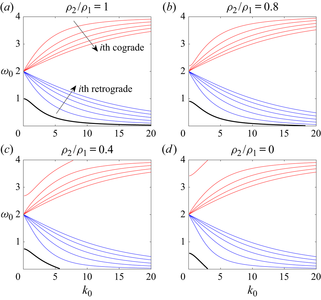
Dispersion curves for the Kelvin wave with  $m=2$ for density ratios from one to zero. Red curves are cograde branches and blue curves are retrograde branches. Only the first five branches of each are plotted. An isolated branch (thick black curve) can be seen below the retrograde branches. Surface tension is zero for all plots.

As discussed in Part 1, density and surface tension act to ‘isolate’ the first cograde mode when  $(\rho _2/\rho _1,S)\ne (1,0)$. In figure 2, the first cograde mode (the uppermost red curve with the largest value of
 $|\omega _0-2|$) departs from the other cograde modes and shifts upward as the density ratio decreases. The isolated branch (thick black line) also shifts downward from its initial position when
 $\rho _2/\rho _1=1$, and the short-wavelength part (large
 $k_0$) of the isolated branch drops below
 $\omega _0=m-2$. On the other hand, when the density ratio increases above one, the situation reverses: the first cograde mode and the isolated mode move closer toward other cograde and retrograde modes. In all cases, Kelvin waves stay neutrally stable. The branch that extends beyond
 $\omega _0 \in [m-2,m+2]$ still has purely real
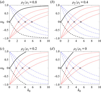
 $\omega _0$. A special scenario is two counter-winding helical waves with azimuthal wavenumber
 $m=-1$ and
 $1$ whose dispersion curves are symmetric about the
 $k_0$-axis (figure 3). In this case, the principal modes are always on the
 $k_0$-axis, and
 $\omega _0=0$.
The first three cograde modes of the Kelvin wave for  $m=-1$ (red) and the first three retrograde modes of the Kelvin wave for
 $m=1$ (blue dashed); their isolated branches (thick solid and dashed) can be seen emanating from
 $(k_0,\omega _0)=(0,0)$. Circles are the first four principal modes with
 $\omega _0=0$. Here
 $S=0$ for all cases.

3.2. Resonance at $O(\delta \gamma )$

The solution of the  $O(\delta \gamma )$ disturbances governed by (2.31)–(2.34) is given in appendix A of Fukumoto (Reference Fukumoto2003). We do not reproduce it here, given its complexity. The solution contains undetermined coefficients
 $\alpha _1$,
 $\beta _1$ (appearing in the linear systems in (C7) and (C8)) which must be non-zero. The boundary conditions in (2.37) and (2.38) are used to obtain the dispersion relation. Note that in order to include surface tension, we need to compute
 $\tilde {f}_1$ from (2.36) before using the dynamic condition for the dispersion relation. In Moore & Saffman (Reference Moore and Saffman1975), Tsai & Widnall (Reference Tsai and Widnall1976) and Fukumoto (Reference Fukumoto2003), computing
 $\tilde {f}_1$ is not necessary because
 $\rho _2/\rho _1=1$ and surface tension is omitted.
Substituting the basic solution (2.14a–c)–(2.16) into the boundary conditions (2.37) and (2.38) gives
 \begin{align} \tilde{u}_1 -\frac{\partial \tilde{\phi}_1}{\partial r} &= \sin2\theta \left[ \frac{\partial \tilde{\phi}_0}{\partial \theta}-\tilde{v}_0+\left(1-\frac{\rho_2}{\rho_1}+3S\right)\tilde{f}_0 \right] \nonumber\\ &\quad +\frac{1}{2}\cos 2\theta \left[-\left(1-\frac{\rho_2}{\rho_1}+3S\right) \frac{\partial \tilde{f}_0}{\partial \theta}+\frac{\partial^2 \tilde{\phi}_0}{\partial r^2} -\frac{\partial \tilde{u}_0}{\partial r}\right]; \end{align}
 \begin{align} &\frac{\rho_2}{\rho_1} \tilde{p}_1 -\mathrm{i}\omega_0\tilde{\phi}_1 +\frac{\partial \tilde{\phi}_1}{\partial \theta} \nonumber\\ &\quad = \mathrm{i} \omega_1\tilde{\phi}_0 +\sin2\theta \frac{\partial \tilde{\phi}_0}{\partial r} +\left(1-\frac{\rho_2}{\rho_1} \right) \tilde{f}_1 -\frac{1}{2}\left({-}1-\frac{\rho_2}{\rho_1}+3S\right)\cos2\theta \frac{\partial \tilde{\phi}_0}{\partial \theta} \nonumber\\ &\qquad +\frac{3}{2}\left( 1-\frac{\rho_2}{\rho_1}+2S \right)\cos2\theta \tilde{f}_0 -\frac{1}{2} \cos2\theta \left[ \frac{\rho_2}{\rho_1}\frac{\partial \tilde{p}_0}{\partial r}-\mathrm{i}\omega_0\frac{\partial \tilde{\phi}_0}{\partial r} +\frac{\partial^2 \tilde{\phi}_0}{\partial r\partial\theta} \right] \nonumber\\ &\qquad -S \left(\frac{\partial^2 \tilde{f}_1}{\partial \theta^2}-k_0^2 \tilde{f}_1 -2k_0 k_1 \tilde{f}_0 -\cos2\theta ~\frac{\partial^2 \tilde{f}_0}{\partial \theta^2}\right). \end{align}
Using the above equations, we obtain two sets of equations for  $m$ and
 $m+2$ in (C1)–(C4). They can be written as two inhomogeneous linear systems (C7) and (C8) for
 $\alpha _1$ and
 $\beta _1$. The dispersion relation (C14) is given by requiring that
 $\alpha _1$ and
 $\beta _1$ do not vanish (see the details in appendix C). A dispersion relation for
 $(k_1,\omega _1)$ determines the stability, and the flow is unstable for
 $\mathrm {Im}\{\omega _1\}>0$. The maximum growth rate
 $\sigma _{1max}$ is given by the maximum imaginary part of
 $\omega _1$ at
 $k_1=0$; and the half-bandwidth of instability,
 $\Delta k_1$, by the range over which the imaginary part of
 $\omega _1$ does not vanish. The expressions for all formulae are too cumbersome to handle manually, and so computer symbolic algebra is utilised to obtain the dispersion relation (C14) and
 $\omega _1$ and
 $\Delta k_1$. A description of procedure is given in detailed in appendix C, and the symbolic algebra files are provided in the supplementary material available at https://doi.org/10.1017/jfm.2020.1157 (as Matlab scripts). We show numerical results for
 $m=-1$ and
 $1$ in the next section, followed by the case for
 $m\geqslant 0$ in § 5.
4. Resonance between waves $m=-1$ and $1$


We first discuss the special case of the resonance pair  $(-1,1)$ in this section. When
 $m=-1$, the resonance is between right- and left-handed helical waves. Fukumoto (Reference Fukumoto2003) gives a detailed discussion of this resonance pair. Widnall et al. (Reference Widnall, Bliss and Tsai1974) and Moore & Saffman (Reference Moore and Saffman1975) imply that the stationary mode is most unstable. The two dispersion curves are mirrored about
 $\omega _0=0$ (see figure 3), and therefore their principal modes are exactly on the
 $k_0$-axis.
4.1. Principal modes ($\omega _0=0$)

We substitute  $m=-1$ and
 $\omega _0=0$ for the principal modes of stationary waves (circles in figure 3). The maximum growth rate
 $\sigma _{1max}$ and half the instability bandwidth
 $\Delta k_1$ are then calculated using computer symbolic algebra. To verify the result of the symbolic calculation, results for
 $(\rho _2/\rho _1,S)=(1,0)$ are compared with those in Fukumoto (Reference Fukumoto2003) in table 1. The present study has
 $\sigma _{1max}$ accurate to 10 significant figures and
 $\Delta k_1$ up to five significant figures. As seen in figure 3, the first principal mode at
 $(k_0,\omega _0)=(0,0)$ is independent of
 $\rho _2/\rho _1$ and
 $S$, so we do not include it in the comparison here.
For the  $m=-1$ and
 $1$ resonances, present results for
 $\rho _2/\rho _1=1$ compared with table 1 of Fukumoto (Reference Fukumoto2003). Each row represents a principal mode with
 $k_0=0$.

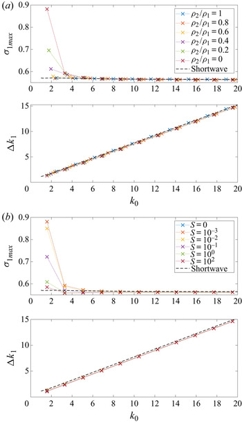
The principal modes’ maximum growth rates and instability half-bandwidths are plotted as functions of  $\rho _2/\rho _1$ in figure 4(a) for
 $S=0$. The second principal mode (blue curve) is the most unstable mode. The largest growth rate is at
 $\rho _2/\rho _1=0$ with a value of
 $\sigma _{1max}= 0.882$. The least unstable density ratio is
 $0.915$, where the second and third principal modes have a growth rate of
 $0.5696$. The instability half-bandwidth,
 $\Delta k_1$, is strongly correlated with the axial wavenumber
 $k_0$, and the principal mode with higher
 $k_0$ has wider instability bandwidth. Figure 4(b) shows the effect of surface tension when
 $\rho _2/\rho _1=0.001$. The density ratio
 $0.001$ is picked because it is close to the typical ratio between air and water. Surface tension merely changes the locations of principal modes. The second principal mode dominates the instability. The growth rate is
 $0.8803$ at
 $S=10^{-4}$ and drops to
 $0.585$ when
 $S=500$.
Principal modes  $(k_0, 0)$ for
 $(m,m+2) = (-1,1)$, the maximum growth rate
 $\sigma _{1max}$ and the instability half-bandwidth
 $\Delta k_1$ plotted versus: (a) density ratio
 $\rho _2/\rho _1 \in [0.005,100]$ for
 $S=0$; (b) surface tension
 $S \in [0,500]$ with
 $\rho _2/\rho _1=0.001$. The second to sixth principal modes are the blue, red, amber, purple and green curves.

The growth rate and the instability half-bandwidth are calculated for large  $k_0$ in figure 5 with different values of
 $\rho _2/\rho _1\in [0,1]$ and
 $S\in [0,100]$. Density only has an effect on the growth rate
 $\sigma _{1max}$ for principal modes with
 $k_0<10$. The growth rates for different values of
 $\rho _2/\rho _1$ and
 $S$ all converge to a fixed value
 $0.5625$ as
 $k_0\to \infty$. The short-wavelength limit given in (5.13), (5.14) of Fukumoto (Reference Fukumoto2003) for
 $(\rho _2/\rho _1,S)=(1,0)$ as
 \begin{gather} \sigma_{1max} \approx \frac{9}{16} \left( 1+\frac{1}{12k_0}-\frac{7}{48k_0^2}+\frac{5}{64k_0^3} \right), \end{gather}
 \begin{gather}\Delta k_1 \approx \frac{3 k_0}{4} \left( 1+\frac{1}{3k_0}+\frac{5}{24k_0^3} \right), \end{gather}
is plotted as dashed lines in figure 5.
Maximum growth rate  $\sigma _{1max}$ and unstable half-bandwidth
 $\Delta k_1$ of principal modes with axial wavenumber
 $k_0<20$ for helical waves
 $(m,m+2)=(-1,1)$: (a) different
 $\rho _2/\rho _1$ with
 $S=0$; (b) different
 $S$ with
 $\rho _2/\rho _1=0.001$. The dashed line is the short-wavelength asymptotic result (4.1) for
 $\rho _2/\rho _1=1$ and
 $S=0$.

4.2. Non-principal modes
For stationary waves  $m=\pm 1$, non-principal modes are intersection points where
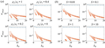
 $\omega _0\ne 0$. Theoretically, an infinite number of non-principal modes exist because the two Kelvin waves have an infinite number of intersection points. Here we show only those non-principal modes for
 $k_0\in [0,20]$ and
 $\omega _0 \in (0,0.5]$ in figure 6. In the case
 $\rho _2/\rho _1=1$ and
 $S=0$, the growth rates of non-principal modes are at least two orders of magnitude smaller than that of the principal modes (see figure 6a). As the density ratio decreases to zero, the maximum growth rates of non-principal modes grow and become one order of magnitude smaller than those of the principal modes. The trend reverses for increasing surface tension. The maximum growth rate of non-principal modes is one order of magnitude less than that of the principal modes and that difference widens to more than two orders of magnitude for
 $S=10$ in figure 6(b). With variations in either density or surface tension, the instability of the principal modes always dominates over non-principal modes.
Maximum growth rate  $\sigma _{1max}$ for the modes of the
 $(-1,1)$ resonance with variations of (a)
 $\rho _2/\rho _1$ for
 $S=0$ and (b)
 $S$ for
 $\rho _2/\rho _1=0.001$. Principal modes (with
 $k_0\leqslant 20$) are marked by blue crosses whereas other modes are red circles. The black dashed line is the short-wavelength asymptotic result (4.1) for
 $\rho _2/\rho _1=1$ and
 $S=0$.

5. Resonance between waves $m$ and $m+2$ ($m\geqslant 0$)


We continue to explore resonant pairs of  $(m,m+2)$ other than
 $(-1,1)$. Among those pairs, the case of
 $(0,2)$ is particular interesting. As Fukumoto (Reference Fukumoto2003) states, this is a result of its resistance to viscous dissipation when the Reynolds number is not sufficiently large (Éloy & Le Dizès Reference Éloy and Le Dizès2001). We first discuss the
 $(0,2)$ resonant pair, followed by other helical waves.
5.1. The case $m=0$

We calculate the growth rate  $\sigma _{1max}$ and half the unstable bandwidth
 $\Delta k_1$ for the first five principal modes. The definition of principal modes is the same as in Éloy & Le Dizès (Reference Éloy and Le Dizès2001) and Fukumoto (Reference Fukumoto2003): the first principal mode is the intersection between the first cograde mode for
 $m=0$ and the isolated mode for
 $m=2$, the second principal mode is the second cograde mode for
 $m=0$ intersected by the first retrograde mode for
 $m=2$, and so on. The location
 $(k_0,\omega _0)$ of the principal modes in figure 7(a) shows that
 $k_0$ shifts to lower wavelengths as the density ratio
 $\rho _2/\rho _1$ drops below one. The growth rate of the first principal mode has a cusp at
 $\rho _2/\rho _1 = 0.215$ with
 $\sigma _{1max} \approx 4.32$. The mode is then stable below
 $\rho _2/\rho _1 < 0.215$, and this mode does not exist for
 $\rho _2/\rho _1 \lesssim 0.09$ because the two branches on which the first principal mode is located do not cross each other when the density ratio drops below
 $0.09$ (as explained in § 3.1). The third principal mode is the most unstable with
 $\sigma _{1max}=0.5668647793$ for
 $\rho _2/\rho _1 =1$ in the calculation of Fukumoto (Reference Fukumoto2003). In our calculation with density variations, the second principal mode is the most unstable mode as
 $\rho _2/\rho _1 \to 0$ with
 $\sigma _{1max} = 0.6028$, whereas the first principal mode is the most unstable for
 $\rho _2/\rho _1 \to 100$ with
 $\sigma _{1max}=0.6167$. The trend in
 $\Delta k_1$ is very similar to that in
 $k_0$: as the density ratio decreases the unstable bandwidth decreases. We also extend our calculation to other principal modes with higher axial wavenumber
 $k_0$ in figure 9. The growth rate is asymptotically close to that of (4.1) in the short-wavelength regime for
 $\rho _2/\rho _1 =1$. For large
 $k_0$,
 $\Delta k_1$ increases linearly with
 $k_0$ and the slopes are identical except for
 $k_0<4$.
Principal modes for  $(m,m+2) = (0,2)$, maximum growth rate
 $\sigma _{1max}$ and the instability half-bandwidth
 $\Delta k_1$ plotted versus: (a) density ratio
 $\rho _2/\rho _1 \in [0.005,100]$ for
 $S=0$; (b) surface tension
 $S \in [0,500]$ at
 $\rho _2/\rho _1=0.2$. The first to fifth principal modes are the blue, red, amber, purple and green curves.

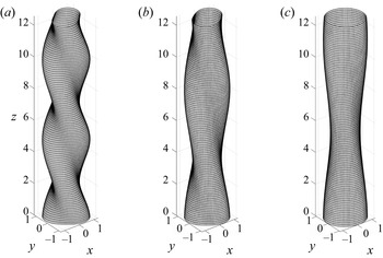
The disturbed boundary of the first principal mode in the  $(0,2)$ resonance is shown in figure 8. The shape of the resonant disturbance transitions from helical waves to bulging waves as density ratio decreases. The axial wavelength of the disturbance increases (
 $k_0$ decreases) as the density ratio decreases. This is due to the effect of density on the Kelvin wave dispersion relation. Consequently the location of the intersection point changes. Given that the strain field is applied uniformly along the
 $z$-direction, bulging modes (figure 8c) are more susceptible to the strain field. Because a bulging mode is axisymmetric with respect to the
 $z$-axis, it has no preferred direction and can deform more easily. For helical modes, the twist makes the core structure vary constantly per unit length in
 $z$, so that the core is more resistant to a strain of uniform direction.
Disturbed boundary for the first principal mode of the  $(0,2)$ resonance with different density ratio: (a)
 $\rho _2/\rho _1=1$,
 $(k_0,\omega _0)=(1.242233570,0.8326707800)$; (b)
 $\rho _2/\rho _1=0.4$,
 $(k_0,\omega _0)=(0.7529505549,0.6784320753)$; (c)
 $\rho _2/\rho _1=0.22$,
 $(k_0,\omega _0)=(0.5503572727,0.6335367950)$. The disturbance transitions from helical mode into bulging mode as
 $\rho _2/\rho _1$ decreases.

Maximum growth rate  $\sigma _{1max}$ and unstable half-bandwidth
 $\Delta k_1$ of principal modes with axial wavenumber
 $k_0<20$ for
 $(m,m+2)=(0,2)$ with different
 $\rho _2/\rho _1$ with
 $S=0$. The dashed line is the short-wavelength asymptotic result (4.1) for
 $\rho _2/\rho _1=1$.

The dependence on surface tension  $S$ is shown in figure 7(b) for
 $\rho _2/\rho _1=0.2$. The first principal mode does not exist as surface tension increases to a value above
 $S \approx 0.14$ and is always unstable below that threshold. The effect on the other four principal modes is not significant. The second principal mode (red curve) has the biggest drop in
 $\sigma _{1max}$ from a value of
 $0.6049$ to
 $0.5482$ at
 $S=100$. The mitigation of the instability by surface tension is as expected, since surface tension makes the interface more resistant to deformation when subjected to a strain.
5.2. Other pairs $(m,m+2)$

Moving on to higher resonance pairs, e.g.  $(m,m+2)=(4,6)$, we found the change in the positions
 $(k_0,\omega _0)$ of principal modes (see figure 10a) to be qualitatively similar to that for the
 $(0,2)$ pair. The first principal mode (in blue in figure 10) disappears near a larger density ratio at the value of
 $\rho _2/\rho _1=0.72$. The most significant difference is how the growth rate behaves before the first principal mode disappears. For
 $(m,m+2)=(0,2)$, the growth rate of the first principal mode increases drastically and then drops to zero before the first principal mode vanishes (figure 7a), whereas for
 $(m,m+2)=(4,6)$,
 $\sigma _{1max}$ plunges to zero in figure 10(a) and never exceeds
 $0.6$. The dependence on surface tension
 $S$ is shown in figure 10(b). The growth rate
 $\sigma _{1max}$ decreases only slightly, and is almost independent of surface tension for
 $S \gtrsim 1$.
Principal modes for  $(m,m+2) = (4,6)$, the maximum growth rate
 $\sigma _{1max}$ and the instability half-bandwidth
 $\Delta k_1$ are plotted versus: (a) density ratio
 $\rho _2/\rho _1 \in [0.01,100]$ for
 $S=0$; (b) surface tension
 $S \in [0,100]$ at
 $\rho _2/\rho _1=0.2$. The first to fifth principal modes are the blue, red, amber, purple and green curves.

Resonance pairs with higher azimuthal wavenumber  $m$ have smaller growth rate
 $\sigma _{1max}$ for the MSTW instability, whereas the curvature instability is more unstable for larger
 $m$ (see Chang & Llewellyn Smith Reference Chang and Llewellyn Smith2021). In figure 11 we plot the maximum growth rate among intersection points (resonant modes) that include the principal modes and a few non-principal modes for axial wavenumber
 $k_0 \leqslant 20$, as a function of density ratio
 $\rho _2/\rho _1$. The maximum growth rate decreases as
 $m$ increases. This is due to the strain field, which kills the small-scale disturbances on the boundary. For a fixed value of
 $m$, the growth rate is constant for very large and small
 $\rho _2/\rho _1$, and the curve has a dip in the middle at
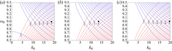
 $\rho _2/\rho _1=0.925$. That is where the most unstable mode (that with the largest growth rate) jumps from one intersection point of Kelvin waves to another. As shown in figure 12, the most unstable mode, represented by a black dot, switches from the seventh principal mode to the fourth principal mode as the density ratio increases from
 $0.925$ to
 $1.069$.
Maximum growth rate for modes with  $\rho _2/\rho _1 \in [0.01,100]$ and
 $S=0$. Blue, red, amber and purple curves are for resonance pairs
 $(m,m+2)$,
 $m=2$,
 $4$,
 $8$ and
 $16$, respectively. The vertical dashed line is the value
 $\rho _2/\rho _1=0.925$ where the growth rate has a dip.

Intersection points of the pair  $(m,m+2) =(8,10)$: (a)
 $\rho _2/\rho _1=0.925$; (b)
 $\rho _2/\rho _1=1.069$; and (c)
 $\rho _2/\rho _1=10$. Surface tension is zero. Principal modes are labelled by numbered circles; the black dot is the mode with largest growth rate. The most unstable mode switches from the seventh principal mode to the fourth principal mode, then back to the seventh, causing the discontinuity in
 $\sigma _{1max}$.

Given that the whole calculation is based on discrete intersection points of Kelvin waves, the largest growth rate among all modes can have a discontinuity while it switches from one intersection point to another. That happens when the previous most unstable mode had decayed or disappeared, and another mode takes over. The instability of a resonant mode is a function of its location  $(k_0,\omega _0)$ and the location is a function of density ratio and surface tension. The migrations of the first cograde mode and the isolated mode discussed in § 3 also have a huge influence on the location of intersection points.
6. Conclusion
The parametric instability of a vortex column subjected to a weak strain field has been investigated for varying density ratio and surface tension. The instability, the MSTW instability, is the result of the resonance between two Kelvin waves of azimuthal wavenumber  $m$ and
 $m+2$. The resonance is fed by a quadrupole field which comes from the correction to the basic state at
 $O(\gamma )$. We have extended the calculation by Fukumoto (Reference Fukumoto2003) to a parameter space
 $(\rho _2/\rho _1, S)$, where
 $(\rho _2/\rho _1, S)=(1,0)$ is the previous result.
Two distinguished types of resonances are examined. The first corresponds to stationary helical waves with azimuthal wavenumber  $m=\pm 1$. The strained vortex is most unstable when the density ratio is very small (
 $\rho _2/\rho _1\to 0$): the maximum growth rate is
 $\sigma _{1max}\approx 0.88$ compared with a minimum of
 $0.57$ near
 $\rho _2/\rho _1=1$. Surface tension mitigates the instability of the vortex for
 $S>0.01$, and the maximum growth rate drops from
 $0.88$ to
 $0.58$ as
 $S\to \infty$. We have also shown that the most unstable modes are dominated by the principal modes in the resonances for
 $m=\pm 1$ stationary waves. The second type of resonances is for azimuthal wavenumber
 $m \geqslant 0$, and
 $m=0$ is a particular case of bulging modes. For the
 $(0,2)$ resonance, the maximum growth rate from the first principal mode is maximised near
 $\rho _2/\rho _1=0.215$ with a very large value, and that mode vanishes as
 $\rho _2/\rho _1 \to 0$ whereas the second principal mode takes over to become most unstable. We have also shown that the maximum growth rate decreases as the azimuthal wavenumber
 $m$ increases, which is in contrast to the curvature instability.
In the recent study by Hattori et al. (Reference Hattori, Blanco-Rodriguez and Le Dizès2019) using DNS, the short-wavelength MSTW instability (the elliptic instability) was shown to be more unstable than the curvature instability for a vortex ring of Gaussian core structure. This result demonstrates the validity of the theoretical prediction in Blanco-Rodriguez & Le Dizès (Reference Blanco-Rodriguez and Le Dizès2016) of the elliptic instability for the Batchelor vortex (a vortex with a Gaussian core). Furthermore, the analytical result of curvature instability for a Gaussian core (Blanco-Rodriguez & Le Dizès Reference Blanco-Rodriguez and Le Dizès2017) has also been confirmed in Hattori et al. (Reference Hattori, Blanco-Rodriguez and Le Dizès2019). This is the first numerical evidence for the curvature instability after its discovery by Hattori & Fukumoto (Reference Hattori and Fukumoto2003) and Fukumoto & Hattori (Reference Fukumoto and Hattori2005) for vortex rings. The present study considers uniform cores with a jump in density across the boundary. It would be of interest to extend this result to continuous vorticity and density distributions. It will be more complicated to carry out a full numerical simulation for this kind of problem with large density jumps at the boundary of the vortices. Direct numerical simulations to detect the curvature and MSTW instabilities of vortices with density differences hence remain tasks for future investigation.
Supplementary material
Supplementary material is available at https://doi.org/10.1017/jfm.2020.1157.
Acknowledgement
Conversations with L. Lacaze were helpful.
Funding
This work was supported by the National Science Foundation under award number CBET-1706934.
Declaration of interests
The authors report no conflict of interest.
Appendix A. The mean-flow solution
The basic solution is written as a perturbation series in  $\gamma$ in (2.11a–c). The leading-order solution is the Rankine vortex with a circular boundary. The pressure comes from solving
 \begin{equation} {-}\frac{V_0^2}{r} ={-}\frac{\partial P_0}{\partial r} \end{equation}
inside the vortex and the Bernoulli equation outside. The pressure at  $r=1$ is matched using
 \begin{equation} \frac{\rho_2}{\rho_1}P_0 +\frac{1}{2} \left(\frac{\partial \varPhi_0}{\partial \theta}\right)^2= S. \end{equation}
At  $O(\gamma )$, (2.12a,b)–(2.15) give
 \begin{gather} \frac{\partial U_1}{\partial \theta} -2 V_1 ={-}\frac{\partial P_1}{\partial r}, \end{gather}
 \begin{gather}2U_1 +\frac{\partial V_1}{\partial \theta} ={-}\frac{1}{r}\frac{\partial P_1}{\partial \theta}, \end{gather}
 \begin{gather}\frac{\partial U_1}{\partial r} +\frac{U_1}{r} +\frac{1}{r}\frac{\partial V_1}{\partial \theta} = 0 \end{gather}
for  $r<1+\gamma F_1$ and
 \begin{equation} \frac{\partial^2 \varPhi_1}{\partial r^2} +\frac{1}{r}\frac{\partial \varPhi_1}{\partial r} +\frac{1}{r^2}\frac{\partial^2 \varPhi_1}{\partial \theta^2} = 0 \end{equation}
for  $r>1+\gamma F_1$. The matching condition from (2.9) and (2.10), linearised on
 $r=1$, is
 \begin{gather} U_1 -\frac{\mathrm{d} F_1}{\mathrm{d} \theta} = 0, \end{gather}
 \begin{gather}\frac{\partial \varPhi_1}{\partial r} -\frac{\mathrm{d} F_1}{\mathrm{d} \theta} = 0, \end{gather}
 \begin{gather}\frac{\rho_2}{\rho_1}P_1 +\frac{\partial \varPhi_1}{\partial \theta} +F_1 \left(\frac{\rho_2}{\rho_1} -1\right) ={-}S \left( F_1 +\frac{\partial^2 F_1}{\partial \theta^2} \right). \end{gather}
Appendix B. The solution for Kelvin waves
Kelvin waves satisfying (2.23)–(2.27) with azimuthal wavenumber  $m$ are given by
 \begin{equation} \left.\begin{gathered} p_0^{(m)} = \textrm{J}_m(\eta_1r) \beta_0^{(m)}, \\ u_0^{(m)} = \frac{\mathrm{i}}{\omega_0-m+2} \left[ -\frac{m}{r}\textrm{J}_m(\eta_1r) +\frac{\omega_0-m}{\omega_0-m-2}\eta_1 \textrm{J}_{m+1}(\eta_1r) \right]\beta_0^{(m)}, \\ v_0^{(m)} = \frac{1}{\omega_0-m+2} \left[ \frac{m}{r}\textrm{J}_m(\eta_1r) +\frac{2}{\omega_0-m-2} \eta_1 \textrm{J}_{m+1}(\eta_1r) \right] \beta_0^{(m)}, \\ w_0^{(m)} = \frac{k_0}{\omega_0-m}\textrm{J}_m(\eta_1r) \beta_0^{(m)} \end{gathered}\right\}\end{equation}
for  $r<1+\tilde {f}_0$. The radial wavenumber is
 \begin{equation} \eta_1^2 = \left[\frac{4}{(\omega_0-m)^2}-1\right] k_0^2. \end{equation}
The boundary disturbance is given by
 \begin{equation} f_0^{(m)} = \frac{-1}{\mathrm{i} (\omega_0-m)} u_0^{(m)}, \end{equation}
using the kinematic boundary condition. For  $r>1+\tilde {f}_0$,
 \begin{equation} \phi_0^{(m)} = \textrm{K}_m(k_0r) \alpha_0^{(m)}. \end{equation}
The  $(m+2)$ waves are obtained by replacing
 $m$ in the formulae by
 $m+2$. Appropriate recurrence relations are then used to reduce the order of the Bessel functions.
Appendix C. Solvability conditions and dispersion relation for $(k_1,\omega _1)$

Writing the boundary conditions (2.37) and (2.38) for the  $O(\delta \gamma )$ solutions gives
 \begin{align} u_1^{(m)} - \frac{\mathrm{d} \phi_1}{\mathrm{d} r}^{(m)} &={-}\frac{m+2}{2}\phi_0^{(m+2)} -\frac{\mathrm{i}}{2}v_0^{(m+2)} +\frac{1}{4}\left[\frac{\mathrm{d}^2 \phi_0}{\mathrm{d} r^2}^{(m+2)} - \frac{\mathrm{d} u_0}{\mathrm{d} r}^{(m+2)} \right] \nonumber\\ &\quad +\frac{\mathrm{i}}{2}\left(1-\frac{\rho_2}{\rho_1}+3S\right)f_0^{(m+2)} -\frac{\mathrm{i}(m+2)}{4}\left(1-\frac{\rho_2}{\rho_1}+3S\right)f_0^{(m+2)}, \end{align}
 \begin{align} &\frac{\rho_2}{\rho_1}p_1^{(m)} -\mathrm{i}(\omega_0-m)\phi_1^{(m)} \nonumber\\ &\quad = \mathrm{i} \omega_1 \phi_0^{(m)} -\frac{1}{4} \left[\frac{\rho_2}{\rho_1}\frac{\mathrm{d} p_0}{\mathrm{d} r}^{(m+2)}-\mathrm{i}(\omega_0-m)\frac{\mathrm{d} \phi_0}{\mathrm{d} r}^{(m+2)} \right] \nonumber\\ &\qquad -\frac{\mathrm{i}(m+2)}{4}\left({-}1-\frac{\rho_2}{\rho_1}+3S\right)\phi_0^{(m+2)} +\frac{3}{4}\left(1-\frac{\rho_2}{\rho_1}+2S\right)f_0^{(m+2)} \nonumber\\ &\qquad +S\left[2k_0k_1f_0^{(m)} -\frac{(m+2)^2}{2}f_0^{(m+2)} \right] \nonumber\\ &\qquad +\left[ 1-\frac{\rho_2}{\rho_1}+ S(m^2+k_0^2) \right] f_1^{(m)} \end{align}
for wave  $m$, and
 \begin{align} u_1^{(m+2)} - \frac{\mathrm{d} \phi_1}{\mathrm{d} r}^{(m+2)} &= \frac{m}{2}\phi_0^{(m)} +\frac{\mathrm{i}}{2}v_0^{(m)} +\frac{1}{4}\left[\frac{\mathrm{d}^2 \phi_0}{\mathrm{d} r^2}^{(m)} -\frac{\mathrm{d} u_0}{\mathrm{d} r}^{(m)} \right] \nonumber\\ & \quad -\frac{\mathrm{i}}{2}\left(1-\frac{\rho_2}{\rho_1}+3S\right)f_0^{(m)} -\frac{\mathrm{i} m}{4}\left(1-\frac{\rho_2}{\rho_1}+3S\right)f_0^{(m)}, \end{align}
 \begin{align} & \frac{\rho_2}{\rho_1}p_1^{(m+2)} -\mathrm{i}(\omega_0-m-2)\phi_1^{(m+2)} \nonumber\\ &\quad = \mathrm{i} \omega_1 \phi_0^{(m+2)} -\frac{1}{4} \left[\frac{\rho_2}{\rho_1}\frac{\mathrm{d} p_0}{\mathrm{d} r}^{(m)}-\mathrm{i}(\omega_0-m-2)\frac{\mathrm{d} \phi_0}{\mathrm{d} r}^{(m)} \right] \nonumber\\ & \qquad -\frac{\mathrm{i} m}{4}\left({-}1-\frac{\rho_2}{\rho_1}+3S\right)\phi_0^{(m)} +\frac{3}{4}\left(1-\frac{\rho_2}{\rho_1}+2S\right)f_0^{(m)} \nonumber\\ &\qquad +S\left[2k_0k_1f_0^{(m+2)} -\frac{m^2}{2}f_0^{(m)} \right] \nonumber\\ &\qquad +\left\{1-\frac{\rho_2}{\rho_1}+ S[(m+2)^2+k_0^2]\right\} f_1^{(m+2)} \end{align}
for wave  $m+2$ (cf. (4.8) and (4.9) in Fukumoto (Reference Fukumoto2003), for
 $\rho _2/\rho _1=1$,
 $S=0$). Unlike the case of Tsai & Widnall (Reference Tsai and Widnall1976) and Fukumoto (Reference Fukumoto2003),
 $f_1$ needs to be obtained from the above equations in order to calculate the dispersion relation. We have
 \begin{gather} f_1^{(m)} = \frac{-1}{\mathrm{i} (\omega_0-m)} \left[ u_1^{(m)} +\mathrm{i} \omega_1 f_0^{(m)} + \frac{\mathrm{i}}{2}v_0^{(m+2)} +\frac{\mathrm{i}(m+1)}{2}f_0^{(m+2)} +\frac{1}{4}\frac{\mathrm{d} u_0}{\mathrm{d} r}^{(m+2)} \right], \end{gather}
 \begin{gather}f_1^{(m+2)} = \frac{-1}{\mathrm{i} (\omega_0-m-2)} \left[ u_1^{(m+2)} +\mathrm{i} \omega_1 f_0^{(m+2)} - \frac{\mathrm{i}}{2}v_0^{(m)} +\frac{\mathrm{i}(m+1)}{2}f_0^{(m)} +\frac{1}{4}\frac{\mathrm{d} u_0}{\mathrm{d} r}^{(m)} \right]. \end{gather}
The dispersion relation relating  $k_1$ and
 $\omega _1$ for disturbances at
 $O(\delta \gamma )$ is determined as follows. The
 $O(\delta \gamma )$ disturbance satisfies (2.31)–(2.35) with undetermined coefficients (wave amplitudes)
 $\alpha _1$,
 $\beta _1$ in the solution, which need to be determined using the boundary conditions at
 $O(\delta \gamma )$. The boundary conditions (C1) and (C2) for mode
 $m$ lead to an inhomogeneous linear system of the form
 \begin{equation} \left[ \begin{array}{@{}cc@{}} \boldsymbol{\mathsf{M}}_{11} & \boldsymbol{\mathsf{M}}_{12} \\ \boldsymbol{\mathsf{M}}_{21} & \boldsymbol{\mathsf{M}}_{22} \end{array} \right] \left[ \begin{array}{@{}c@{}} \alpha_1^{(m)} \\ \beta_1^{(m)} \end{array} \right] = \left[ \begin{array}{@{}c@{}} F_1 \\ F_2 \end{array} \right], \end{equation}
whereas (C3) and (C4) for mode  $m+2$ become
 \begin{equation} \left[ \begin{array}{@{}cc@{}} \boldsymbol{\mathsf{N}}_{11} & \boldsymbol{\mathsf{N}}_{12} \\ \boldsymbol{\mathsf{N}}_{21} & \boldsymbol{\mathsf{N}}_{22} \end{array} \right] \left[ \begin{array}{@{}c@{}} \alpha_1^{(m+2)} \\ \beta_1^{(m+2)} \end{array} \right] = \left[ \begin{array}{@{}c@{}} G_1 \\ G_2 \end{array} \right]. \end{equation}
The vectors  $\boldsymbol {F}$ and
 $\boldsymbol {G}$ consist of the
 $O(\delta )$ solution which has undetermined coefficients
 $\alpha _0$ and
 $\beta _0$. They also depend on known quantities,
 $m$,
 $k_0$,
 $\omega _0$,
 $\rho _2/\rho _1$,
 $S$, and on the unknowns
 $k_1$ and
 $\omega _1$.
The matrices  ${\boldsymbol{\mathsf{M}}}$ and
 ${\boldsymbol{\mathsf{N}}}$ on the left-hand side of (C7) and (C8) depend on
 $m$,
 $\omega _0$,
 $k_0$,
 $\rho _2/\rho _1$,
 $S$. (
 ${\boldsymbol{\mathsf{M}}}$,
 ${\boldsymbol{\mathsf{N}}}$ and
 $\boldsymbol {F}$,
 $\boldsymbol {G}$ can be found in the Matlab supplementary material. We do not give them here because of their length.) The two linear systems are singular, i.e. their determinants are zero. The solvability condition requires that the vectors
 $\boldsymbol {F}$ and
 $\boldsymbol {G}$ lie in the image space of
 ${\boldsymbol{\mathsf{M}}}$ and
 ${\boldsymbol{\mathsf{N}}}$, i.e.
 \begin{equation} \left.\begin{gathered} \boldsymbol{\mathsf{M}}_{11} F_2 -\boldsymbol{\mathsf{M}}_{21} F_1 = 0, \\ \boldsymbol{\mathsf{N}}_{11} G_2 -\boldsymbol{\mathsf{N}}_{21} G_1 = 0. \end{gathered}\right\} \end{equation}
Using the relations
 \begin{align} \alpha_0^{(m)} ={-} \frac{\mathrm{i} \textrm{J}_m(\eta_1)}{(\omega_0-m)\textrm{K}_m(k_0)} \beta_0^{(m)}, \quad \alpha_0^{(m+2)} ={-} \frac{\mathrm{i} \textrm{J}_{m+2}(\eta_2)}{(\omega_0-m-2)\textrm{K}_{m+2}(k_0)} \beta_0^{(m+2)}, \end{align}
we substitute  $\alpha _0^{(m)}$ and
 $\alpha _0^{(m+2)}$ into (C9) and convert it into a homogeneous linear system
 \begin{equation} \left[ \begin{array}{@{}cc@{}} \boldsymbol{\mathsf{D}}_{11} & \boldsymbol{\mathsf{D}}_{12} \\ \boldsymbol{\mathsf{D}}_{21} & \boldsymbol{\mathsf{D}}_{22} \end{array} \right] \left[ \begin{array}{@{}l@{}} \beta_0^{(m)} \\ \beta_0^{(m+2)} \end{array} \right] = \boldsymbol{0}. \end{equation}
For non-trivial  $\beta _0^{(m)}$ and
 $\beta _0^{(m+2)}$, the resulting determinant equation
 \begin{equation} \boldsymbol{\mathsf{D}}_{11}\boldsymbol{\mathsf{D}}_{22}-\boldsymbol{\mathsf{D}}_{12}\boldsymbol{\mathsf{D}}_{21} = 0 \end{equation}
leads to the dispersion relation for  $(k_1, \omega _1)$. This is a quadratic equation for
 $\omega _1$, where
 $\omega _1$ is obtained from
 $\boldsymbol{\mathsf{D}}_{11}$ and
 $\boldsymbol{\mathsf{D}}_{22}$ via
 \begin{equation} \boldsymbol{\mathsf{D}}_{11} = \mu_1 \omega_1 +\mu_2, \quad \boldsymbol{\mathsf{D}}_{22} = \mu_3 \omega_1 +\mu_4. \end{equation}
The dispersion relation is hence
 \begin{equation} \mu_1 \mu_3 \omega_1^2 +(\mu_1 \mu_4+\mu_2\mu_3) \omega_1+\mu_2\mu_4-\boldsymbol{\mathsf{D}}_{12}\boldsymbol{\mathsf{D}}_{21} = 0. \end{equation}
Expressions for  $\mu _i$ and
 $D_{12}$,
 $D_{21}$ are given in the supplementary material (Matlab scripts).
These quantities are functions of  $k_1$ with
 $m$,
 $\omega _0$,
 $k_0$,
 $\rho _2/\rho _1$ and
 $S$ all given. The growth rate
 $\sigma _1 = |\textrm {Im}{(\omega _1)}|$ has a maximum when
 $k_1=0$ where
 $\mu _2=\mu _4=0$, giving
 \begin{equation} \sigma_{1max} = \sqrt{-\frac{\boldsymbol{\mathsf{D}}_{12}\boldsymbol{\mathsf{D}}_{21}}{\mu_1 \mu_3}}. \end{equation}
One half of the unstable bandwidth  $\Delta k_1$ is calculated by finding the root
 $k_1$ of
 \begin{equation} (\mu_1 \mu_4+\mu_2\mu_3)^2 -4\mu_1 \mu_3 (\mu_2\mu_4-\boldsymbol{\mathsf{D}}_{12}\boldsymbol{\mathsf{D}}_{21} )=0, \end{equation}
and  $\Delta k_1$ is calculated by solving a quadratic equation for the maximum root of
 $k_1$ in (C16).